4
WARNING – ELECTROCUTION HAZARD.
High voltage electricity is present in the pool and
spa equipment.Highvoltageelectricitycancauseshockandelectrocution.Shockandelectrocutioncan
result in severe personal injury or death.
•
All electrical wiring MUST be in conformance with applicable local codes, regulations and the
National Electrical Code (NEC).
•
Beforeperforminganyserviceormaintenanceonelectricalequipmentturnoffallelectricalpower.
•
Contact a licensed electrician or building inspector for information on local electrical codes for
bondingrequirements.
• Verifywaterdischargefromtheltermanualairreliefvalveisdirectedawayfromelectricaldevices.
• Donotlocatepumpcontrolsoverornearlter.
WARNING – SUCTION ENTRAPMENT HAZARD.
Suction in suction outlets and/or suction outlet covers that are, damaged, broken, cracked, missing, or
unsecured can cause severe injury and/or death due to the following entrapment hazards:
Hair Entrapment – Hair can become entangled in suction outlet cover.
Limb Entrapment – A limb inserted into an opening of a suction outlet sump or suction outlet cover that is
damaged, broken, cracked, missing, or not securely attached can result in a mechanical bind or swelling of
the limb.
Body Suction Entrapment – A negative pressure applied to a large portion of the body or limbs can result in
an entrapment.
Evisceration/ Disembowelment Entrapment – A negative pressure applied directly to the intestines through
an unprotected suction outlet sump or suction outlet cover that is, damaged, broken, cracked, missing, or
unsecured can result in evisceration/ disembowelment entrapment.
Mechanical Entrapment – There is potential for jewelry, swimsuit, hair decorations, nger, toe or knuckle to
be caught in an opening of a suction outlet cover resulting in mechanical entrapment.
WARNING – To Reduce the Risk of Entrapment Hazards:
• Aminimumoftwofunctioningsuctionoutletsperpumpmustbeinstalled.Suctionoutletsinthesameplane
(i.e. oor or wall), must be installed a minimum of three feet (3’)
[1 meter] apart, as measured from near point to near point.
• Dualsuctionoutletsshallbeplacedinsuchlocationsanddistancestoavoid“dualblockage”byauser.
• Dualsuctionoutletsshallnotbelocatedonseatingareasoronthebackrestforsuchseatingareas.
• ThepoolorspacirculationsystemshallbedesignedtocomplywithANSI/APSP-72006.
• SuctionoutletcoversshallconformtoANSI/ASMEA112.19.8
• NeverusePoolorSpaifanysuctionoutletcomponent(cover/grate)isdamaged,broken,cracked,missing,
or not securely attached.
• Immediatelyreplacedamaged,broken,cracked,missing,ornotsecurelyattachedsuctionoutletcomponents.
• TheCPSPaswellastheICCInternationalResidentialCodePartIX,AppendixG,SectionAG106species
the installation of a safety vacuum release system conforming to ASME A112.19.17, or an approved gravity
drain system.
• Failuretoremovepressuretestplugsand/orplugsusedinwinterizationofthepool/spafromthesuctionoutlets
can result in an increased potential for suction entrapment.
• Failuretokeepsuctionoutletcomponentsclearofdebris,suchasleaves,dirt,hair,paperandothermaterial
can result in an increased potential for suction entrapment.
Suctionoutletcoversandgrateshaveanitelife.Theyshouldbeinspectedfrequentlyandreplacedwithin
specied life.
5
2. General Information
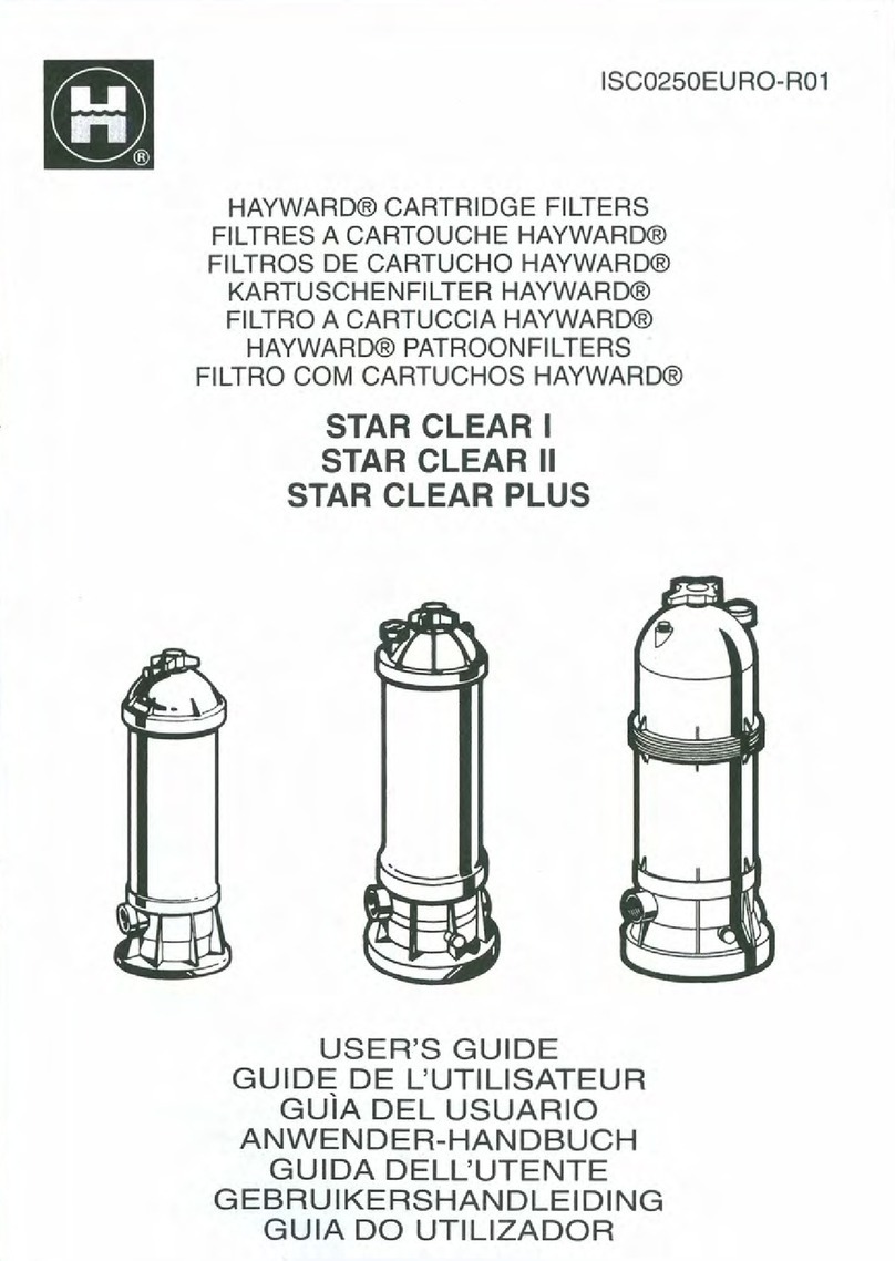
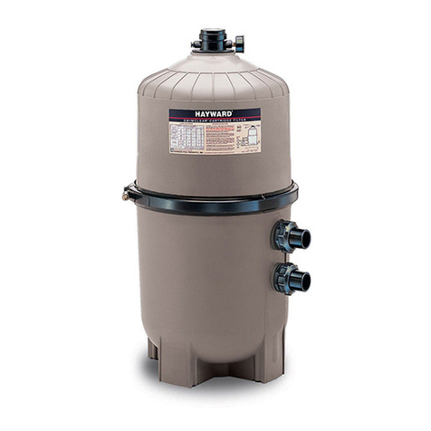
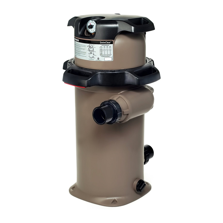
Your Hayward HCF cartridge lter combines superior water ltration with ease of operation and totally
corrosion-resistant construction. With ltration ratings to 9000 gallons (34,000 liters) per hour, they are
designed for continuous or intermittent operation, for installation above or below the pool water line, for
fresh or salt water swimming pools or spas. HCF lters utilize multiple reusable, reinforced polyester lter
cartridge elements to provide a high degree of water clarity and long lter cycles with minimum care.
2.1 Installation
WARNING
This product should be installed and serviced
onlybyaqualiedpoolprofessional.
1. The lter system should be installed on a
level concrete slab or other rigid base. Select
a well drained and vented area, one that does
not ood when it rains. Position the lter so
that the piping connections, and winter drain
are convenient and accessible for operation,
service, maintenance and winterizing.
2. Position lter body such that all operation
and safety labels are visible.
3. Position lter so the lter will drain by gravity.
4. If practical, place pump and lter in the
shade to shield it from continuous, direct
heat from the sun.
5. Connect the pool suction plumbing between the skimmer, pool suction outlet (from the pool)
and the pump.
6. Connect the pump discharge to the bottom port of the lter. FROM THE PUMP (INLET) is the
bottom port.
7. Install the plumbing from the lter (OUTLET) (return to the pool) to the pool (Top Port).
8. Do not locate pump controls over or near lter.
9. Verify water discharge from the manual air relief valve(MAR) is directed away from
electrical devices.
GENERAL INFORMATION
AREQUIRED CLEARANCE
"F" SIDE "B" ABOVE
IN CM IN CM IN CM
HCF7030C 52.5 133 18 46 28 71
