HB Products A/S –Boegekildevej 21 -8361 Hasselager –tel.: +45 8747 6200 –Email: info@hbproducts.dk (rev. 002)
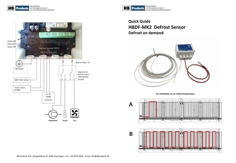
Placement of the electronics
Installing the electronics and wire along the ribs
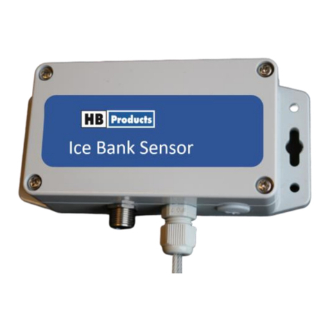
Mount the electronic part on the evaporator frame
(by the evaporator’s inlet connection) so the wire
can be freely connected parallel to the ribs
The wire with Teflon is installed parallel with the ribs in a
distance of 100-200 mm. Secure the wire with plastic strips,
so the wire is not moving when the fan is running. Be sure to
place the wire between the fins. Be sure to mount the wire
on the evaporator tubes where the ice is build up.
The wire shall be placed between the ribs and it
must be kept away from sharp edge.
The wire could be mounted as shown in the
example. It shall always be mounted where there
are ice.
The wire is terminated with a wire clip in a pre-drilled hole so
that the wire is kept under tension.
The electronics are
mounted on the
frame
The wire is secured to the
evaporator pipe with
plastic strips.
Calibration and setup of the defrost sensor
Enable the zero calibration function and push on the
button ”Send Zero/Span values” to file the entered
values.
The sensor can as well be calibrated with the digital
input on pin 5. The procedure for this is:
1) Activate the input signal in minimum 7 sec.
2) Wait 2 sec and then activate the signal once
more for 2 sec.
The SPAN should be set to 180 pF. The optimal SPAN setting will be
influenced by the length of the wire and how it is mounted. Start with
factory settings - a SPAN of 180.
Sensor sensitivity depends on the SPAN setting. A lower SPAN setting
will increase the output signal.
1) Install the HBP Tool software on the computer.
2) Connect the USB/M12 cable to a PC`s USB port.
3) Press scan for sensor and the HBDF tool opens up
The electronic part is placed on the
frame by the evaporator’s inlet
connection, since ice forms in this part
of the evaporator first.
If the output signal 4-20 mA shows 20 mA at limited ice thickness, the
SPAN should be adjusted to a higher value.
The output signal from the sensor corresponds to the ice thickness
build-up. 4 mA is equal to no ice build-up and 20 mA is equal to max
ice build-up based on the programmed SPAN area.
This example shows an actual value which correspond to an ice
thickness of 2mm. We recommend defrosting by an ice thickness of 1
to 1.5mm.
Push the button ”Send Zero/Span values” to file the entered values.
Disconnect the programming cable and install the sensor electronic.
The wire must be placed
between the ribs on the
evaporator.
The wire end is terminated
with wire termination cap.
Keep the wire away
from sharp edge.
