HB Products HBPH-MK2 User manual
INSTRUCTION MANUAL
HBPH-MK2 –pH sensor
Suited for brine/NH3 Leakage detection
DIFFERENTIAL 2-WIRE (4-20 mA) pH Sensor
TABLE OF CONTENTS
General Information ......................................................................................................................................................................2
Specifications .................................................................................................................................................................................2
Installation .....................................................................................................................................................................................3
Cold Liquid applications.................................................................................................................................................................3
Electrical connection......................................................................................................................................................................4
Storage...........................................................................................................................................................................................4
Maintenance and calibration.........................................................................................................................................................4
Calibrating the Sensor....................................................................................................................................................................5
Checking the Sensor.......................................................................................................................................................................5
Probe Cleaning...............................................................................................................................................................................6
Replacement of Salt Bridge............................................................................................................................................................7
Troubleshooting.............................................................................................................................................................................7
Parts and Accessories ....................................................................................................................................................................8
Sensor Return ................................................................................................................................................................................8
Further Information.......................................................................................................................................................................8
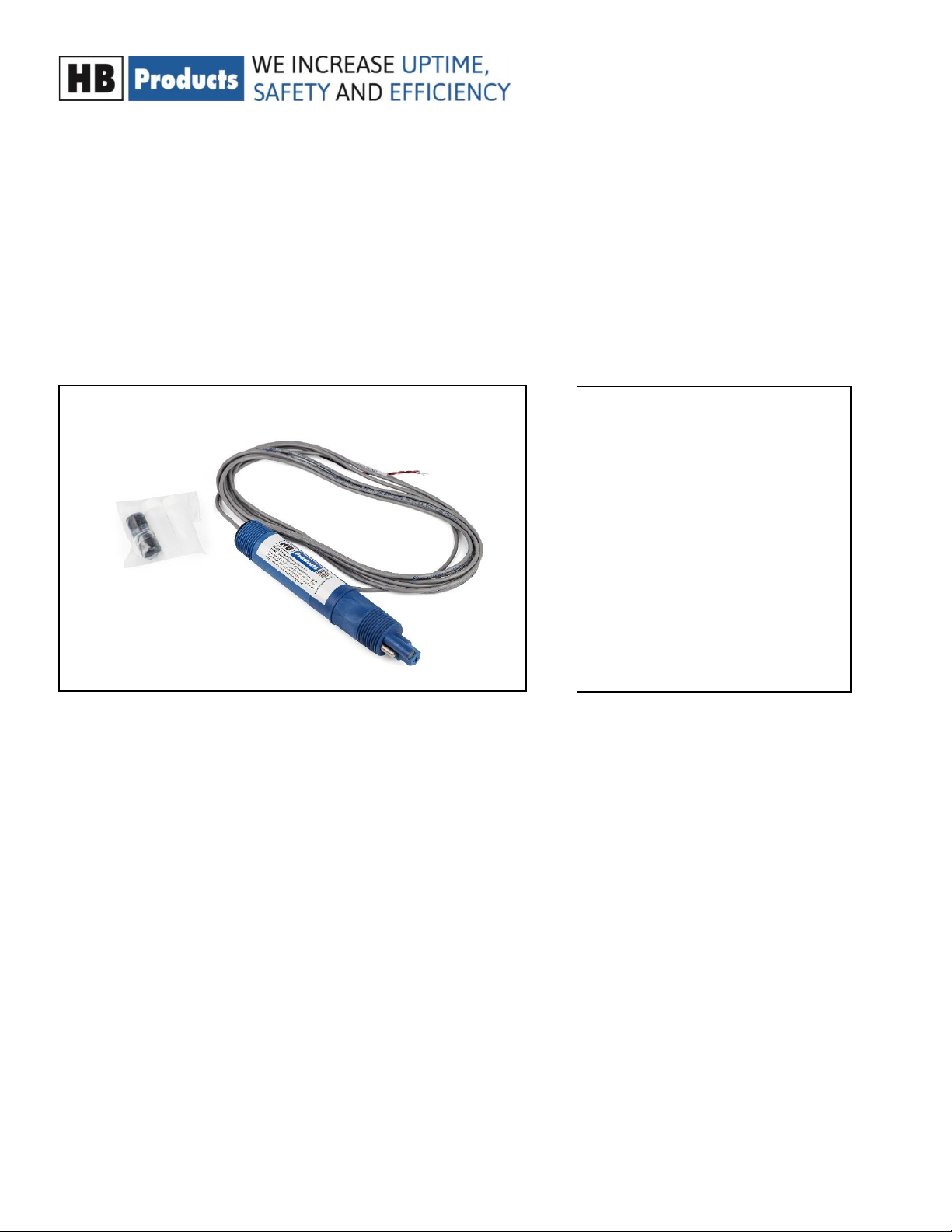
Included in the package
•Sensor with cable
•Replacement salt bridge
•Liquid for flushing and
filling
Salt bridge kit

Instructional manual- HBPH-MK2 –UK-004 Page 2
General Information
This manual covers HBPH sensor for pH measurement in brine.
The HBPH sensor features differential design for long lifetime, user serviceability and more accurate readings. In
typical installations these probes will last for years whereas the more common combination probe lasts only
months.
The sensor is a 2-wire device. It incorporates an encapsulated transmitter that outputs a 4-20 mA analog signal. It
is designed to connect directly to a PLC.
The output from a two-wire transmitter type is non-isolated and un-calibrated. The system must provide 24 VDC,
with the “low” input isolated from earth ground, and a means of calibrating for offset and span.
NOTE: Do not discard the protective cap that came with the sensor. If the sensor is removed from the process for
a longer period, thoroughly clean the sensor, put a piece of cotton ball with a few drops of water into the
protective cap and place it on the sensor. This keeps the junction from drying out which causes slow response
when the sensor is put back into operation or causes permanent damage to the sensor. Sensors should not be
left in dry lines or empty vessels for longer periods of time.
Do not store the sensor in a dry or humid location. When storing, check the protective cap regularly to make sure
the cotton ball remains moist. Improper storage of sensors voids the warranty.
Specifications
HBPH-2W-9-MKLT
Measurement Range
0 to 14.00 pH
Wetted Materials
Ryton®(PPS), glass, ceramic, titanium, Viton
Ambient Temperature
-15…+50°C
Liquid Temperature
-15…+95°C
Stability
0.03 pH/day
Resolution
0.01 pH
Sensitivity
< 0.005 pH
Output Span
1.14 mA/pH
Output Offset
12±1.0 mA @ pH 7
Mounting
1” NPT
Max. Flow Rate
3,0 m/sec (10 ft/sec)
Maximum Load
450 Ω
Temperature Limits
6,9 barg (100 psig) @ 65 °C, 2,75 barg (40 psig) @ 95°C
Power Supply Limit
24±4 VDC
Cable
4.6 m (15 ft)
Instructional manual- HBPH-MK2 –UK-004 Page 3
Installation
General Instructions
1. If the distance between the probe and the instrument is such that a direct connection is not
possible, the probe cable should be routed to a junction box with a terminal strip. The box should
be well sealed and away from corrosion danger. Be sure that you have enough slack cable to allow
for probe removal for calibration and servicing.
2. Route the interconnect cable from the
junction box to the instrument,
preferably in metal conduit. Do not run
the power cable or control cables in the
same conduit with the probe
interconnect cable.
3. Remove the protective plastic cap from
the end of the probe before placing in
service.
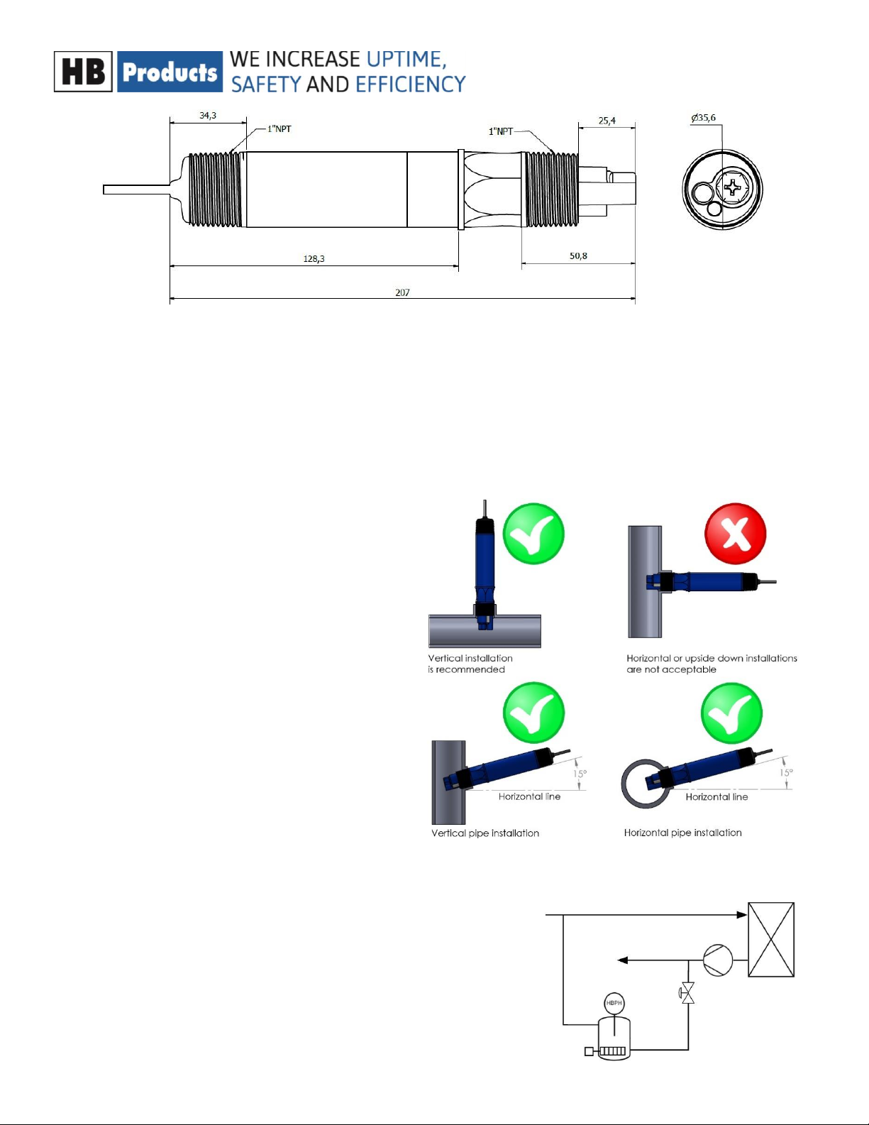
4. The sensor must be installed in direct
contact with the brine to be able to
measure the pH value. The preferred
mounting is from vertical and down to at
least 15° above horizontal. Trapped air
will disturb the measurement and must
be avoided
Cold Liquid applications
If there is a risk for brine temperatures falling below -15 °C, we
recommend using an additional system where a small amount
brine is bypassed into a pot with a built-in heating element and
thermostat controlling the temperature in a range of 0 to + 10°C .
Instructional manual- HBPH-MK2 –UK-004 Page 4
Electrical connection
HBPH probes have two wires: black and red. The red wire is to be connected to the +24 VDC terminal and
the black wire to the 24 VDC common terminal via the load in the loop.
Storage
1. Do not discard the protective cap that came with the sensor. If the sensor is removed from the
process for longer periods of time, thoroughly clean the sensor, put a piece of cotton ball with a
few drops of water into the protective cap and place it on the sensor with tape, this keeps the
junction from drying out which causes slow response when put back into operation or causes
permanent damage to the sensor. Sensors should not be left in dry lines or empty vessels for
longer periods of time.
2. Do not store the sensors in a dry or humid location. When storing, check the protective cap
regularly to make sure the cotton ball remains moist. Improper storage of sensors voids the
warranty.
Maintenance and calibration
The maintenance needed depends on your application and especially the accuracy required.
Precise measurement
If you use the sensor for a precise measurement of the pH value, you need frequent checks of the
calibration. The drift of the sensor is maximum 0.03pH per day but that is the maximum figure for a sensor
in high or low pH environments. Significant lower drift can be expected in neutral environments. Your
sensor verification frequency must reflect your needed accuracy.
Leakage detection
When used for leakage detection the required accuracy is low and annual or
biannual checks should be sufficient, especially when a warning is used. For
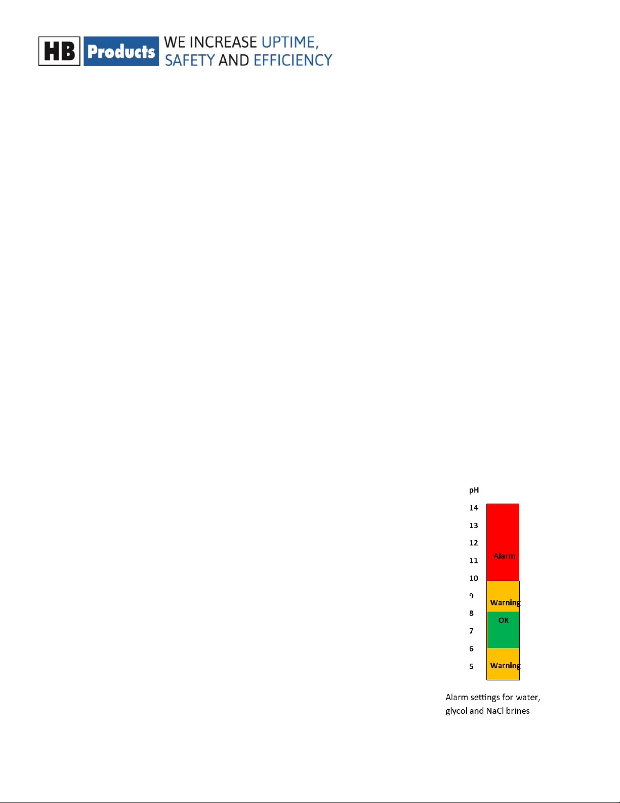
brines with a pH value between 6 and 8 it is easy to detect ammonia. Leakage of
1ml/l will increase the pH value from 7 to 10. Brines using NaCl or glycols will
have a pH value like water around 7 and they can be set up with a dual level
warning/alarm system.
A dual level warning /alarm system contains a warning level at which you need
to check your sensor calibration and a second level where you stop due to
leakage. If you have a base pH value of 7 it will make sense to use a warning for
pH above 8 and pH below 6. The second level can then be an alarm at pH=9.
With such a system it is not necessary to make frequent checks and calibrations,
however we recommend an annual or biannual check of the calibration.

Instructional manual- HBPH-MK2 –UK-004 Page 5
Calibrating the Sensor
When you receive your sensor, it is not calibrated which is needed to provide a precise result. The sensor
calibration is made in the PLC, PC, display or were you translate your mA signal into a pH value. So, the
calibration is in principle a formula which calculate your pH value based on the mA signal. The parameters
in the formula are based on measurements done with two well-known solutions. Two pH buffer solutions,
7 pH and either 4 pH or 10 pH, and a DC milliammeter are required. The calculations below are done with
pH 7 and pH 10. The process is similar for other buffer pH values.
1. Disconnect the red wire at the instrument or power supply and connect it to the multimeter (-)
black.
2. Connect the multimeter (+) red to the instrument or power supply red wire output terminal.
3. Rinse the probe and place it in 7 pH buffer solution. Allow the temperature of the buffer and probe
to stabilize at room temperature.
4. Write down the reading on the multimeter as mApH7 (in the example called: ”mApH7”). The
reading should be between 11 and 13 mA. If not, the probe is defective, or the salt bridge needs to
be replaced
5. Rinse the probe and place it in 10 pH buffer solution. Allow the temperature of the buffer and
probe to stabilize at room temperature.
6. Write down the reading on the multimeter as mApH10 (in the example called: ”mApH10”).
7. Reinstall
The pH value is calculated using this formula: pH= K * mA signal + C
Example:
The two constants can be calculated like this for 7 and 10 pH solutions:
The noted currents for the two solutions in the example are: mApH7 =11.08mA and mApH10=14.47mA
K = (pH value1-pH value2) / (mApH7 - mApH10) =7 - 10 / 11.08 - 14.47 = -3/-3.39 =0.885
C = pH value1 - K* mApH7 = 7 –0,885 *11.08 = - 2.81
The formula looks like this: pH = 0.885 * mA signal - 2.81
Checking the Sensor
The operation of the 2-wire, 4-20 mA sensor can be checked by a few simple measurements. Two pH buffer
solutions, 7 pH and either 4 pH or 10 pH, and a DC milliammeter are required.

Instructional manual- HBPH-MK2 –UK-004 Page 6
1. Disconnect the red wire at the instrument or power supply and connect it to the multimeter (-)
black.
2. Connect the multimeter (+) red to the instrument or power supply red wire output terminal.
3. Rinse the probe and place it in 7 pH buffer. Allow the temperature of the buffer and probe to
stabilize at room temperature.
4. Check the offset of the probe by reading the multimeter. The reading should be between 11 and
13 mA. If not, the probe is defective, or the salt bridge needs to be replaced. If the offset is OK,
please note the exact reading and proceed to the next step.
5. Rinse the probe and place it in 4 pH or 10 pH buffer. Allow the temperature of the probe and
buffer to stabilize at room temperature. Now check the span of the probe by reading the
multimeter. If the probe is in 4 pH buffer, the reading should be between 2.75 and 3.5 lower than
the reading obtained in 7 pH buffer.
6. If the probe is in 10 pH buffer, the reading should be between 2.75 and 3.5 higher than the reading
obtained in 7 pH buffer.
7. If this test is not satisfied the probe is defective, or the salt bridge needs to be replaced.
8. If the span of the probe drops below 2.75mA than the probe still can be used. Adjustments will
have to be made to the receiving device to compensate for the low span.
Probe Cleaning
The probe should be kept reasonably clean to avoid measurement errors. Frequency of cleaning can only
be determined by experience. To clean proceed as follows:
1. Rinse with clean warm water.
2. Soak the end of the probe in warm water and dish detergent for 3 or 4 minutes.
3. Brush the end of the probe, particularly the three electrodes with a soft bristle brush such as a
toothbrush. Take care not to scratch the glass electrode.
4. If the probe is still not clean, it may have to be cleaned with acid. CAUTION: Do not acid clean
probes used in processes containing cyanide solutions. Some experimentation may be required to
determine the most suitable acid for your process. Use the most dilute acid, which is effective.
Normally 10 parts of water to one-part muriatic acid (HCl) is sufficient. Do not use hydrofluoric
acid.
5. Soak the probe for not more than 5 minutes in the chosen acid; then rinse thoroughly with clean
warm water and soak in water for 3-5 minutes.
6. Calibrate the system in accordance with the instrument instruction manual.
Instructional manual- HBPH-MK2 –UK-004 Page 7
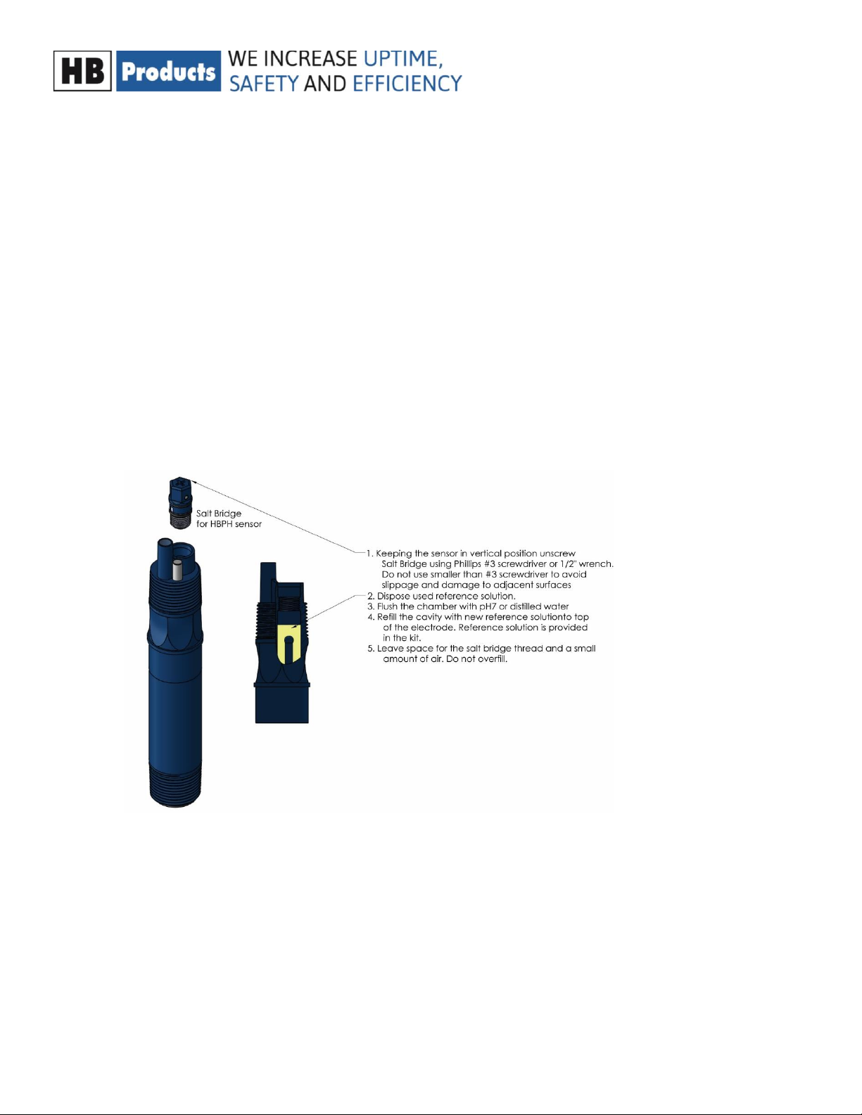
Replacement of Salt Bridge
1. If the system cannot be calibrated after cleaning the probe, it may be necessary to replace the
standard cell solution and/or the salt bridge. A salt bridge kit is available from HB Products for this
purpose.
2. Hold the probe vertically electrodes up. Remove the used salt bridge. The salt bridge is a
hexagonal-shaped capsule that can be removed using a #3 Phillips screwdriver. ½” wrench or pliers
can also be used.
3. Discard the used salt bridge.
4. Dispose of the used solution inside the bridge chamber and rinse with pH 7 solution or distilled
water.
5. Refill the chamber with a reference solution supplied with the salt bridge, up to the tip of the
electrode inside the chamber. DO NOT OVERFILL. It is important to leave space for the salt bridge
thread and a small amount of air.
6. Screw the new salt bridge into the cavity until finger tight. If needed, use a #3 Phillips screwdriver
to make sure that the salt bridge edges are aligned with the front of the probe face.
Troubleshooting
A sensor that is not functioning properly will output a current that is out of range of the specifications
listed in Checking Sensor section.
The change in output with calibration standard constitutes the span. For a pH probe, the span between
pH 4 and pH 7 or between pH 7 and pH 10 should be between 2.75 and 3.5 mA.

Instructional manual- HBPH-MK2 –UK-004 Page 8
Issue:
Likely cause:
Troubleshooting:
The output of the sensor DOES
change between pH buffers but not
as good (quick) as it should (or did)
before.
Span less than 0.9mA/pH
The process electrode (glass bulb) is
coated with scaling or biofouling
A coated electrode will create a
narrower span
If the coating is from scaling then soaking the
probe in a weak acid (e.g. vinegar or 0.1M
HCl) will remove the scale. If the coating is
from fouling then soaking the probe in
bleach will clear it.
The offset is outside of spec:
11mA > pH7 > 13mA
The reference solution has been
contaminated with the process or
the salt bridge has fouled
Salt bridge replacement is needed
The pH reading DOES NOT change
at all when changing from one
calibration solution to another
The process electrode is inoperable
(likely cracked or broken) or the
printed circuit board (PCB) has
failed
Sensor is non-repairable
The output is outside of 4-20mA
The sensor electronic has failed
Sensor is non-repairable
Parts and Accessories
Description
Part #
3-pack salt bridge replacement kit
HBPH-SB-KIT
Controller for pH Sensor
HBPH-C1
Controller for pH Sensor
HBPH-C1-ENC
Sensor Return
If you are returning a probe for inspection, enclose description of the problem. Pack the probe adequately
to avoid damage to the glass electrode and ensure that it will not be exposed to temperatures below -15°C.
HB Products cannot be responsible for shipping damage or for damage due to frozen electrodes. For safety
reasons, HB Products cannot accept probes which have not been thoroughly cleaned to remove all process
material and put a piece of cotton ball with a few drops of water into the protective cap and place it on the
sensor with tape to prevent it from drying out.
Further Information
For further information, please visit our website, www.hbproducts.dk, or send an email to: s[email protected]k.
HB Products A/S –Bøgekildevej 21 –DK8361 Hasselager –support@hbproducts.dk –www.hbproducts.dk
This manual suits for next models
2
Table of contents
Other HB Products Accessories manuals

HB Products
HB Products HBLT User manual

HB Products
HB Products HBDF User manual

HB Products
HB Products HBLC User manual

HB Products
HB Products HBCP User manual

HB Products
HB Products SLCD-M1/_Ex Series User manual

HB Products
HB Products HBIB Use and care manual

HB Products
HB Products HBOC User manual

HB Products
HB Products HBX Vapor Quality sensor Operator's manual

HB Products
HB Products HBLT-WIRE User manual

HB Products
HB Products HBDF-MK2 User manual


