HBX ECO-0550 User manual

HBX Control Systems Inc.
Installation Manual
Central Processing Unit 0550
Version 2.00
ECO-0550

Control Systems Inc.
Comfort
Control
Innovation
HBX ECO-0550 Geothermal Control
Version 1.11
Table of Contents
Table of Contents
Control Systems Inc.
Comfort
Control
Innovation
HBX ECO-0550 Geothermal Control
Version 1.11
Table of Contents
TABLE OF CONTENTS
Introduction ............................................................................................ 1-3
Safety Symbols & Warnings ....................................................................1
Receipt & Inspection .............................................................................. 1
Description ...............................................................................................1
QR Code.................................................................................................... 1
Technical Data and Dimensions ........................................................... 2
Wiring & Installation ............................................................................... 3
Wiring ....................................................................................................... 3
Installation ................................................................................................ 3
Programming ECO-0550 .........................................................................4-5
Navigating the ECO-0550........................................................................ 4
Control Mode............................................................................................ 4
Setup Menu............................................................................................... 5
Geothermal Mode Programming........................................................... 6-13
Multicolour backlit display....................................................................... 6
Screen Colours.......................................................................................... 6
Status Screen............................................................................................. 6
Heat Pump Setup......................................................................................7
Tank Setup................................................................................................. 8-11
Backup Setup............................................................................................ 12
EcoSwitch Energy Clock.......................................................................... 13-15
Priority Setup.............................................................................................. 15
WiSetup....................................................................................................16
Connecting to a Wireless Network......................................................... 17-18
Adding Devices........................................................................................ 19
Sample Wiring and Diagrams ............................................................... 20-22
Troubleshooting Guide............................................................................ 23-24
Warranty Information .............................................................................. 25

HBX ECO-0550 Geothermal Control
Version 2.00
© HBX Control Systems Inc. 2018 Page 1
Control Systems Inc.
Comfort
Control
Innovation
HBX ECO-0550 Geothermal Control
Version 1.11
Table of Contents
HBX ECO-0550 GEOTHERMAL CONTROLLER
INTRODUCTION
This manual will help with the installation, parameter setting, troubleshooting
and general maintenance requirements for the controller. To guarantee the
safeandreliableoperationofthiscontrol,youmustrstreadthismanualin
detail and take particular note to any and all warnings or caution directives
prior to connecting to AC power.
Please consult and install the geothermal appliance in accordance with
manufacture’s recommendations.
DESCRIPTION
The ECO-0550 is designed to be a stand-alone Outdoor Reset Control
device. The purpose and function of the ECO-0550 is to provide control for
Geothermal applications. It can manage single tank applications as well as
applications with seperate hot and cold tanks.
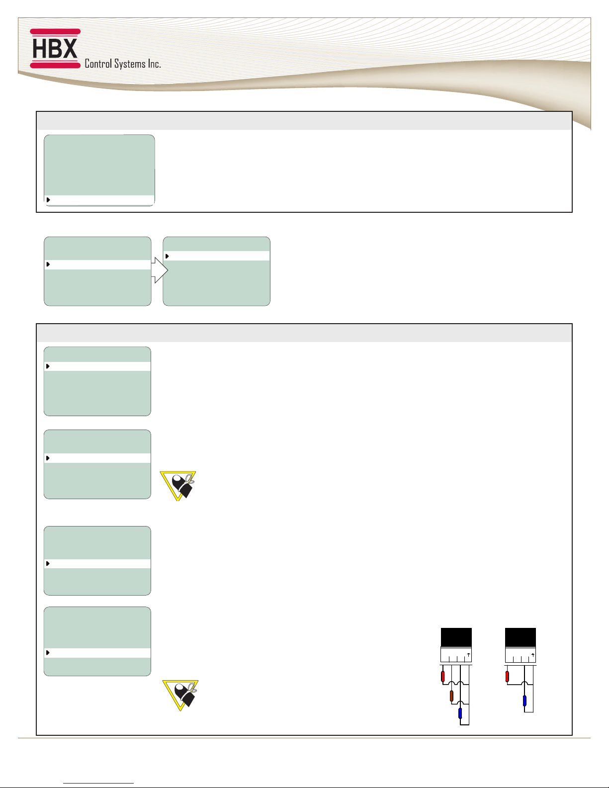
SAFETY SYMBOLS & WARNINGS
Extreme Hazard
This action poses a serious threat that could
result in personal injury or death, as well as
permanent damage to the equipment.
Proceed with caution.
Moderate Hazard
This action may cause personal injury or have
adverse effects on the installation process if
handled incorrectly.
Disconnect Power Source
The presence of low voltage(24VAC) or high
voltage(120VAC) could result in personal injury
or permanent damage to components or
equipment.
Point of Interest
This point claries pertinent information, or
brings your attention to an action that may
have adverse effects on the installation
process.
Drawing Reference
Refertothespeciedelectricalormechanical
drawing at the back of the manual.
Only suitably qualied individuals with formal
training in electrical and Geothermal controls
should attempt the installation of this equipment.
Incorrect wiring and installation will affect the
warranty provided with this unit. Wiring must be
completed in accordance with the codes and
practices applicable to the jurisdiction for the
actual installation.
Use only copper conductor supply wire suitable
for at least 105 °C
The HBX ECO-0550 is a microprocessor based
controller and as such is not to be regarded as a
safety (limit) control. Please consult and install
the heating or cooling appliance in accordance
with the manufacturer’s recommendations.
RECEIPT & INSPECTION
After receiving, inspect the unit for any possible
physical damage that may have occurred during
transportation.
After unpacking the unit make sure the box contains:
•1 x Remote Outdoor sensor (Part #OUT-0100)
•2 x Universal sensors (Part #029-0022)
•1 x Terminal Screwdriver (2.5mm)
•2 x Cable ties
•1 x Manual
WARNING: This product can expose you to chemicals
including lead, which is known to the State of California to
cause cancer and birth defects or other reproductive harm.
For more information go to www.P65Warnings.ca.gov.
!

HBX ECO-0550 Geothermal Control
Version 2.00
Page 2
DIMENSIONS
TECHNICAL DATA & DIMENSIONS
TECHNICAL DATA
Specications:
3 x Thermistor Input
(10K Ohm)
2 x Miscellaneous Input Signal
3 x Relay Outputs (240VAC 5Amps) Dry
Contacts
1 x 2Amp Dry Contact
Input: 120VAC +/- 10% 50/60Hz 15A Max
FCC ID: 2AHMR-ESP12S
Weight:
0.408Kg
Dimensions:
100mm W x 168mm H x 70mm
ETL Listings:
Meets CSA C22.2 No. 24
Meets UL Standard 873
ETL Control No. 3068143
Storage:
50°F to 104°F (10ºC to 40ºC)
ECO-0550
Central Processing Unit
Relays:
240VAC 5A Max
Input:
120VAC 15A Max
ENTER
ECO
Input
Signals (4)
Heat Pump Outdoor
Sensor
120
VAC
Relay
Outputs (2)
Reversing
Valve
Tank
Sensor (2)
66 mm
(2.60 in) (2.76 in)
70.19 mm
Side View Front View Rear View
Top View
188 mm
(7.40 in) (6.57 in)
(4.76 in) (3.94 in)
121 mm
167 mm
100 mm
Bottom View

HBX ECO-0550 Geothermal Control
Version 2.00
© HBX Control Systems Inc. 2018 Page 3
1, 2: Demand Signal 1
Apply heat demand from a dry contact, or 24VAC.
3, 4: Demand Signal 2
Apply cool demand from a dry contact, or 24VAC.
5, 6: Heat Pump 1
Heat Pump 1 Output.
Sensor Inputs
7, 10: Hot Tank temperature in dual tank mode, or
Tank Temperature in single tank mode.
8, 10: Cold Tank temperature. If the cold tank sensor
is not connected, the control assumes single tank
operation.If connected, the control will operate in
dual tank mode.
9, 10: Outdoor temperature.
14, 15: Relay 1
This relay is generally a second Heat Pump, or can be
used as System Pump output.
16, 17: Relay 2
Generally used as a Third stage or Backup Boiler.
18, 19: Relay 3
Used as a Reversing Valve and/or 3 way diverting
valves.
(Relays 1, 2 and 3 are dry contacts and rated for a
maximum of 5 Amps.)
5 A
RL
1
RL
1514
1
5 A
RL
2
RL
1716
2
HBX
GR
120
13
N
L
1211
11
TM
32
8
TM TM
7 9 10
BL
1
BL
65
1
2A
1-10v
+ - DO NOT
CONNECT
POWER
HERE
12
DS
12
2
DS DS
1 3 4
DO NOT
CONNECT
POWER
HERE
DS
5 A
RL
2
RL
1918
2
ECO-0550 Central Processing Unit
Demand Input 1
Demand Input 2
Heat Pump Contacts
Sensor Inputs
Relay 3
Relay 2
Relay 1
Supply Power 120 VAC
WIRING AND INSTALLATION
Wiring
All signal wiring must be with a minimum of 18AWG wire at a maximum of 500ft.
Installation
The ECO-0550 is designed to be wall mounted or installed in a separate
electrical enclosure. The unit should be mounted inside and protected from
falling water and high humidity conditions. With all the covers in place it is
designed to protect any individual from accidental electrical shock. It is not
suitable for installation in hazardous locations and should not be placed
closetoanyelectromagneticelds.
•Identify the four mounting holes on the ECO-0550, mark on the wall the
desired location of mounting.
•Predrill, anchor and fasten four screws for mounting.
•Hang ECO-0550 and fasten tight to desired locations
•Complete wiring connections in accordance with terminal locations.
Mounting Holes
24VAC
MAX

HBX ECO-0550 Geothermal Control
Version 2.00
Page 4
Geothermal Mode
Programming for this mode can be found on pages 7 through 15. This mode is used
when running heat pumps/chillers or geothermal related installations. The control
will run up to 3 stages of heat pumps, a reversing valve for heating and cooling
applications, as well as single or dual tanks. This mode also allows for a built-in backup
feature.
CONTROL MODE
The programming instructions for the ECO-0550 are currently selectable in the mode listed below. When the
controlisrstpluggedinyouareaskedtoselectwhichcontrolmodeyouwouldlikeyourECO-0550tooperate
in.Toselectyourcontrolmodesimplyusethe▲or▼buttonstoselectthecorrectmodethenwaitve
seconds to accept your selection.
NAVIGATING THE ECO-0550
All programming steps within the ECO-0550
are achieved by using the three buttons (and
combination thereof) located below the screen.
The▼buttonisusedtoscrolldowninmenuscreens
anddecreaseavaluewithinspecicoptions.
The▲buttonisusedtoscrollupinmenuscreens
andincreaseavalueinspecicoptions.
The ENTER button is used to access the setpoint
menu and select a setting.
ECO-0550
Central Processing Unit
Relays:
240VAC 5A Max
Input:
120VAC 15A Max
ENTER
ECO
Input
Signals (4)
Heat Pump Outdoor
Sensor
120
VAC
Relay
Outputs (2)
Reversing
Valve
Tank
Sensor (2)
CHOOSE CONTROL TYPE
1) GEOTHERMAL
1.10

HBX ECO-0550 Geothermal Control
Version 2.00
© HBX Control Systems Inc. 2018 Page 5
SETUP MENU
The SETUP menu is used for entering the design values, as well as assign different control options. To access the
setup menu, push the ENTERbuttonontheSTATUSscreen.Usethe▲or▼buttonstoscrollthroughthevarious
settings.
To select a parameter, align the cursor arrow with the desired parameter and press the ENTER button. The
arrowwillbecomesolid►,whichindicatesthataparameterhasbeenselected.
Adjustthesettingtothedesiredvaluewiththe▲or▼buttons.Oncethecorrectvalueisset,pushtheENTER
button. This will deselect the parameter.
To go to the previous screen, push and hold the ENTER button. If the SETUP menu is left for more than 90
seconds, the display will change to the STATUS screen and the control will resume operation.
SETUP MENU 2.00
1) HEAT PUMPS
2) TANKS
3) BACKUP
4) ENERGY CLOCK
5) PRIORITY
6) WIFI
COLD
°HEAT PUMP SETUP
1) HP STAGES
2) LAG TIME
3) ROTATE TIME
4) ROT CYCLES
5) OFF STAGING
6) °C OR °F
2
3m
OFF
OFF
ON
°F
STATUS
HOT TANK
COLD TANK
OUTDOOR
HP1
ON
HD CD WWSD CWSD
10:00AM
TARGET
HP2
ON
BKUP
ON
REV VL
OFF
105°F
95°F
10°F
110°F
45°F

HBX ECO-0550 Geothermal Control
Version 2.00
Page 6
GEOTHERMAL MODE
Status Screen
STATUS
HOT TANK
COLD TANK
OUTDOOR
HP1
ON
HD CD WWSD CWSD
10:00
AM
TARGET
HP 2
ON
BKUP
OFF
REV VL
ON
105°F
95°F
10°F
110°F
45°F
Heat Demand
Cooling Demand
Warm Weather Shut Down
Current Time
Cold Weather Shut Down Current Temperatures
Hot Tank Target
WiFi Indicator
Cold Tank Target
Multicolour backlit Display
The Multicolour Backlit Display is one of the key features of the HBX Controls stand-alone ECO-0550 Control.
Depending on which mode of operation is selected the screen color will change to indicate information about
the status of the system.
Screen Colors
Light Blue - No Heat Demand
Red - Demand and heat pumps running (Heating Mode)
Green - Demand ON, no heat pumps running
Dark Blue - Demand ON and heat pumps running (Cooling Mode)
Purple - Demand ON and Backup Only running (EcoSwitch Mode)
5 A
RL
1
RL
1514
1
5 A
RL
2
RL
1716
2
HBX
GR
120
13
N
L
1211
11
TM
32
8
TM TM
7 9 10
BL
1
BL
65
1
2A
1-10v
+ - DO NOT
CONNECT
POWER
HERE
12
DS
12
2
DS DS
1 3 4
DO NOT
CONNECT
POWER
HERE
DS
5 A
RL
2
RL
1918
2
ECO-0550 Central Processing Unit
Heat Demand
Cooling Demand
Heat Pump 1
Hot Tank Sensor/
Cold Tank Sensor/
Outdoor Sensor
Reversing Valve
Heat Pump 3/
Backup Boiler
System Pump/
Heat Pump 2
Supply Power 120 VAC
24VAC
MAX

HBX ECO-0550 Geothermal Control
Version 2.00
© HBX Control Systems Inc. 2018 Page 7
GEOTHERMAL MODE PROGRAMMING GUIDE
1) HEAT PUMPS
SETUP MENU 2.00
1) HEAT PUMPS
2) TANKS
3) BACKUP
4) ENERGY CLOCK
5) PRIORITY
6) WIFI
COLD
HEAT PUMP SETUP
1) HP STAGES
2) LAG TIME
3) ROTATE TIME
4) ROT CYCLES
5) OFF STAGING
6) °C OR °F
1
3m
OFF
OFF
ON
°F
HEAT PUMP SETUP
1) HP STAGES
2) LAG TIME
3) ROTATE TIME
4) ROT CYCLES
5) OFF STAGING
6) °C OR °F
1
3m
OFF
OFF
ON
°F
HEAT PUMP SETUP
1) HP STAGES
2) LAG TIME
3) ROTATE TIME
4) ROT CYCLES
5) OFF STAGING
6) °C OR °F
1
3m
OFF
OFF
ON
°F
HEAT PUMP SETUP
1) HP STAGES
2) LAG TIME
3) ROTATE TIME
4) ROT CYCLES
5) OFF STAGING
6) °C OR °F
1
3m
OFF
OFF
ON
°F
HEAT PUMP SETUP
1) HP STAGES
2) LAG TIME
3) ROTATE TIME
4) ROT CYCLES
5) OFF STAGING
6) °C OR °F
1
3m
OFF
OFF
ON
°F
HEAT PUMP SETUP
1) HP STAGES
2) LAG TIME
3) ROTATE TIME
4) ROT CYCLES
5) OFF STAGING
6) °C OR °F
1
3m
OFF
OFF
ON
°F
HEAT PUMP SETUP
Stages
This setting will allow you to select the number of heat pump stages that are
attached to the control.
If Backup is being used, you can only have a maximum of 2 stages.
(1 to 3) Default: 1
Lag Time
When the heat pump is set for more than 1 stage, this setting will be set for the
minimum lag time between heat pump stages. This is a time delay between stages.
Even if the differential has been exceeded this time must elapse before that stage
can come on.
(1m to 240m) Default: 3m
Rotate Time
The time of rotation between heat pumps. This setting is in hours of run time. This
meansthattheheatpumpsaregoingtorotatewhentherstheatpumpexceeds
the second by the rotate time.
(OFF/1H to 99H) Default: OFF
Rotate Cycles
Set the number of cycles at which you would like to rotate the heat pumps. One
cycle is described as the heat pump going on and then off.
(OFF/1 to 240) Default: OFF
Off Staging
This feature is used to set how you would like to stage the heat pumps off. If set to ON
the heatpumps will stage off normally, based off of tank temperature and differential
settings. If set to OFF the heat pumps will all stage off at the same time, based off of
tank temperature and differential settings.
(OFF/ON) Default: ON
Heat Pump Setup
Thissettingisusedtoconguretheheatpumpstagingcomponentinyoursystem.

HBX ECO-0550 Geothermal Control
Version 2.00
Page 8
2) TANK SETUP
TANK SETTINGS
1) HOT TANK
2) COLD TANK
3) CWSD/WWSD TIME 0H
SETUP MENU 1.10
1) HEAT PUMPS
2) TANKS
3) BACKUP
4) ENERGY CLOCK
5) PRIORITY
6) WIFI
COLD
HOT TANK SETUP
1) WWSD
2) OUTDOOR
3) HOT DIFF
4) TANK TEMP
65°F
OFF
6°F
115°F
HOT TANK SETUP
1) WWSD
2) OUTDOOR
3) HOT DIFF
4) TANK TEMP
65°F
OFF
6°F
115°F
HOT TANK SETUP
1) WWSD
2) OUTDOOR
3) HOT DIFF
4) TANK TEMP
65°F
OFF
6°F
115°F
HOT TANK SETUP
1) WWSD
2) OUTDOOR
3) HOT DIFF
4) MIN TANK TEMP
5) MAX TANK TEMP
65°F
11°F
6°F
80°F
115°F
HOT TANK SETUP
1) WWSD
2) OUTDOOR
3) HOT DIFF
4) MIN TANK TEMP
5) MAX TANK TEMP
65°F
11°F
6°F
80°F
115°F
HOT TANK SETUP
1) WWSD
2) OUTDOOR
3) HOT DIFF
4) MIN TANK TEMP
5) MAX TANK TEMP
65°F
11°F
6°F
80°F
115°F
HOT TANK SETUP
1) WWSD
2) OUTDOOR
3) HOT DIFF
4) MIN TANK TEMP
5) MAX TANK TEMP
65°F
11°F
6°F
80°F
115°F
HOT TANK SETUP
1) WWSD
2) OUTDOOR
3) HOT DIFF
4) MIN TANK TEMP
5) MAX TANK TEMP
65°F
11°F
6°F
80°F
115°F
HOT TANK SETUP
1) WWSD
2) OUTDOOR
3) HOT DIFF
4) TANK TEMP
65°F
OFF
6°F
115°F
HOT TANK SETUP WITHOUT OUTDOOR RESET
Warm Weather Shut Down
This setting is used to set the temperature in which the ECO-0550 will go into WWSD. If
the system rises above this temperature, the system will be shut off. In WWSD the heat
pumps and backup boiler will shut off.
(OFF/35°F to 119°F) Default: 65°F
Hot Tank Differential
Set this temperature to be the desired hot tank differential. A differential of 4°F will
allow for 2 degrees above and/or 2 degrees below the desired temperature before a
demand is present.
(2°F to 100°F) Default: 6°F
Tank Target Temperature
When a heat demand is present and the control is not
in WWSD, the control will target this temperature for
heating.
(50°F to 200°F) Default: 115°F
If there is no thermistor attached to pins 8 and
9, the control assumes single tank operation.
Hot Tank Setup
This setting is used to set the desired temperature in the hot
tank when there is a heat demand present.
Outdoor Temperature (Design)
Thisisusedintheoutdoorresetdesigncalculation.Thisoptionshouldbesettoreect
yourspeciccityorregion.
With this option enabled, the Tank Temperature setting will be replaced by
Min Tank and Max Tank Temperature settings.
(OFF/0°F to 119°F) Default: OFF
C
R
L
N
120 V AC
24 V AC
Cold
Tank
Hot
Tank
5 A
RL
1
RL
1514
1
5 A
RL
2
RL
1716
2
Central Processing Unit
ECO-0550
HBX
GR
120
13
N
L
1211
11
TM
32
8
TM TM
7 9 10
BL
1
BL
65
1
2A
DO NOT
CONNECT
POWER HERE
12
DS
12
2
DS DS
1 3 4
DO NOT
CONNECT
POWER HERE
DS
5 A
RL
2
RL
1918
2
Outdoor
THM-0200
HBX
RL
2
RL
32
2 2
24V AC
109
2
TH
2
TH
87
3
Thermostat
RL
1
RL
54
1
2 A
DO NOT CONNECT
POWER HERE
TH
1
6
RL
1
2 A
1
HP 1 Backup Rev Valves
System
Pump
C
R
L
N
120 V AC
24 V AC
5 A
RL
1
RL
1514
1
5 A
RL
2
RL
1716
2
Central Processing Unit
ECO-0550
HBX
GR
120
13
N
L
1211
11
TM
32
8
TM TM
7 9 10
BL
1
BL
65
1
2A
DO NOT
CONNECT
POWER HERE
12
DS
12
2
DS DS
1 3 4
24V AC
MAX
DS
5 A
RL
2
RL
1918
2
HP 1 HP 3 Rev Valves
HP 2
Tank
Sensor
4 Wire Thermostat
YRC
W
Outdoor
Sensor
Dual Tank
Setup
Single Tank
Setup
1) HEAT PUMPS (CONT.)
SETUP MENU 2.00
1) HEAT PUMPS
2) TANKS
3) BACKUP
4) ENERGY CLOCK
5) PRIORITY
6) WIFI
COLD
HEAT PUMP SETUP
1) HP STAGES
2) LAG TIME
3) ROTATE TIME
4) ROT CYCLES
5) OFF STAGING
6) °C OR °F
1
3m
OFF
OFF
ON
°F
HEAT PUMP SETUP
1) HP STAGES
2) LAG TIME
3) ROTATE TIME
4) ROT CYCLES
5) OFF STAGING
6) °C OR °F
1
3m
OFF
OFF
ON
°F
HEAT PUMP SETUP
1) HP STAGES
2) LAG TIME
3) ROTATE TIME
4) ROT CYCLES
5) OFF STAGING
6) °C OR °F
1
3m
OFF
OFF
ON
°F
HEAT PUMP SETUP
1) HP STAGES
2) LAG TIME
3) ROTATE TIME
4) ROT CYCLES
5) OFF STAGING
6) °C OR °F
1
3m
OFF
OFF
ON
°F
HEAT PUMP SETUP
1) HP STAGES
2) LAG TIME
3) ROTATE TIME
4) ROT CYCLES
5) OFF STAGING
6) °C OR °F
1
3m
OFF
OFF
ON
°F
HEAT PUMP SETUP
1) HP STAGES
2) LAG TIME
3) ROTATE TIME
4) ROT CYCLES
5) OFF STAGING
6) °C OR °F
1
3m
OFF
OFF
ON
°F
Celsius or Fahrenheit
This setting is used to set the temperatures displayed on the control in either Celsius or
Fahrenheit.
Default: °F
HEAT PUMP SETUP
TANK SETTINGS
1) HOT TANK
2) COLD TANK
3) CWSD/WWSD TIME 0H
SETUP MENU 1.10
1) HEAT PUMPS
2) TANKS
3) BACKUP
4) ENERGY CLOCK
5) PRIORITY
6) WIFI
COLD
HOT TANK SETUP
1) WWSD
2) OUTDOOR
3) HOT DIFF
4) TANK TEMP
65°F
OFF
6°F
115°F
HOT TANK SETUP
1) WWSD
2) OUTDOOR
3) HOT DIFF
4) TANK TEMP
65°F
OFF
6°F
115°F
HOT TANK SETUP
1) WWSD
2) OUTDOOR
3) HOT DIFF
4) TANK TEMP
65°F
OFF
6°F
115°F
HOT TANK SETUP
1) WWSD
2) OUTDOOR
3) HOT DIFF
4) MIN TANK TEMP
5) MAX TANK TEMP
65°F
11°F
6°F
80°F
115°F
HOT TANK SETUP
1) WWSD
2) OUTDOOR
3) HOT DIFF
4) MIN TANK TEMP
5) MAX TANK TEMP
65°F
11°F
6°F
80°F
115°F
HOT TANK SETUP
1) WWSD
2) OUTDOOR
3) HOT DIFF
4) MIN TANK TEMP
5) MAX TANK TEMP
65°F
11°F
6°F
80°F
115°F
HOT TANK SETUP
1) WWSD
2) OUTDOOR
3) HOT DIFF
4) MIN TANK TEMP
5) MAX TANK TEMP
65°F
11°F
6°F
80°F
115°F
HOT TANK SETUP
1) WWSD
2) OUTDOOR
3) HOT DIFF
4) MIN TANK TEMP
5) MAX TANK TEMP
65°F
11°F
6°F
80°F
115°F
HOT TANK SETUP
1) WWSD
2) OUTDOOR
3) HOT DIFF
4) TANK TEMP
65°F
OFF
6°F
115°F

HBX ECO-0550 Geothermal Control
Version 2.00
© HBX Control Systems Inc. 2018 Page 9
TANK SETTINGS
1) HOT TANK
2) COLD TANK
3) CWSD/WWSD TIME 0H
SETUP MENU 1.10
1) HEAT PUMPS
2) TANKS
3) BACKUP
4) ENERGY CLOCK
5) PRIORITY
6) WIFI
COLD
HOT TANK SETUP
1) WWSD
2) OUTDOOR
3) HOT DIFF
4) TANK TEMP
65°F
OFF
6°F
115°F
HOT TANK SETUP
1) WWSD
2) OUTDOOR
3) HOT DIFF
4) TANK TEMP
65°F
OFF
6°F
115°F
HOT TANK SETUP
1) WWSD
2) OUTDOOR
3) HOT DIFF
4) TANK TEMP
65°F
OFF
6°F
115°F
HOT TANK SETUP
1) WWSD
2) OUTDOOR
3) HOT DIFF
4) MIN TANK TEMP
5) MAX TANK TEMP
65°F
11°F
6°F
80°F
115°F
HOT TANK SETUP
1) WWSD
2) OUTDOOR
3) HOT DIFF
4) MIN TANK TEMP
5) MAX TANK TEMP
65°F
11°F
6°F
80°F
115°F
HOT TANK SETUP
1) WWSD
2) OUTDOOR
3) HOT DIFF
4) MIN TANK TEMP
5) MAX TANK TEMP
65°F
11°F
6°F
80°F
115°F
HOT TANK SETUP
1) WWSD
2) OUTDOOR
3) HOT DIFF
4) MIN TANK TEMP
5) MAX TANK TEMP
65°F
11°F
6°F
80°F
115°F
HOT TANK SETUP
1) WWSD
2) OUTDOOR
3) HOT DIFF
4) MIN TANK TEMP
5) MAX TANK TEMP
65°F
11°F
6°F
80°F
115°F
HOT TANK SETUP
1) WWSD
2) OUTDOOR
3) HOT DIFF
4) TANK TEMP
65°F
OFF
6°F
115°F
HOT TANK SETUP WITH OUTDOOR RESET
Warm Weather Shut Down
This setting is used to set the temperature in which the ECO-0550 will go into WWSD. If
the system rises above this temperature, the system will be shut off. In WWSD the heat
pumps and backup boiler will shut off.
(OFF/35°F to 119°F) Default: 65°F
Outdoor Temperature (Design)
Thisisusedintheoutdoorresetdesigncalculation.Thisoptionshouldbesettoreect
yourspeciccityorregion.
(OFF/-40°F to 120°F) Default: OFF
Hot Tank Differential
Set this temperature to be the desired hot tank differential. A differential of 4°F will
allow for 2 degrees above and/or 2 degrees below the desired temperature before a
demand is present.
(2°F to 100°F) Default: 6°F
Minimum Tank Temperature
This setting is the bottom of the heat curve. The target will hit this temperature as the
Outdoor Temperature approaches the WWSD.
(50°F to 200°F) Default: 80°F
Maximum Tank Temperature
This setting is the top of the heat curve. The target will hit this temperature as the
Outdoor Temperature approaches the Design Outdoor Temperature.
(50°F to 200°F) Default: 115°F

HBX ECO-0550 Geothermal Control
Version 2.00
Page 10
TANK SETTINGS
1) HOT TANK
2) COLD TANK
3) CWSD/WWSD TIME 0H
SETUP MENU 2.00
1) HEAT PUMPS
2) TANKS
3) BACKUP
4) ENERGY CLOCK
5) PRIORITY
6) WIFI
COLD
COLD TANK SETUP
1) CWSD
2) OUTDOOR
3) COLD DIFF
4) TANK TEMP
75°F
OFF
8°F
45°F
COLD TANK SETUP
1) CWSD
2) OUTDOOR
3) COLD DIFF
4) TANK TEMP
75°F
OFF
8°F
45°F
COLD TANK SETUP
1) CWSD
2) OUTDOOR
3) COLD DIFF
4) TANK TEMP
75°F
OFF
8°F
45°F
COLD TANK SETUP
1) CWSD
2) OUTDOOR
3) COLD DIFF
4) TANK TEMP
75°F
OFF
8°F
45°F
COLD TANK SETUP
1) CWSD
2) OUTDOOR
3) COLD DIFF
4) MIN TANK TEMP
5) MAX TANK TEMP
75°F
90°F
8°F
45°F
60°F
COLD TANK SETUP
1) CWSD
2) OUTDOOR
3) COLD DIFF
4) MIN TANK TEMP
5) MAX TANK TEMP
75°F
90°F
8°F
45°F
60°F
COLD TANK SETUP
1) CWSD
2) OUTDOOR
3) COLD DIFF
4) MIN TANK TEMP
5) MAX TANK TEMP
75°F
90°F
8°F
45°F
60°F
COLD TANK SETUP
1) CWSD
2) OUTDOOR
3) COLD DIFF
4) MIN TANK TEMP
5) MAX TANK TEMP
75°F
90°F
8°F
45°F
60°F
COLD TANK SETUP
1) CWSD
2) OUTDOOR
3) COLD DIFF
4) MIN TANK TEMP
5) MAX TANK TEMP
75°F
90°F
8°F
45°F
60°F
TANK SETTINGS
1) HOT TANK
2) COLD TANK
3) CWSD/WWSD TIME 0H
TANK SETTINGS
1) HOT TANK
2) COLD TANK
3) CWSD/WWSD TIME 0H
SETUP MENU 2.00
1) HEAT PUMPS
2) TANKS
3) BACKUP
4) ENERGY CLOCK
5) PRIORITY
6) WIFI
COLD
COLD TANK SETUP
1) CWSD
2) OUTDOOR
3) COLD DIFF
4) TANK TEMP
75°F
OFF
8°F
45°F
COLD TANK SETUP
1) CWSD
2) OUTDOOR
3) COLD DIFF
4) TANK TEMP
75°F
OFF
8°F
45°F
COLD TANK SETUP
1) CWSD
2) OUTDOOR
3) COLD DIFF
4) TANK TEMP
75°F
OFF
8°F
45°F
COLD TANK SETUP
1) CWSD
2) OUTDOOR
3) COLD DIFF
4) TANK TEMP
75°F
OFF
8°F
45°F
COLD TANK SETUP
1) CWSD
2) OUTDOOR
3) COLD DIFF
4) MIN TANK TEMP
5) MAX TANK TEMP
75°F
90°F
8°F
45°F
60°F
COLD TANK SETUP
1) CWSD
2) OUTDOOR
3) COLD DIFF
4) MIN TANK TEMP
5) MAX TANK TEMP
75°F
90°F
8°F
45°F
60°F
COLD TANK SETUP
1) CWSD
2) OUTDOOR
3) COLD DIFF
4) MIN TANK TEMP
5) MAX TANK TEMP
75°F
90°F
8°F
45°F
60°F
COLD TANK SETUP
1) CWSD
2) OUTDOOR
3) COLD DIFF
4) MIN TANK TEMP
5) MAX TANK TEMP
75°F
90°F
8°F
45°F
60°F
COLD TANK SETUP
1) CWSD
2) OUTDOOR
3) COLD DIFF
4) MIN TANK TEMP
5) MAX TANK TEMP
75°F
90°F
8°F
45°F
60°F
TANK SETTINGS
1) HOT TANK
2) COLD TANK
3) CWSD/WWSD TIME 0H
COLD TANK SETUP WITHOUT OUTDOOR RESET
Cold Weather Shut Down
This setting is used to set the temperature in which the ECO-0550 will go into CWSD. If
the system goes below this temperature, the system will be shut off. In CWSD the heat
pumps will shut off.
(OFF/35°F to 119°F) Default: 75°F
Outdoor Temperature (Design)
Thisisusedintheoutdoorresetdesigncalculation.Thisoptionshouldbesettoreect
yourspeciccityorregion.
With this option enabled, the Tank Temperature setting will be replaced by
Min Tank and Max Tank Temperature settings.
(OFF/0°F to 119°F) Default: OFF
Cold Tank Differential
Set this temperature to be the desired cold tank differential. A differential of 4°F will
allow for 2 degrees above and/or 2 degrees below the desired temperature before a
demand is present.
(2°F to 100°F) Default: 8°F
Tank Target Temperature
When a cooling demand is present and the control is not in CWSD, the control will
target this temperature for cooling.
(30°F to 200°F) Default: 45°F
If there is no thermistor attached to pins 8 and 9, the control assumes single
tank operation.
Cold Tank Setup
This setting is used to set the desired temperature in the cold
tank when there is a cooling demand present.

HBX ECO-0550 Geothermal Control
Version 2.00
© HBX Control Systems Inc. 2018 Page 11
TANK SETTINGS
1) HOT TANK
2) COLD TANK
3) CWSD/WWSD TIME 0H
SETUP MENU 2.00
1) HEAT PUMPS
2) TANKS
3) BACKUP
4) ENERGY CLOCK
5) PRIORITY
6) WIFI
COLD
COLD TANK SETUP
1) CWSD
2) OUTDOOR
3) COLD DIFF
4) TANK TEMP
75°F
OFF
8°F
45°F
COLD TANK SETUP
1) CWSD
2) OUTDOOR
3) COLD DIFF
4) TANK TEMP
75°F
OFF
8°F
45°F
COLD TANK SETUP
1) CWSD
2) OUTDOOR
3) COLD DIFF
4) TANK TEMP
75°F
OFF
8°F
45°F
COLD TANK SETUP
1) CWSD
2) OUTDOOR
3) COLD DIFF
4) TANK TEMP
75°F
OFF
8°F
45°F
COLD TANK SETUP
1) CWSD
2) OUTDOOR
3) COLD DIFF
4) MIN TANK TEMP
5) MAX TANK TEMP
75°F
90°F
8°F
45°F
60°F
COLD TANK SETUP
1) CWSD
2) OUTDOOR
3) COLD DIFF
4) MIN TANK TEMP
5) MAX TANK TEMP
75°F
90°F
8°F
45°F
60°F
COLD TANK SETUP
1) CWSD
2) OUTDOOR
3) COLD DIFF
4) MIN TANK TEMP
5) MAX TANK TEMP
75°F
90°F
8°F
45°F
60°F
COLD TANK SETUP
1) CWSD
2) OUTDOOR
3) COLD DIFF
4) MIN TANK TEMP
5) MAX TANK TEMP
75°F
90°F
8°F
45°F
60°F
COLD TANK SETUP
1) CWSD
2) OUTDOOR
3) COLD DIFF
4) MIN TANK TEMP
5) MAX TANK TEMP
75°F
90°F
8°F
45°F
60°F
TANK SETTINGS
1) HOT TANK
2) COLD TANK
3) CWSD/WWSD TIME 0H
TANK SETTINGS
1) HOT TANK
2) COLD TANK
3) CWSD/WWSD TIME 0H
SETUP MENU 2.00
1) HEAT PUMPS
2) TANKS
3) BACKUP
4) ENERGY CLOCK
5) PRIORITY
6) WIFI
COLD
COLD TANK SETUP
1) CWSD
2) OUTDOOR
3) COLD DIFF
4) TANK TEMP
75°F
OFF
8°F
45°F
COLD TANK SETUP
1) CWSD
2) OUTDOOR
3) COLD DIFF
4) TANK TEMP
75°F
OFF
8°F
45°F
COLD TANK SETUP
1) CWSD
2) OUTDOOR
3) COLD DIFF
4) TANK TEMP
75°F
OFF
8°F
45°F
COLD TANK SETUP
1) CWSD
2) OUTDOOR
3) COLD DIFF
4) TANK TEMP
75°F
OFF
8°F
45°F
COLD TANK SETUP
1) CWSD
2) OUTDOOR
3) COLD DIFF
4) MIN TANK TEMP
5) MAX TANK TEMP
75°F
90°F
8°F
45°F
60°F
COLD TANK SETUP
1) CWSD
2) OUTDOOR
3) COLD DIFF
4) MIN TANK TEMP
5) MAX TANK TEMP
75°F
90°F
8°F
45°F
60°F
COLD TANK SETUP
1) CWSD
2) OUTDOOR
3) COLD DIFF
4) MIN TANK TEMP
5) MAX TANK TEMP
75°F
90°F
8°F
45°F
60°F
COLD TANK SETUP
1) CWSD
2) OUTDOOR
3) COLD DIFF
4) MIN TANK TEMP
5) MAX TANK TEMP
75°F
90°F
8°F
45°F
60°F
COLD TANK SETUP
1) CWSD
2) OUTDOOR
3) COLD DIFF
4) MIN TANK TEMP
5) MAX TANK TEMP
75°F
90°F
8°F
45°F
60°F
TANK SETTINGS
1) HOT TANK
2) COLD TANK
3) CWSD/WWSD TIME 0H
COLD TANK SETUP WITH OUTDOOR RESET
COLD/WARM WEATHER SHUT DOWN TIME SETUP
Cold Weather Shut Down
This setting is used to set the temperature in which the ECO-0550 will go into CWSD.
If the system goes below this temperature, the system will be shut off. In CWSD the
heat pumps will shut off.
(OFF/35°F to 119°F) Default: 75°F
Outdoor Temperature (Design)
Thisisusedintheoutdoorresetdesigncalculation.Thisoptionshouldbesettoreect
yourspeciccityorregion.
(OFF/0°F to 119°F) Default: OFF
Cold Tank Differential
Set this temperature to be the desired cold tank differential. A differential of 4°F will
allow for 2 degrees above and/or 2 degrees below the desired temperature before
a demand is present.
(2°F to 100°F) Default: 8°F
Minimum Tank Temperature
This setting is the bottom of the cooling curve. The target will hit this temperature as
the outdoor temperature approaches the Outdoor Design Temperature.
(50°F to 200°F) Default: 45°F
Maximum Tank Temperature
This setting is the top of the cooling curve. The target will hit this temperature as the
Outdoor Temperature approaches the CWSD.
(50°F to 200°F) Default: 60°F
Cold/Warm Weather Shut Down Time
This setting is used as a lagtime for CWSD and WWSD. This will hold the control from
entering CWSD or WWSD until this time has elapsed. The timer starts when the outdoor
temperature hits the CWSD or WWSD. This setting is useful in the shoulder seasons
when there are large outdoor temperature swings.
(0H to 48H) Default: 0H

HBX ECO-0550 Geothermal Control
Version 2.00
Page 12
3) BACKUP SETUP
BACKUP SETUP
Backup Time
This setting will be set for the minimum lag time between heat pump stages and the
backup boiler. This is a time delay between the heat pump stages and the backup
boiler. Even if the differential has been exceeded this time must elapse before that
stage can come on.
(OFF/1m to 240m) Default: OFF
Backup Temperature
Set this temperature to the desired outdoor temperature that will allow the backup
to come on. When the temperature resides above this value, the backup will not be
allowed to come on. Only when the Outdoor Temperature falls below this value can
the backup come on.
(OFF/2°F to 100°F) Default: OFF
Backup Differential
This setting can be used with the backup temperature and backup time or on its
own to bring the backup on. This setting is used to set a differential on the tank at
which you would like the backup to come on. This setting will override the backup
temperature and backup time settings.
(eg. Tank temperature of 115°F and a backup differential of 10°F. The backup boiler
will come on at 105°F providing all of the heat pumps are already on.)
(OFF/2°F to 100°F) Default: OFF
SETUP MENU 2.00
1) HEAT PUMPS
2) TANKS
3) BACKUP
4) ENERGY CLOCK
5) PRIORITY
6) WIFI
COLD
BACKUP SETUP
1) BACKUP TIME
2) BACKUP TEMP
3) BACKUP DIFF
OFF
OFF
OFF
BACKUP SETUP
1) BACKUP TIME
2) BACKUP TEMP
3) BACKUP DIFF
OFF
OFF
OFF
BACKUP SETUP
1) BACKUP TIME
2) BACKUP TEMP
3) BACKUP DIFF
OFF
OFF
OFF
Backup Setup
Thissettingisusedtoconguretheboilerbackupcomponentinyoursystem.

HBX ECO-0550 Geothermal Control
Version 2.00
© HBX Control Systems Inc. 2018 Page 13
4) ECOSWITCH ENERGY CLOCK SETUP
ENERGY CLOCK SETUP - TIME
Set Time
Adjust time, year, day, and day of the week for EcoSwitch schedule. This time will
appear on the Status Screen.
Year
This setting allows you to adjust the current year.
Month
This setting allows you to adjust the current month.
Day
This setting allows you to adjust the current day.
Day of the Week
This setting allows you to adjust the current day of the week.
Hour
This setting allows you to adjust the current hour.
Minute
This setting allows you to adjust the current minute.
Energy Clock Setup
This EcoSwitch feature allows you to lock out your heat pumps and run only the
backup boiler on a timed schedule, allowing you to save on energy and lower your
utility bills during peak time periods.
Energy Clock is only applicable if Backup is selected in setup.
SETUP MENU 2.00
1) HEAT PUMPS
2) TANKS
3) BACKUP
4) ENERGY CLOCK
5) PRIORITY
6) WIFI
COLD
SETUP MENU 2.00
1) HEAT PUMPS
2) TANKS
3) BACKUP
4) ENERGY CLOCK
5) PRIORITY
6) WIFI
COLD
SETUP MENU 2.00
1) HEAT PUMPS
2) TANKS
3) BACKUP
4) ENERGY CLOCK
5) PRIORITY
6) WIFI
COLD
ENERGY CLOCK
1) SET TIME
2) TIME ZONE
3) WEEKDAY SETUP
4) WEEKEND SETUP
10:00 am
MOUNTAIN
ENERGY CLOCK
1) SET TIME
2) TIME ZONE
3) WEEKDAY SETUP
4) WEEKEND SETUP
10:00 am
MOUNTAIN
ENERGY CLOCK
1) SET TIME
2) TIME ZONE
3) WEEKDAY SETUP
4) WEEKEND SETUP
10:00 am
MOUNTAIN
ENERGY CLOCK
1) SET TIME
2) TIME ZONE
3) WEEKDAY SETUP
4) WEEKEND SETUP
10:00 am
MOUNTAIN
SET TIME
1) YEAR
2) MONTH
3) DAY
4) DOW
5) HOUR
6) MIN
2017
JUL
5
FRI
10AM
00
SET TIME
1) YEAR
2) MONTH
3) DAY
4) DOW
5) HOUR
6) MIN
2017
JUL
5
FRI
10AM
00
SET TIME
1) YEAR
2) MONTH
3) DAY
4) DOW
5) HOUR
6) MIN
2017
JUL
5
FRI
10AM
00
SET TIME
1) YEAR
2) MONTH
3) DAY
4) DOW
5) HOUR
6) MIN
2017
JUL
5
FRI
10AM
00
SET TIME
1) YEAR
2) MONTH
3) DAY
4) DOW
5) HOUR
6) MIN
2017
JUL
5
FRI
10AM
00
SET TIME
1) YEAR
2) MONTH
3) DAY
4) DOW
5) HOUR
6) MIN
2017
JUL
5
FRI
10AM
00
SET TIME
1) YEAR
2) MONTH
3) DAY
4) DOW
5) HOUR
6) MIN
2017
JUL
5
FRI
10AM
00
SET TIME
1) YEAR
2) MONTH
3) DAY
4) DOW
5) HOUR
6) MIN
2017
JUL
5
FRI
10AM
00
SET TIME
1) YEAR
2) MONTH
3) DAY
4) DOW
5) HOUR
6) MIN
2017
JUL
5
FRI
10AM
00
SET TIME
1) YEAR
2) MONTH
3) DAY
4) DOW
5) HOUR
6) MIN
2017
JUL
5
FRI
10AM
00
SET TIME
1) YEAR
2) MONTH
3) DAY
4) DOW
5) HOUR
6) MIN
2017
JUL
5
FRI
10AM
00
SET TIME
1) YEAR
2) MONTH
3) DAY
4) DOW
5) HOUR
6) MIN
2017
JUL
5
FRI
10AM
00
SET TIME
1) YEAR
2) MONTH
3) DAY
4) DOW
5) HOUR
6) MIN
2017
JUL
5
FRI
10AM
00
SET TIME
1) YEAR
2) MONTH
3) DAY
4) DOW
5) HOUR
6) MIN
2017
JUL
5
FRI
10AM
00
SET TIME
1) YEAR
2) MONTH
3) DAY
4) DOW
5) HOUR
6) MIN
2017
JUL
5
FRI
10AM
00
SET TIME
1) YEAR
2) MONTH
3) DAY
4) DOW
5) HOUR
6) MIN
2017
JUL
5
FRI
10AM
00
SET TIME
1) YEAR
2) MONTH
3) DAY
4) DOW
5) HOUR
6) MIN
2017
JUL
5
FRI
10AM
00
SET TIME
1) YEAR
2) MONTH
3) DAY
4) DOW
5) HOUR
6) MIN
2017
JUL
5
FRI
10AM
00
SET TIME
1) YEAR
2) MONTH
3) DAY
4) DOW
5) HOUR
6) MIN
2017
JUL
5
FRI
10AM
00
SET TIME
1) YEAR
2) MONTH
3) DAY
4) DOW
5) HOUR
6) MIN
2017
JUL
5
FRI
10AM
00
SET TIME
1) YEAR
2) MONTH
3) DAY
4) DOW
5) HOUR
6) MIN
2017
JUL
5
FRI
10AM
00
SET TIME
1) YEAR
2) MONTH
3) DAY
4) DOW
5) HOUR
6) MIN
2017
JUL
5
FRI
10AM
00
SET TIME
1) YEAR
2) MONTH
3) DAY
4) DOW
5) HOUR
6) MIN
2017
JUL
5
FRI
10AM
00
SET TIME
1) YEAR
2) MONTH
3) DAY
4) DOW
5) HOUR
6) MIN
2017
JUL
5
FRI
10AM
00
SET TIME
1) YEAR
2) MONTH
3) DAY
4) DOW
5) HOUR
6) MIN
2017
JUL
5
FRI
10AM
00
SET TIME
1) YEAR
2) MONTH
3) DAY
4) DOW
5) HOUR
6) MIN
2017
JUL
5
FRI
10AM
00
SET TIME
1) YEAR
2) MONTH
3) DAY
4) DOW
5) HOUR
6) MIN
2017
JUL
5
FRI
10AM
00
SET TIME
1) YEAR
2) MONTH
3) DAY
4) DOW
5) HOUR
6) MIN
2017
JUL
5
FRI
10AM
00
SET TIME
1) YEAR
2) MONTH
3) DAY
4) DOW
5) HOUR
6) MIN
2017
JUL
5
FRI
10AM
00
SET TIME
1) YEAR
2) MONTH
3) DAY
4) DOW
5) HOUR
6) MIN
2017
JUL
5
FRI
10AM
00
SET TIME
1) YEAR
2) MONTH
3) DAY
4) DOW
5) HOUR
6) MIN
2017
JUL
5
FRI
10AM
00
SET TIME
1) YEAR
2) MONTH
3) DAY
4) DOW
5) HOUR
6) MIN
2017
JUL
5
FRI
10AM
00
SET TIME
1) YEAR
2) MONTH
3) DAY
4) DOW
5) HOUR
6) MIN
2017
JUL
5
FRI
10AM
00
SET TIME
1) YEAR
2) MONTH
3) DAY
4) DOW
5) HOUR
6) MIN
2017
JUL
5
FRI
10AM
00
SET TIME
1) YEAR
2) MONTH
3) DAY
4) DOW
5) HOUR
6) MIN
2017
JUL
5
FRI
10AM
00
SET TIME
1) YEAR
2) MONTH
3) DAY
4) DOW
5) HOUR
6) MIN
2017
JUL
5
FRI
10AM
00

HBX ECO-0550 Geothermal Control
Version 2.00
Page 14
ENERGY CLOCK SETUP - TIME ZONE SETUP
ENERGY CLOCK SETUP - WEEKDAY SETUP
Time Zone Setup
This setting allows you to setup the timezone for your current location.
Default: Mountain Standard Time
Weekday Setup
Adjusttimeanddemandtypeoptionsforweekdaysetup.TheECO-0550isexible
and can be programmed for different schedules to run your heat pumps or backup
boiler only for weekdays.
Device Set Time (1-4)
Adjust the schedule times for your heating devices. Time can be adjusted in 15
minute increments.
Heating Device Options
Set which devices will activate at set times.
Heat Pumps:If Heat Pumps selected, control will operate Heat Pumps and
Backup Boiler (Normal Operation)as programmed by user until next scheduled
time.
Backup Only:If Backup Only selected, control will operate the Backup Boiler
only during a heat call until next scheduled time.
ENERGY CLOCK
1) SET TIME
2) TIME ZONE
3) WEEKDAY SETUP
4) WEEKEND SETUP
10:00 am
MOUNTAIN
ENERGY CLOCK
1) SET TIME
2) TIME ZONE
3) WEEKDAY SETUP
4) WEEKEND SETUP
10:00 am
MOUNTAIN
ENERGY CLOCK
1) SET TIME
2) TIME ZONE
3) WEEKDAY SETUP
4) WEEKEND SETUP
10:00 am
MOUNTAIN
ENERGY CLOCK
1) SET TIME
2) TIME ZONE
3) WEEKDAY SETUP
4) WEEKEND SETUP
10:00 am
MOUNTAIN
ENERGY CLOCK
1) SET TIME
2) TIME ZONE
3) WEEKDAY SETUP
4) WEEKEND SETUP
10:00 am
MOUNTAIN
ENERGY CLOCK
1) SET TIME
2) TIME ZONE
3) WEEKDAY SETUP
4) WEEKEND SETUP
10:00 am
MOUNTAIN
ENERGY CLOCK
1) SET TIME
2) TIME ZONE
3) WEEKDAY SETUP
4) WEEKEND SETUP
10:00 am
MOUNTAIN
ENERGY CLOCK
1) SET TIME
2) TIME ZONE
3) WEEKDAY SETUP
4) WEEKEND SETUP
10:00 am
MOUNTAIN
WEEKDAY SETUP
1) 12:00A
2) 8:00A
3) 4:00P
4) 11:00P
BACKUP ONLY
HEAT PUMPS
HEAT PUMPS
HEAT PUMPS
WEEKDAY SETUP
1) 12:00A
2) 8:00A
3) 4:00P
4) 11:00P
BACKUP ONLY
HEAT PUMPS
HEAT PUMPS
HEAT PUMPS
WEEKDAY SETUP
1) 12:00A
2) 8:00A
3) 4:00P
4) 11:00P
BACKUP ONLY
HEAT PUMPS
HEAT PUMPS
HEAT PUMPS
WEEKDAY SETUP
1) 12:00A
2) 8:00A
3) 4:00P
4) 11:00P
BACKUP ONLY
HEAT PUMPS
HEAT PUMPS
HEAT PUMPS
WEEKDAY SETUP
1) 12:00A
2) 8:00A
3) 4:00P
4) 11:00P
BACKUP ONLY
HEAT PUMPS
HEAT PUMPS
HEAT PUMPS
WEEKDAY SETUP
1) 12:00A
2) 8:00A
3) 4:00P
4) 11:00P
BACKUP ONLY
HEAT PUMPS
HEAT PUMPS
HEAT PUMPS

HBX ECO-0550 Geothermal Control
Version 2.00
© HBX Control Systems Inc. 2018 Page 15
5) PRIORITY SETUP
SETUP MENU 2.00
1) HEAT PUMPS
2) TANKS
3) BACKUP
4) ENERGY CLOCK
5) PRIORITY
6) WIFI
COLD
SETUP MENU 2.00
1) HEAT PUMPS
2) TANKS
3) BACKUP
4) ENERGY CLOCK
5) PRIORITY
6) WIFI
COLD
SETUP MENU 2.00
1) HEAT PUMPS
2) TANKS
3) BACKUP
4) ENERGY CLOCK
5) PRIORITY
6) WIFI
COLD
Priority Setup
This setting will prioritze the option selected.
Single Tank Setup:
When the control is in this mode and there is a heat demand and cooling demand
simultaneously, the control will disregard the call that is not priority until the priority is
satised.
Dual Tank Setup:
When the control is in this mode and there is a heat demand and cooling demand
simultaneously, the control will satisfy the priority tank before switching to the non-
priority tank.
(HOT/COLD) Default: COLD
ENERGY CLOCK SETUP - WEEKEND SETUP
Weekend Setup
Adjusttimeanddemandtypeoptionsforweekendsetup.TheECO-0550isexible
and can be programmed for different schedules to run your heat pumps or backup
boiler only for weekends.
Device Set Time (1-4)
Adjust the schedule times for your heating devices. Time can be adjusted in 15
minute increments.
Heating Device Options
Set which devices will activate at set times.
Heat Pumps:If Heat Pumps selected, control will operate Heat Pumps and
Backup Boiler (Normal Operation)as programmed by user until next scheduled
time.
Backup Only:If Backup Only selected, control will operate the Backup Boiler
only during a heat call until next scheduled time.
ENERGY CLOCK
1) SET TIME
2) TIME ZONE
3) WEEKDAY SETUP
4) WEEKEND SETUP
10:00 am
MOUNTAIN
ENERGY CLOCK
1) SET TIME
2) TIME ZONE
3) WEEKDAY SETUP
4) WEEKEND SETUP
10:00 am
MOUNTAIN
ENERGY CLOCK
1) SET TIME
2) TIME ZONE
3) WEEKDAY SETUP
4) WEEKEND SETUP
10:00 am
MOUNTAIN
ENERGY CLOCK
1) SET TIME
2) TIME ZONE
3) WEEKDAY SETUP
4) WEEKEND SETUP
10:00 am
MOUNTAIN
WEEKEND SETUP
1) 12:00A
2) 8:00A
3) 4:00P
4) 11:00P
BACKUP ONLY
HEAT PUMPS
HEAT PUMPS
HEAT PUMPS
WEEKEND SETUP
1) 12:00A
2) 8:00A
3) 4:00P
4) 11:00P
BACKUP ONLY
HEAT PUMPS
HEAT PUMPS
HEAT PUMPS
WEEKEND SETUP
1) 12:00A
2) 8:00A
3) 4:00P
4) 11:00P
BACKUP ONLY
HEAT PUMPS
HEAT PUMPS
HEAT PUMPS
WEEKEND SETUP
1) 12:00A
2) 8:00A
3) 4:00P
4) 11:00P
BACKUP ONLY
HEAT PUMPS
HEAT PUMPS
HEAT PUMPS
WEEKEND SETUP
1) 12:00A
2) 8:00A
3) 4:00P
4) 11:00P
BACKUP ONLY
HEAT PUMPS
HEAT PUMPS
HEAT PUMPS
WEEKEND SETUP
1) 12:00A
2) 8:00A
3) 4:00P
4) 11:00P
BACKUP ONLY
HEAT PUMPS
HEAT PUMPS
HEAT PUMPS

HBX ECO-0550 Geothermal Control
Version 2.00
Page 16
6) WIFI SETUP
WIFI SETUP
Password
Selecting this option allows you to change the password.
No: Password will remain the same.
Yes: The control will randomly generate a new password.
Setup Wi
Selecting this option will create a Thermolinx Wi-Fi network. Once selected, open your
Wi-Fi settings options on your smartphone and connect to the Thermolinx network
stated on the control.
Wi Ready - The Control is transmitting a ThermoLinx network
Server - The control is connected to your WiFi network and communicating with the
server
See page 17 and 18 for Network setup.
Selecting this option will delete the existing network connection.
Connection
This option displays the current Wi-Fi connection status.
Ready: Awaiting for Wi-Fi setup. Control is not connected to a Wi-Fi internet network.
Wi-Fi: The control is connected to a Wi-Fi Internet network.
Server: The control is communicating with the ThermoLinx server.
SETUP MENU 2.00
1) HEAT PUMPS
2) TANKS
3) BACKUP
4) ENERGY CLOCK
5) PRIORITY
6) WIFI
COLD
SETUP WIFI
1) PASSWORD
2) SETUP WIFI
3) CONNECTION
AB12
READY
CHANGE PASSWORD
1) NO
2) YES
SETUP WIFI
1) PASSWORD
2) SETUP WIFI
3) CONNECTION
AB12
READY
SETUP WIFI
OPEN PHONE SETTINGS AND
CONNECT TO THERMOLINX002
NETWORK. ONCE CONNECTED
OPEN THE APP
SYNC-CODE AECO-1234
SETUP WIFI
1) PASSWORD
2) SETUP WIFI
3) CONNECTION
AB12
READY
SYNC-CODE AECO-1234
SYNC-CODE AECO-1234
Wi Setup
This setting gives the user the capability to use the ECO-0550 remotely with the HBX
ThermoLinx App. This setting displays the ECO-0550 password and Sync-Code. Enter
the password and Sync-Code on the HBX ThermoLinx App for remote control of the
ECO-0550 on your smartphone or tablet device.
SETUP MENU 2.00
1) HEAT PUMPS
2) TANKS
3) BACKUP
4) ENERGY CLOCK
5) PRIORITY
6) WIFI
COLD
SETUP WIFI
1) PASSWORD
2) SETUP WIFI
3) CONNECTION
AB12
READY
CHANGE PASSWORD
1) NO
2) YES
SETUP WIFI
1) PASSWORD
2) SETUP WIFI
3) CONNECTION
AB12
READY
SETUP WIFI
OPEN PHONE SETTINGS AND
CONNECT TO THERMOLINX002
NETWORK. ONCE CONNECTED
OPEN THE APP
SYNC-CODE AECO-1234
SETUP WIFI
1) PASSWORD
2) SETUP WIFI
3) CONNECTION
AB12
READY
SYNC-CODE AECO-1234
SYNC-CODE AECO-1234

HBX ECO-0550 Geothermal Control
Version 2.00
© HBX Control Systems Inc. 2018 Page 17
Before You Start
Download the free HBX ThermoLinx App from the App store for Apple®devices, or Google Play for Android™
devices.
Thesestepswillguideyouthroughtheinstallationandcongurationofthe
ThermoLinx™ Network. Ensure that your Wi-Fi network is active.
Connecting to ThermoLinx™
1. After selecting “SETUP WIFI” on the ECO-0550 control, go into your
smartphone/tablet device settings and then go into your Wi-Fi settings.
2. SelecttheThermoLinxWinetworkstatedontheECO-0550control.
3. Once you have selected the ThermoLinx Wi-Fi Network, wait until your
smartphone/tabletdevicesigniesthatitisconnectedtothenetwork,
with a symbol .
4. Start the HBX ThermoLinx App. It will display “Contacting ThermoLinx” and
direct you to Wi-Fi setup.
5. In Wi-Fi setup, select the Wi-Fi network you would like to connect to, and
enter the password for the Wi-Fi network.
Network name cannot contain more than 30 characters.
The password should not contain any special characters.
If using WEP 64bit or 128bit security must not be in Shared Mode.
If using WEP 128bit, the password/key must be 26 characters long.
6. Select “Connect to WiFi Now”. Please allow for 120 seconds to connect
to your Wi-Fi network.
7. Onceconnected,theECO-0550controlwilldisplayaWiSymbol on the top right corner of the main
status screen.
If you do not see the above description on the control you are not connected to a Wi-Fi network and
will need to repeat the above process.
8. Now you are ready to add the ECO-0550 to your devices. See Adding Devices on page 19.
CONNECTING TO A WIRELESS NETWORK
100%9:41 AM
WiFi Setup --°F
Add Name Here
Connect to WiFi Now
Network SSID
Network Password
CHOOSE A NETWORK
Home Network
ThermoLinx
Home Network
1234

HBX ECO-0550 Geothermal Control
Version 2.00
Page 18
Connecting to ThermoLinx™ via personal hotspot
When there is no internet connection available during installation, you can
use your personal hotspot on your smartphone to connect to the ThermoLinx
Networktocongureyoursystem.
1. After selecting “SETUP WIFI” on the ECO-0550 control, go into your
smartphone settings and then go into your personal hotspot settings. Turn
on your personal hotspot.
Don’t use numbers, symbols or spaces for hotspot name and
password
2. Go into your smartphone/tablet device settings and then go into your
Wi-Fisettings.SelecttheThermoLinxWinetworkstatedontheECO-0550
control.
3. Start the HBX ThermoLinx App. It will display “Contacting ThermoLinx” and
direct you to Wi-Fi setup.
4. In Wi-Fi setup, manually enter personal hotspot device name in network
SSID and enter your personal hotspot password. Select “Connect to WiFi
Now”.
Hotspot name will not appear in network list.
5. Exit the app and go back into your personal hotspot settings and wait for
the ThermoLinx Network to connect to your hotspot.
6. Onceconnected,theECO-0550controlwilldisplayaWiSymbolonthe
top right of the main status screen.
If you do not see the above description on the control you are not
connected to a Wi-Fi network and will need to repeat the above
process.
7. Now you are ready to add Devices. See Adding Devices on page 19.
100%9:41 AM
WiFi Setup --°F
Add Name Here
Connect to WiFi Now
Network SSID
Network Password
CHOOSE A NETWORK
ThermoLinx
hotspot
password
Manually enter your
hotspot name
This manual suits for next models
1
Table of contents
Other HBX Computer Hardware manuals
Popular Computer Hardware manuals by other brands

Intel
Intel SROMBSASMR Hardware user's guide

StarTech.com
StarTech.com ST20000SPEXI quick start guide

Roland
Roland Country Collection SR-JV80-17 owner's manual

Telit Wireless Solutions
Telit Wireless Solutions BlueMod+S42M Hardware user's guide

Renesas
Renesas HS0008EASF5HE user manual

YASKAWA
YASKAWA MOTOMAN DX100 instructions