INSTALLATION
1. The reel must be installed in premises conforming to current regulation and standards
covering electrical systems and work environments.
2. Secure the reel to the wall and the ceiling according to the installation diagrams. Using
screw anchors or suitable screws which must be fitted in the holes in the brackets.
3. If it is necessary to adjust the position of the stopper, first pull the cable out of the guide
frame for a distance and lock the drum. Loosen the stopper with wrench, adjust to the
required position, and lock the screw.
4. The reel is supplied with a hose guide roller bracket. The bracket position may be changed
depending on the reel mounting position. Figure 2 shows “Typical Mounting Positions”. If
bracket position needs to be changed, do the following:
(1) Pull out some cable and let reel latch.
(2) Remove the bolts that attach the guide roller bracket to the support post.
(3) Rotate guide roller bracket to correct position, replace bolts and tighten.
Typical installation of CR8xx
OPERATION
1. Check reel for correct operation by slowly pulling out cable. A “clicking” noise will be heard
every half revolution of the drum.
2. To latch the reel, pull out the cable and allow it to retract after hearing the first second or
third “click”.
3. To unlatch, slowly pull out the cable until the “clicking” noise stops, then let cable retract until
the bumper block rests against the cable guide.
4. When over loading, the supplementary protector will cut off automatically, then push the
button until restore.
Note: To avoid damage to the reel, always hold on to the cable while it is rewinding.
MAINTENANCE
1. Make sure the cable is in proper working order and that the insulation is not cut or worn as
this could represent a hazard and jeopardize operation.
2. Clean the cable with a cloth dipped in warm water to remove dirt or deposits and ensure
correct rewinding.
3. Do not use detergents or solvents which could prove incompatible with cable-winder
materials.
4. If the event of having to perform maintenance on the electrical, mechanical parts or replace
the cable, contact an authorized after-sale service center.
5. Dismantling of the unit by unskilled personal could prove hazardous; the risk involved mainly
concern the preloaded springs.
E2
TECHNICAL
DETAILS
LIMITED
WARRANTY
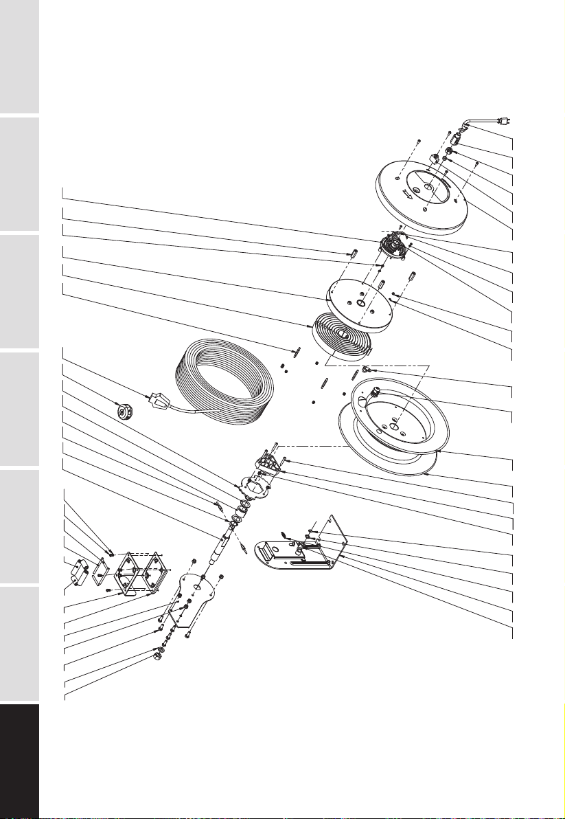
EXPLODED AND
PARTS LIST OPERATIONOTHERS INSTALLATIONMAINTENANCE
Wall Floor Ceiling