HCT HelioJET C-100 Owner's manual
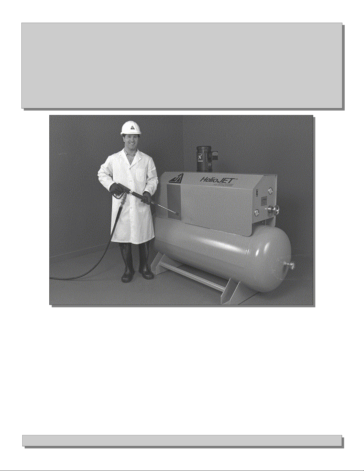
HelioJET™
Model
Central Cleaning C-100
HelioJET Cleaning Technologies • 57 North Street / Suite 120 LeRoy, NY 14482 • Tel 585-768-8710 Fax 585-768-9209
Installation
Operation
Maintenance
M-C100-02-01

Table of Contents
Important Safety Precautions 3
HowitWorks 4-5
Installation 6-10
Start-up 11-13
TroubleShooting 14-15
Preventative Maintenance 16-19
Major Components and Spare Parts 20-22
LimitedWarranty 23
2

Safety Precautions
SAFETY PRECAUTIONS:
Please be sure the following instructions are understood thoroughly BEFORE operating the system. Consult our representative in
your area or call the factory to resolve the items you do not understand.
This equipment can be used to generate:
1. A high pressure fluid that can penetrate the skin and cause severe internal injury.
2. A hot fluid which can severely burn the body.
3. A chemical solution ranging from mild to highly dangerous; protective equipment must be worn by
the operator.
Therefore:
1. NEVER exceed inlet pressure of 160 psig for either steam or water supply.
2. NEVER operate the system with a defective hose.
3. ALWAYS allow hose a minimum 9 inch bend radius.
4. ALWAYS check hose for kinks or abrasions that may develop into a rupture.
5. ALWAYS use hardware (valves, fittings, quick disconnects, etc.) which are rated for the
maximum discharge pressure at which you could be operating.
REMEMBER:
The HelioPAC is a powerful fluid pressure amplifier and condenser which can multiply the inlet pressure several times! For
example, with 150 psig of inlet water and 150 psig inlet steam, the discharge pressure could reach 600 psig at 212ºF and be laden
with dangerous chemicals. This system deserves respect!
Install in accordance with all applicable codes. Start-up/overflow shall be rigid, threaded pipe, firmly anchored directly to a drain
and away from personnel. Adequately support all equipment and plumbing.
OBSERVE ALL ADDITIONAL SAFETY PRECAUTIONS FOUND IN THIS MANUAL.
3
! !
The Patented How it works
HelioPAC™
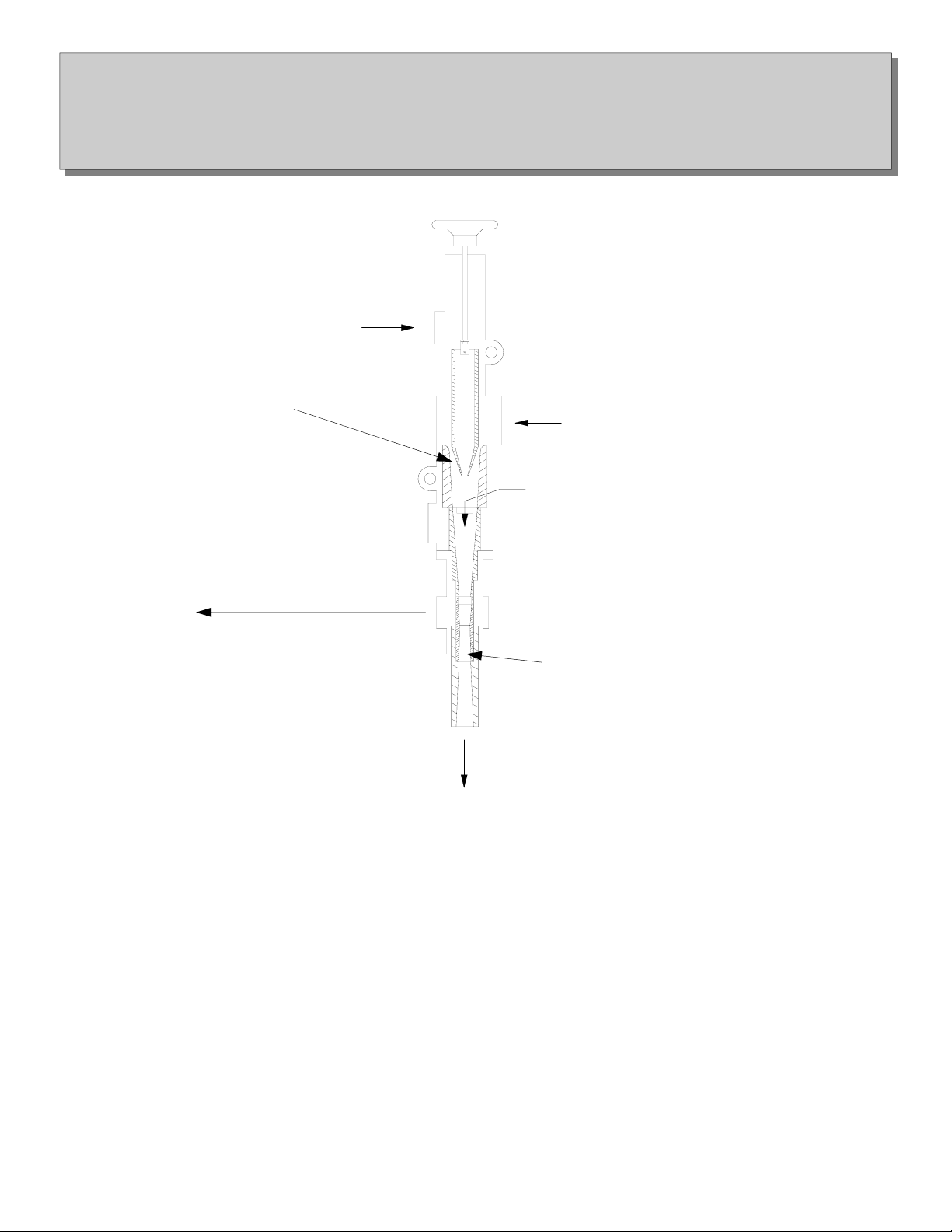
The Patented HelioPAC
An entering stream of cold water encounters a supersonic stream of steam molecules within the HelioPAC™.
As the steam molecules condense into the water stream, momentum and heat transfer takes place. This transfer causes a significant
increase in the temperature and velocity of the incoming water.
The HelioPAC converts this velocity to pressure, increasing the pressure of the incoming water up to 10 times.
4
Liquid
Vapor
Secondary Inlet
(Optional)
Start-up
Overflow
Discharge
High Velocity Stream
Water Supply
Steam Supply
Start-up/Overflow to Drain
High Velocity Hot Water
Supersonic Steam Flow
Velocity to Pressure Conversion Area
Discharge
Figure 1

The Central How it works
Cleaning System
The Central Cleaning System
Pressurized water is piped from the pressure reserve tank (1) to desired cleaning locations within the plant. As this water is used,
pressure within the reserve tank drops. An electrical pressure switch (2) senses this drop and energizes the automatic water valve (3)
and the stabilizer pump (4) which sends cold water through the water inlet line to supply the HelioPAC (7). The flowing water
closes the flow switch circuit (5) which energizes the air actuated steam valve (6) allowing steam to flow to the HelioPAC, where it
encounters the incoming water. The HelioPAC starts and fills the reserve tank to the desired pressure, as set by the pressure switch.
When the pre-set pressure is reached, the pressure switch opens and the system is in the stand-by mode, waiting to be used.
5
1
2
3
5 7
6
4
Figure 2

6
HelioJET™ Installation
C-100
6
Follow these instructions and refer to specific pages and figure illustrations as specified.
Your HelioJET Central Cleaning System will require the following utilities and connections for proper operation:
• Cold water supply
• Steam supply
• Compressed air
• Floor drain
• Electricity
• High pressure discharge piping and spray equipment
Location
It is recommended that you place your C-100 system away from production and other high traffic areas. A boiler or utility room is
ideal. Placing the system in the proper location will avoid problems that can arise from tampering, water damage, etc.
Water Supply
Use 2-1/2” cold water supply less than 80ºF. The supply connection is actually 2”, however it is best to use a
2-1/2” supply line. Water supply pressure must be stable. The supply line should be dedicated exclusively to the HelioJET and
piped directly from a larger main.
Install a manual shut off valve (sold separately) and be sure it is accessible from the HelioJET location. Always use a full port or
oversized valve in order to avoid a pressure drop.
If your plant has a water hardness problem, be sure that the HelioJET is supplied with soft water. This will prevent fouling in the
system.
Note:
To optimize performance, always avoid pressure drops in supply lines. Locate the HelioJET as close as possible to the water and
steam source, and never undersize piping. If the HelioJET must be located a considerable distance from supply mains, increase pipe
diameters feeding the unit. Avoid the use of restrictive devices in piping, such as regulators, etc.
Before actually connecting supply lines, thoroughly flush them to remove any debris that may plug orifices within the system and
impede start-up.
Steam Supply
The HelioJET C-100 requires a 2-1/2” dedicated steam supply line.
Install a 2-1/2” manually operated shut-off valve, and be sure it is accessible from the C-100 location.
Standard HelioJET systems are designed to operate on steam supply pressures of 75-150 psi. If your steam supply pressure is out-
side this range, contact the HelioJET Technical Service Department for assistance. HelioJET systems can often be modified in the
field to accommodate other supply conditions.
The C-100 will consume 75-100 lbs. of steam per minute depending on internal orifice configurations. This equates to a boiler re-
quirement of 155-210 horse power. Please be sure you have enough boiler capacity to operate the system.

HelioJET™ Schematic
C-100
1. Water Supply: 2” NPT (use 2-1/2” supply line) 8. Operating Pressure Gauge
2. Steam Supply: 2-1/2” NPT 9. Start-up Vacuum Gauge
3. Discharge Line to Plant: 2” NPT 10. Thermometer
4. Start-up/Overflow to Drain: 1-1/2” NPT 11. Handwheel Adjustment
5. Electrical Control Box 12. Power Switch
6. Steam Trap: 1/2” NPT 13. High-Low Pressure Switch
7. Pressure Reserve Tank (300 Gallon, A.S.M.E rated 600 psi MWP)
Figure 3
62”
74”
7
5
13 1 4 2
12
9
HelioPAC
11
8
3
10
7
6
52”
80”

Floor Drain
Pipe the start-up/overflow downward to a drain using no less than 1-1/2” or larger rigid pipe. See page 7, item 4.
During times of use, the HelioJET will discharge approximately one pint of hot water to drain each time it cycles on and off. Be sure
the drain you choose can accommodate 200°F.
Never submerge the start-up/overflow pipe into a floor drain or sump. Always leave a little space between the end of the pipe and
the waste water level in order to prevent syphoning.
Never route overflow piping overhead; doing so can impede start-up.
Caution: Be sure personnel are safe from overflow splash. In some cases thrust may develop in the start-up/overflow line
causing it to move. This can be dangerous. To prevent movement, be sure all piping is firmly anchored.
Caution: Never use a flexible hose on the start-up/overflow line. Always use hard pipe and be sure the selected drain can
handle hot water. Firmly anchor overflow piping. Never plug, undersize, or restrict overflow piping in any way. Never pipe
overflow anywhere near an occupied area.
Safety Relief
The C-100 is equipped with a 600 psi safety relief valve located at the rear of the pressure reserve tank (pg. 21, item 21). It should
be piped downward, with a 1” line firmly anchored and extended to a safe drainage location.
Electrical Supply
The standard C-100 system is wired to accept a 3 phase 460 volt supply. This can be modified to customer specification before
shipment. All internal control wiring and components, such as starter, overload, etc. are
included in the package.
High Pressure Discharge Piping
To supply pressurized hot water to spray gun stations or other cleaning equipment in your facility, connect high pressure piping to
the discharge ball valve (2”) located at the rear of the pressure reserve tank (pg. 7, item 3)
Use at least 2” discharge pipe for the riser and main feeding the plant. Do not use black steel pipe, stainless steel is recommended.
Be sure all piping is rated for at least 600 psi and 200°F.
Piping to Spray Drops
If your spray station will use 8 gallons per minute or less, use a 3/4” pipe from the main header to the cleaning location.
If your spray station will demand between 8-16 gallons per minute, use a 1” pipe from the main header to the cleaning location.
Use standard fluid hydraulic theory and always maintain a water velocity of less than 6 feet/second. Never undersize discharge
piping as it will cause an unnecessary pressure drop at the point of use. 2” ID pipe is usually adequate for most installation.
CAUTION: Be sure all pipe and fittings are rated for a least 600 psi and 200°F.
Spray Accessory Installation
Refer to page 10 figure 4 for guidance on spray accessory installation. It is very important that spray equipment such as hoses, spray
guns, foamers and injectors are not installed until after the initial calibration and startup procedure is complete. At this time, install
only discharge piping between the HelioJET System and shut off valves (page 10 items 1,2,5, and 6) located at the spray stations
(point of use). This will allow for flushing of the discharge piping during the initial calibration and startup procedure.
8
9
HelioJET™ Electrical C-
100 Schematic
4
26
8
35
71
Steam Solenoid
Water
Solenoid
Flow Switch
Main
Switch
Ground Pump
Motor
Fuse Block
A1
A2
96
L3
L2
L1
Transformer
Timer
H1 H4
X2 X1
Normally Open
Off Delay Relay
T1 T2T3
Alarm/Light
Condensate
Indicator
8
6
2
47
1
3
5
High Probe
Reference Probe
Ground
Tank if metallic may be used
instead of reference probe.
Solid State
Relay Module
9
10
11
Steam Probe
Relay
Motor
Starter
Overload
5
1
1
1
1
2
6
1A
1A
9
Push to Test
2B
1
9
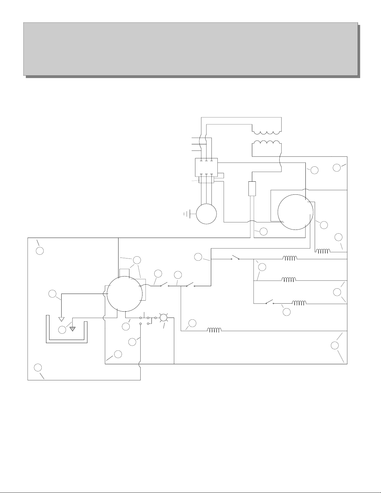
Electrical Schematic
C-100 Central System
460V 3 Phase
D00306
Pressure
Switch
3
4
Discharge Solenoid
Air Solenoid
Vacuum
Switch
7
8
9
9
3
9
Discharge Solenoid
(To Plant)

6
7
12
12
1
5
13 9
2
3
4
13
11
10
8
1. 3/4” Main Station Valve
2. 3/8” Sanitizer Valve
3. Liquid Injector
4. 3/4” Safety Coupling
5. Bypass Valve. Close for Liquid
Injector to Pick-up.
6. Foam Valve
7. CPS Hot Foamer
8. Air Supply Valve
9. Foaming Nozzle
10. G-7 Spray Gun (up to 8 GPM)
11. 1/2” Hose Swivel
12. 3/4” Quick Disconnect (Fem.)
13. 3/4” Quick Disconect (Male)
14. 3/4” Foam Hose
15. 1/2” Spray Hose
16. 3/4” X 1/2” Bushing
17. Detergent Pick-up Tube
Note: Items 12 and 13 are optional and serve to
make the spray gun and hose mobile.
17
16
14
15
G-7 Spray Gun Typical
Hot Foam, Sanitize Installation
and Rinse Station
10
Figure 4
3/4” or 1”

Start-up
Preparing for Initial Calibration and Start-up
After the HelioJET C-100 has been installed, complete the following steps before attempting to start the system.
Caution!! Be sure all shut off valves are closed at all spray stations out in the plant. See page 10 figure 4 items, 1,2,5, and 6.
Precharge Reserve Tank
Connect air hose line to the 1/4” tank air charge valve located at the rear of the reserve tank (see page 13 fig. 6).
Charge the reserve tank with air pressure (75-100 psi).
Close 1/4” tank charge valve, remove air hose, and connect it to the air actuated steam valve (see page 13 fig. 6). Charging the
tank is a one time procedure. It should not be necessary to repeat except for maintenance purposes.
Pump Rotation
Be sure the manual steam valve is closed and the manual water supply valve is open. Turn the power switch on and off quickly.
The pump shaft should turn in the direction of the arrow located on the pump housing.
Remove Condensate
Be sure all condensate from the steam line has been purged and that the steam trap is working properly.
Two Adjustments
There are two adjustments on your HelioJET C-100. You will make them during the initial calibration and start-up procedure in
the next section. Please refer to pages 7 and 13 to familiarize yourself with the location of the handwheel adjustment and the
high-low pressure switch. After you have located these two components, you may begin the calibration and start-up procedure.
Please do not arbitrarily make adjustments.
Initial Calibration and Start-up
Before attempting to start this system, be sure it has been installed in accordance with all previous instructions, and that the proper
procedures have been followed. If you have any questions, contact the HelioJET Technical Service Department at 1-800-444-
3546.
Please read all of the following steps before beginning, and be sure to follow them in proper order:
Step 1. Be sure the Handwheel adjustment is turned clockwise to fully bottomed position.
Step 2. Adjust pressure switch (upper dial) to 500 psi (see page 13, fig. 5).
Step 3. Open manually operated water and steam supply valves to system (be sure all condensate has been drained from the steam
supply line).
Step 4. Turn the HelioJET power switch on. Water will flow to drain from the start-up/overflow.
Step 5. Observe the start-up vacuum gauge, and begin quickly turning the Handwheel counter-clockwise. At some point the
gauge will suddenly read a vacuum. Continue to turn the Handwheel rapidly in the same direction. The vacuum reading will
decrease, continue until the vacuum reading is 8 inches. The Handwheel is now calibrated, do not continue to adjust it. Observe
the discharge pressure gauge. Pressure will build in the reserve tank and the start-up/overflow will cease to discharge water to the
drain until the system reaches its maximum pressure. At that time one of the following two things will occur:
A. The reading of 8” on the start-up vacuum gauge will go to 0 or higher, the system will continue to run, and water will again
flow to the start-up/overflow drain.
B. The system will shut down.
If A occurs, continue on to step 6. If B occurs, skip step 6 and proceed to step 7.
11

Step 6. Adjust the high-low pressure switch (upper dial) downward until the system shuts down.
Step 7. After system shuts down, reduce the pressure switch (upper dial) an additional 50 psi.
Step 8. Adjust pressure switch (lower dial) to obtain a 75 psi pressure differential.
Step 9. Before installing discharge hoses, spray guns, CPS Foamers, etc. it is very important that discharge lines be thoroughly
flushed. At this time, only shut off valves should be installed out at the cleaning drops (spray gun location). Be sure these valves
are closed before allowing hot water to be fed into the plant piping network.
Refer to page 10 figure 4, items 1,2,5, and 6.
Step 10. Open 2” discharge ball valve in order to allow pressurized hot water to fill the plant piping network. The HelioJET may
cycle on and off when you do this.
Step 11. Caution!! Hot Water Burn Hazard. Go to each cleaning drop and slowly open discharge valves in order to flush lines
and remove debris that has accumulated as a result of the piping installation. Depending on the lengths of piping involved, 30
seconds to 1 minuet of flush time is usually adequate.
Caution!! Be careful, you are dealing with extremely hot water that can easily burn the skin. Stand clear and open valve
slowly.
Step 12. After flushing lines, close discharge valves at the drops, and shut HelioJET System down (simply turn off power switch)
in order to install spray equipment such as guns, hoses, etc.
Step 13. After spray equipment is installed, follow the “Routine Start-up and Shut Down Procedure” below.
Routine Start-up and Shut Down Procedure
Steps 1-13 are for initial calibration and start-up only. Once the handwheel and pressure switch have been adjusted, lines have
been flushed, and spray equipment has been installed, it is only necessary to follow the routine start-up and shut down procedure
described below.
During times of clean-up, the HelioJET can be left on. It will cycle on and off as pressurized hot water is used for clean-up
purposes.
If the system is to be turned off until the next clean-up period, follow these routine start-up and shut down procedures:
Routine Start-up
1. Turn power switch on.
Routine Shut Down
1. Turn power switch off.
12

Data Shee
t
#B 107
InitialCalibration&Start-U
HelioJET™Central
CleaningSystem
Fig. 1
High-LowPressureSwitch
High Setting (Upper Dial)
Low Setting (Lower Dial)
Fi
2
ON
OFF
Start-Up
Vacuum Gauge
(Inches/Vacuum)
Air Actuated Steam Valve
Handwheel Adjustment
Discharge
Pressure
Gauge
Discharge
Thermometer TankAir Charge Valve
Steam In
ToSpray Stations
2" Discharge Ball Valve
System On/Off
Switch
Start-Up/Overflow
Initial Calibration & Start-up
High-low Pressure Switch
Figure 5
High Setting (upper dial)
Low Setting (lower dial)
C-100 System
Figure 6
Power Switch
Discharge
Pressure
Gauge
Discharge
Thermometer
Start-Up
Vacuum Gauge
Set at 8” vacuum
Start-Up/Overflow Drain
Air Actuated Steam Valve
Steam Supply
Handwheel Adjustment
Tank Air Charge Valve
To Spray Stations
2” Discharge Ball Valve
13

Problem
The system starts and runs fine, but does not deliver the discharge temperature anticipated.
Solution
Before start-up, the reserve tank is at ambient temperature. It takes a little time to rise to full temperature. For instance, after the
first cycle, the discharge thermometer may read 140-150°F and you are expecting 180°F. Use the system and allow it to cycle on
and off about 3-4 times, it should not take more than 10 minutes to come up to temperature. Keep in mind that discharge
temperature may vary with water supply temperature.
Problem
The HelioJET starts and develops pressure in the reserve tank, but suddenly begins to overflow water to the start-up/overflow drain
(a chattering sound may also accompany this).
Solution
Refer to steps 5-8 on page 11 and 12 of section titled “Initial Calibration and Start-up” and follow procedure.
Problem
When system power switch is turned to the on position, the system discharges water to the drain. The steam valve does not open and
the HelioJET will not start.
Solution
A. Do you have 80-120 psi air pressure supplying the air actuated steam valve?
B. Refer to page 21, item 7, for the location of the flow switch. The flow switch is a safety and timing component that controls the
opening of the air actuated steam valve. If the flow switch does not function properly it may prevent the opening of the steam valve.
Refer to page 16 (Flow Switch Maintenance) in the Preventative Maintenance section of this manual.
Problem
I turned the power switch off while the system was in the midst of a cycle (building pressure in the reserve tank). When I turned it
on again, it started to overflow and would not stop.
Solution
Reduce the pressure in the reserve tank below the lower dial setting on the pressure switch, and try again. It is important that reserve
tank pressure be reduced to the proper level in order for start-up to occur.
Be sure the handwheel is adjusted so that the start-up vacuum gauge reads 8” when the system is running.
Trouble Shooting
Problem
Spray Gun does not deliver enough pressure.
Solution
A. Remove nozzle at tip of spray gun, inspect for plugging or damage.
B. Are you using well maintained and appropriate spray nozzles? Contact HelioJET for recommendations on nozzle sizing.
C. Are you using a HelioJET recommended spray gun? Most spray guns available on the market are designed for low flow
applications, specific to the car wash industry. These spray guns are often not appropriate for in-plant applications, as they cause
considerable flow restriction which reduces pressure and impingement at the surface being cleaned. Contact HelioJET Cleaning
Technologies for spray gun recommendations.
14

D. Is your discharge piping undersized? See Installation section.
E. Is it possible that your lines have developed some mineral or other type of build-up that may be creating a flow restriction?
Contact HelioJET if you are unable to resolve this problem.
Problem
When the Handwheel is adjusted upward, (counter-clockwise) the start-up vacuum gauge never reads a vacuum. Water
continuously discharges from the overflow no matter how high it is adjusted.
Solution
A. Has all condensate been removed from the steam supply line? The HelioJET must be supplied with dry steam to operate.
B. Is water supply over 80°F? Standard equipment must not be supplied with water over 80°F.
C. Is start-up/overflow piping routed overhead? It should be at a declining level to the drain for proper start-up.
D. Is start-up/overflow line at least 1-1/2” in diameter and completely free from obstructions? Never plug, restrict, or valve off the
overflow.
E. Inspect the internal condition of the overflow check valve. If check valve seat is lodged or damaged it can obstruct the overflow
line. This may prevent start-up, disturb the vacuum reading, or cause the unit to continuously overflow water and/or steam vapor.
See page 21, item 12.
F. Is steam pressure at least 75 psi? Perhaps it is at the boiler but there are line losses making it less at the HelioJET. In most cases,
HelioJET systems can be field modified to operate on steam pressure less than 75 psi. For further assistance, contact the HelioJET
Technical Service Department at 1-800-444-3546.
Problem
System will not Start and red condensation light stays lit.
Solution
Be sure that the steam trap is not plugged, and that condensation can exit properly. Allow sufficient time for steam
condensation to drain from the steam supply line. To speed up the process you may use the blow off valve located on the steam
line’s Y strainer. This will allow you to remove some of the excess condensation faster. If this is a problem that prevents normal
operation during routine use you may have to reconfigure your steam supply, or better insulate the supply line.
15

Preventative Maintenance
After the HelioJET is installed and adjusted properly, it is recommended that a monthly inspection be performed to verify that the
pressure switch and handwheel settings have not been changed. If necessary, reset according to the initial calibration and start-up
section of this manual.
Flow Switch Maintenance
For location of the flow switch see page 21, item 7. The flow switch acts as a safety and timing mechanism for the air actuated
steam valve. When water supply to the HelioJET is adequate, the flowing water lifts the metering disc which raises the magnet. The
magnet completes the circuit allowing power to the steam valve. If the flow switch does not function properly it will affect steam
valve operation. Inspect the magnet and other components to be sure they are intact.
Body Housing
Bonnet Assembly
Flow Switch
5
1
2
3
4
Bonnet Nut
Component Description Part Number
Flow Switch Complete FS-2-35-01
Bonnet Assembly Complete FSB-2-35
1.O-ring 611035
2. Spring SPR-02
3.Magnet MAG-01
4.MeteringDisc MD-2-35-01
5.SnapRing SR-01
6.SnapRing SR-02
16
6

Steam Valve
Check condition of steam valve seat. Does steam leak through the overflow drain, even when the C-100 System is not being used?
If so, replace the steam valve seat.
Steam Valve Solenoid
Check condition of steam valve solenoid. Does air continuously leak from the solenoid, even when the system is not running? If
so, replace the solenoid.
Air Actuated Steam Valve
1
2
3
4
Valve Body
Actuator Head
Assembly
Steam out
Steam in
SteamValve Part
Components Number
Complete Valve Assembly S-AVP-2-05
Actuator Head Assembly ACT-13
PilotAssembly S-PV-01
1.ConduitPlug CP-01
2.Solenoid SOL-01
3.Adapter ADA-01
4.ValveSeat 17 RK-AVP-2-02
Pilot Assembly

Cycle Time
Cycle time refers to the time it takes for the HelioJET to fill the pressure reserve tank once the system is activated. A normal cycle
(time to fill the reserve tank) is approximately 10-20 seconds, when there is no hot water being used. The cycle time will increase
proportionally as the demand for hot water increases. If cycle time is less than 5 seconds, inspect the following:
A. Pressure switch differential setting should always be at least 75 psi. If it is less, HelioJET cycle time will decrease proportionally.
B. The air intake nozzle and air intake check valve must be clean in order for the HelioJET to properly draw in air from the
atmosphere and maintain the proper air level in the reserve tank. To inspect the air intake for free air flow, first be sure that the start-
up vacuum gauge is reading a 8 vacuum when the system is running. While the HelioJET is filling the reserve tank, place your finger
over the air intake nozzle. If you feel a vacuum, the air intake is working properly. For location of the air intake, see page 21, item
27.
C. If for any reason the pressure reserve tank loses its air, it will be evident as the HelioJET will cycle on and off rapidly.
To verify whether or not the reserve tank has lost its charge, first turn the C-100 power switch off. Second, close the manually
operated water and steam supply valves to the system. Finally, begin draining the reserve tank by opening a spray gun or other outlet
in the discharge piping. Allow the pressure in the reserve tank to drop until air begins to discharge from the spray gun or outlet.
When air discharge occurs, observe the pressure gauge on the HelioJET. It should read the same pressure as the original charge
(most likely 75-120 psi). If it is less, you may have lost some of the charge. If no air discharges from the gun at all, the air cushion
has been depleted and it must be replenished.
B. Excessive noise can also be caused by a faulty overflow check valve. If the overflow check valve does not seat properly it can
actually cause excessive air intake through the start-up/overflow line. This can result in increased noise level. If this occurs, the
overflow check valve must be disassembled, cleaned, and lubricated. In some cases, the check valve will have to be replaced or
rebuilt (see pg. 21, item 12.
Start-up Vacuum Reading
Is the start-up vacuum gauge working consistently when the HelioJET is running? If not, inspect the condition of the overflow
check valve (pg. 21, item 12). If the check valve does not seat properly it will allow an excess amount of air to enter the system.
This can disrupt the reading on the vacuum gauge (pg. 21, item 3). If the check valve proves to be in good working order, replace
the gauge.
Noise Level
Is the HelioJET system generating a high level of noise? Remember, normal noise level is 94 DB, but can be as high as 100. If the
noise level is higher, it may indicate a reduction of air intake through the air intake nozzle (see pg. 21, item 16).
Air intake is by vacuum. As the HelioJET operates, air is drawn into the system via the air intake nozzle. The air intake serves to
maintain an air charge in the pressure reserve tank and to reduce the noise level of the system during operation. A reduction in air
intake is usually the cause for increased operating noise. Air intake reduction is most commonly caused by the following:
A. Sticky check valve: If the air intake check valve does not open properly, the system will not entrain air. This will result in
increased noise level. To correct this, the check valve must be disassembled, cleaned, and lubricated. In some cases it may be
necessary to replace or rebuild it. (see pg. 21, item 27).
18

How to Recharge the Reserve Tank
If the reserve tank air cushion is lost, it will be necessary to replenish it. To do this, first, turn the HelioJET power switch off.
Second, close the water and steam supply valves that supply the C-100. Fourth, be sure there is no pressure in the reserve tank, open
air supply valve to relieve pressure if necessary (see page 21, item 20).
Caution: Water in reserve tank may be hot enough to cause severe burns! After you have completed the above steps, open
drain valve or plug at the bottom/center of the reserve tank and allow all the water to drain out. After water has been drained, close
drain opening.
To recharge the reserve tank, follow the standard procedure as outlined in the section titled “Initial Calibration and Start-up”. After
the system is operating, allow enough time for all air to be purged from the discharge lines.
Possible Reasons for Losing the Air Charge:
A. Improper Handwheel Adjustment
Improper handwheel adjustment can cause a gradual loss of the air charge. Is there a vacuum reading of less than 5” on the vacuum
gauge when the system is in operation? If so, the air cushion in the reserve tank may become depleted. A reduction in air intake as a
result of low vacuum is usually accompanied by an increase in noise.
B. Plugged Air Intake
The air nozzle and air check valve must be clean and open in order for the HelioJET to properly draw in air from the atmosphere.
To check whether or not the air intake is clean and open for free air flow, be sure the start-up vacuum gauge reads a 8” vacuum when
the system is running. While the HelioJET is running, place your finger over the air nozzle. If you feel a vacuum, the air intake is
working properly. Another indication that the air intake is working properly is that there will be an increase in system noise level
when you cover the air nozzle. For location of the air intake see page 21, item 16.
C. Open Discharge Valve
The 2” discharge ball valve to the plant should be closed when the system is not in use. If it is not closed, the tank may be drained
accidentally and the air cushion lost.
D. Leaks
Check for leaks in the system that may have caused the loss of air to occur.
E. Tank Check Valves
The tank check valves may need repair or replacement if, when charging the tank, it does not develop an air cushion, or if you hear
air escaping through the start-up/overflow drain (pg. 21, items 18 and 19).
For service assistance, call the HelioJET Technical Service Department at 1-800-444-3546. In order to help us serve you better,
please have your equipment serial number ready for our technician.
19
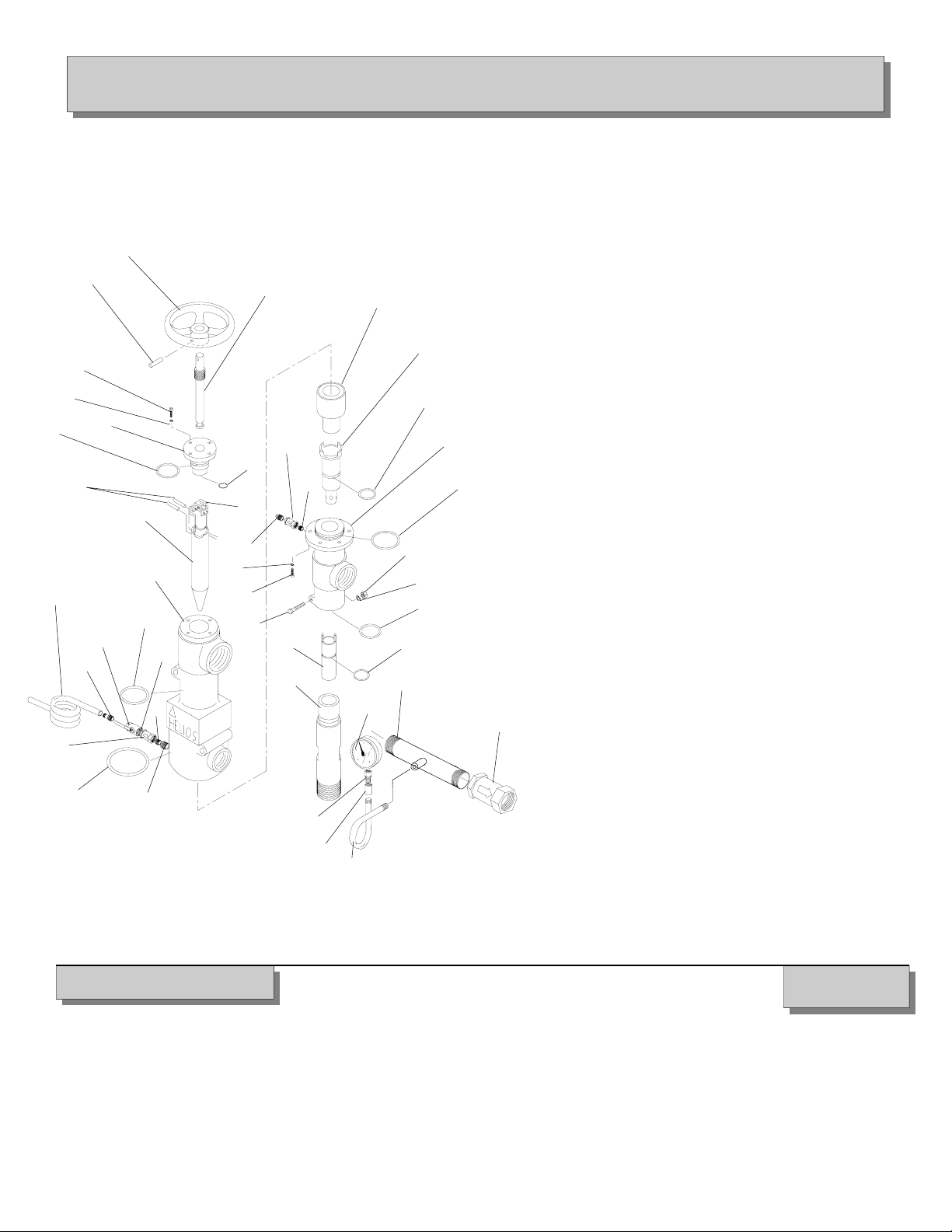
PAC 100
HelioPAC™ Maintenance
Item # Component (Part Number)
1. Handwheel 2000189-(625)
2. Dowel Pin (Handwheel) 615008
3. Waterjet Shaft 100172
4. Socket Head Screw (4) 612023
5. Lock washer (4) 613001
6. Plug 200373
7. O-Ring 611033
8. O-Ring 611037
9. Water Jet Bracket 100171
10. Dowel Pins (Jet) 615021
11. Waterjet 200429-(XXX)
12. Body Casting 400032 13.
O-Ring 611032
14. O-Ring 611010
15. Mixing Chamber 200358
16. Amplifier 200357
17. O-Ring (Amplifier) 611019
18. Manifold 300057
19. Lock washer (6) 613001
20. Socket Head Screw (6) 612023
21. O-Ring 611011
22. Nut (Shoulder) 614011
23. Lock Washer (Shoulder) 613008
24. Bolt (Shoulder) 612029
25. O-Ring 611025
26. Insert 200428-(XXX)
27. O-Ring 611006
28. Diffuser 200359
Detergent Inlet Assembly (complete)
29. Vinyl Tubing 632055
30. Hose Barb 632092
31. Ball Valve BV-1/2-02
32. Nipple 616107
33. Check Valve CV-1/2-05
34. Nipple 616107
35. Bushing 625035
Start-up/overflow Assembly (complete)
36. Nozzle 100054-0025
37. Check Valve CV-1/4-03
38. Nipple 616054
39. Nipple 616227
40. Vacuum Gauge 620030
41. Check Valve CV-1-1/2-05
42. Pig Tail 630004
43. Coupling 622004
44. Snubber 620032
PAC™ 100 Major Components
After a long period of operation, wear will begin to occur at the smallest orifice diameters located in the Amplifier (#16) and Insert
(#26). These two components will eventually need replacement. Indications of wear are a decrease in output pressure, and constant
overflow, even after attempts have been made to adjust the handwheel. To confirm that wear has actually occurred, please consult
our Technical Service Department before replacing these components. Dial 1-800-444-3546.
20
1
2 3
4
5
6
7
8
9
10
11
12
13
32
31
30
29
33
14
34
35
15
16
17
18
21
37
36
38
19
20
24
22
23
25
26 27
28 39
41
40
42
43
44
Table of contents
Other HCT Cleaning Equipment manuals


Popular Cleaning Equipment manuals by other brands


Prochem
Prochem PERFORMER operating instructions

Alfalaval
Alfalaval SaniMagnum instruction manual

Prochem
Prochem Micro-Mist M500 Safety, operation & maintenance instructions

Good Way
Good Way 93-ACC-BRUSHLESS Operating and maintenance instructions

Ryobi
Ryobi RY3112WB Operator's manual

Pro-Ject Audio Systems
Pro-Ject Audio Systems VC-S3 Instructions for use


