3/15
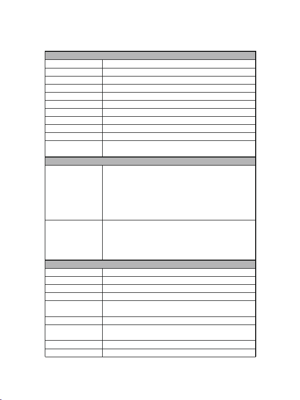
4. Specifications
Technical
HDMI Compliance HDMI 1.4b
HDCP Compliance HDCP 1.4
Video Bandwidth 4.95 Gbps
Video Resolutions 640x480p@60Hz ~ 1920x1080p@60Hz
Output Video Type H.264/MPEG-4 AVC
Encoding Data Rate Up to 30Mbps, configurable
Color Space RGB, YCbCr 4:4:4, YCbCr 4:2:2
Color Depth 8-bit
HDMI Audio Formats LPCM 2CH, 48KHz
L/R Audio Formats Analog Stereo 2CH
ESD Protection Human body model — ±8kV (air-gap discharge) & ±4kV (contact
discharge)
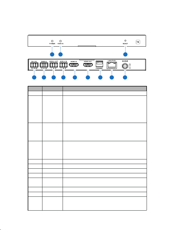
Connections
Encoder
Inputs: 1x HDMI Type A [19-pin female]
1x L/R Audio In [3.81mm Phoenix connector]
1x RS-232 [3.81mm Phoenix connector]
Outputs: 1x LAN [RJ45 connector]
1x HDMI Type A [19-pin female]
1x L/R Audio Out [3.81mm Phoenix connector]
1x Debug [3.81mm Phoenix connector]
Decoder
Inputs: 1x LAN [RJ45 connector]
Outputs: 1x HDMI Type A [19-pin female]
1x L/R Audio Out [3.81mm Phoenix connector]
1x RS-232 [3.81mm Phoenix connector]
1x Debug [3.81mm Phoenix connector]
Mechanical
Housing Metal Enclosure
Color Black
Dimensions 200mm [W] x 103mm [D] x 20mm [H]
Weight Encoder: 530g Decoder: 526g
Power Supply Input: AC100 - 240V 50/60Hz
Output: DC 12V/1A (US/EU standards, CE/FCC/UL certified)
Power Consumption Encoder: 5.7W (Max) Decoder: 5.6W (Max)
Operation
Temperature 32 - 104°F / 0 - 40°C
Storage temperature -4 - 140°F / -20 - 60°C
Relative Humidity 20 - 90% RH (no condensation)