Healthcraft SuperPole FRS Series User manual

HealthCraft Products Inc., Toll Free 888-619-9992.
2790 Fenton Road, Ottawa, Ontario, Canada, K1T 3T7.
DC109 Rev B Page 1 of 4
Specifications subject to change without notice.
www.healthcraftproducts.com
WARNING - PATIENT ENTRAPMENT!
The potential risk of entrapment (limb, neck, head, torso)
between the rail and adjacent item (i.e. bed) can be
reduced or avoided by the following strategies:
1. Consider situations that could change with time or
usage such as mattress compression, patient movement.
2. Realize that this product is not intended as a physical
constraint or barrier to exiting the bed.
GETTING STARTED
We strongly recommend that you give thought as to the
optimal location of your SuperPole™ FRS before
installation. The following questions may help you to
decide upon a location:
a. What motions will you be going through? (pulling up to
standing, lowering to sitting, transferring from chair to
toilet, etc.)
b. What is your strongest side/hand?
c. What is your complete transfer path? Will the location
allow for full support over most of your path of motion?
d. Will the pole be far enough away to allow you
to stand comfortably?
SUPERPOLE FRS™ PLACEMENT
NOTE: If using the SuperBar Add On Kit (SPB-AK),
please refer to the instructions for the SuperBar to
help determine placement of SuperPole™ FRS.
BEDROOM
Locate unit adjacent to hip/belt line and as close to bed
as possible while allowing clearance for bed coverings.
TOILET and / or BATHTUB
Toilet - suggested to locate floor receptacle between three
to ten inches forward of the knees and two to six inches to
side of knees when seated such as position C or D.
Bathtub - locate floor receptacle close to outer edge of
tub, approximately half way along its length such as
position D or E.
Installation Instructions: FRS-PWR, FRS-P, FRS-FR
B
ACD
E
SuperPole™FRS
(Floor Receptacle System)
THANK YOU...
Thank you for purchasing the SuperPole™ FRS. We are
confident that you will find the unique design and
durable construction of this product to be of great
assistance in your daily routine.
To fully enjoy your SuperPole™ FRS, please take a few
moments to read these instructions. You should store
these instructions in a safe place for future reference.
SAFETY CONSIDERATIONS
CAUTION: It is your responsibility to see that your
SuperPole™ FRS is properly assembled, installed, and
cared for. Failure to follow instructions in this manual
could result in serious injury.
SUPERPOLE FRS™ INSTALLATION /
MAINTENANCE
The SuperPole™ FRS should only be installed in
concrete slab type floors of structurally sound design. We
recommend that you have your SuperPole™ FRS
installed by a qualified contractor who should pay
attention to location of any in-floor structures or conduits.
The locking pins on the bottom of the SuperPole™ FRS
should be inspected regularly for damage. The floor
receptacles should be inspected regularly. Maximum
suggested user weight of 450 lbs/205kg.
WARRANTY
All HealthCraft™ Products are covered by a one year
limited warranty with the exception of hand grips which are
subject to normal wear. Buyer hereby indemnifies, agrees
to hold harmless and defend HealthCraft™ Products Inc.
from and against any and all liabilities, claims, (founded and
unfounded), losses, damages, costs and expenses
(including without limitation consequential damages and
reasonable professional fees) resulting from buyers
specification, application, or improper use of goods
described hereon; buyers omission or neglect.
HealthCraft™ Products Inc. does not assume any liability
for damage resulting from services performed by others or
faulty installation, misuse or misapplication of goods sold by
HealthCraft™ Products Inc.
HealthCraft™ Produts Inc. shall not be liable for prospective
profits or special, indirect, or consequential damages, or for
the cost of any corrective work done without HealthCraft™
Products Inc. prior approval. HealthCraft™ Products Inc.
total liability hereunder shall in no event exceed the
purchase price of the goods specified hereon.

Receptacle top surface
flush with floor.
HealthCraft Products Inc., Toll Free 888-619-9992.
2790 Fenton Road, Ottawa, Ontario, Canada, K1T 3T7.
DC109 Rev B Page 2 of 4
Specifications subject to change without notice.
FLOOR RECEPTACLE INSTALLATION
Read these instructions in their entirety prior to
commencing installation or use of the SuperPole™ FRS .
1. Using suggestions on page 1, determine a proposed
location for installation of the floor receptacle(s).
2. Check that the concrete floor is in good condition, and
that the depth of the slab is at least six inches prior to
drilling. IMPORTANT - Determine if there are any
conduits, wires, pipes or such within the floor to be
avoided during drilling, or a potential for the bottom of the
hole to fall through.
3. Select a locally available anchoring cement or
embedment grout to be used for the installation. It should
have a hardened bond and pullout strength of at least
2000 psi, compatibility with your floor cleaning chemicals,
and a pourable semi-liquid like consistency. (Suggestions
for this grout include HILTI HIT-HY150, from HILTI or
Anchorite Embedment Grout from C.C. Chemicals
Canada). Your selected grout should be confirmed to be
in accordance with any local codes in your area for safety,
disposal, and germ prevention.
4. Prepare to drill the hole for the receptacle. It is
recommended to create the hole with a 2" to 2-1/4"
diameter diamond type coring hole saw. The two inch size
results in the cleanest appearance of the hole with a
minimal appearance of grout around the receptacle, but
requires a flowable grout to fill into the small area around
the receptacle.
5. Referring to Figures 1, 2 & 3, the hole should be drilled
to 4-1/4" to 4-1/2" deep, and aligned as true vertical.
Follow the grout manufacturers’ guidelines for hole
preparation such as cleaning and roughening the hole
prior to using grout.
6. Referring to Figure 2, prior to mixing the grout, make a
test and lower the receptacle into the hole. Test that the
top of the receptacle does not sit above floor level. You
may choose to use thin metal pieces such as large
washers to place under the receptacle to shim it such that
the top of the receptacle is flush with the floor surface.
7. Once the hole and receptacle have been prepared for
installation, prepare the grout following manufacturer’s
directions. Referring to Figure 3, place/pour an amount of
the grout in the bottom of the drilled hole. You may also
apply some of the grout onto the sides of the receptacle to
pre-coat it for better adhesion.
Figure 3: Clean Hole & Add Anchoring Grout.
Figure 1: Locate & Drill Hole for Receptacle.
Figure 2: Test Hole Diameter and Depth.
Spacer Shims (if needed).
Qualified anchoring cement
or embedment grout.
Starting amount of anchoring
cement or embedment grout.
Approx. Depth
3"(2"Hole)
2"(2-1/4"Hole)
FRS Floor Receptacle.
Spacer Shims (if needed) as appropriate to bring
top surface of receptacle flush with floor surface.
2" to 2-1/4"
Concrete Floor /
SubFloor.
Correctly located
hole for receptacle.
Concrete Hole Saw
(Use 2" dia. for
cleanest appearance).
• Check for in-floor items such as conduit & pipes.
• Check for dangers below hole, such as wires,
fall through potential.
Hole Depth
4-1/4" to
4-1/2"
6" MIN
Floor
Depth
Clean & prepare hole
per grout manufacturer
instructions.

HealthCraft Products Inc., Toll Free 888-619-9992.
2790 Fenton Road, Ottawa, Ontario, Canada, K1T 3T7.
DC109 Rev B Page 3 of 4
Specifications subject to change without notice.
Figure 6: Cap Receptacle & Finish Top Grout.
Figure 4: Insert Receptacle into Grout.
Figure 5: Confirm Vertical & Let Grout Harden.
Leave top 1/2"
without grout
to allow for
finishing grout.
Take care not to let
grout overflow down
into receptacle.
Push down and
twist to ensure
good bonding.
Receptacle top surface
flush with floor.
Receptacle top surface
flush with floor.
Confirm pole with
bubble level.
Use FRS Pole to hold
receptacle vertical.
Allow grout to harden
while receptacle is held
exactly vertical.
Add grout around
top of receptacle
and smooth out
to finish with floor.
Once initial grout has
hardened, install cap
to seal receptacle.
FLOOR RECEPTACLE INSTALLATION (con't)
8. Next, referring to Figure 4, remove the cap of the
receptacle (as shown on page 2) and place a crumpled
rag/towel inside the receptacle to guard against any
grout entering the receptacle. Next, twist and force the
receptacle down into the grout until the top of it is
exactly flush with the floor surface. If the grout does not
rise up around the outside of the receptacle to within
approx. 1/2" of the top of the receptacle, remove the
receptacle, add more grout, and repeat. If the grout
overflows prior to the receptacle being fully lowered,
remove the receptacle and take out an amount of the
grout and reinstall the receptacle. Referring to Figure 5,
once the level of the grout has been finalized at 1/2"
below the floor surface, ensure that the receptacle is
exactly vertical. This may be accomplished by inserting
the FRS pole as a guideline, and correcting with the
guidance of a bubble level.
9. IMPORTANT - During installation take great care to
prevent the liquid grout getting down into the inside of
the receptacle. This can foul up the thread and pin holes
at the bottom of the receptacle. When sinking the
receptacle into the grout, keep the receptacle covered
or use a cloth rag inside the receptacle . Should any
grout enter the receptacle, immediately remove the
receptacle, and clean it out to prevent it from hardening.
10. Referring to Figure 6, after the initial grout has
hardened, add more grout around the top of the
receptacle and smooth it to be flush with the floor. Wait
the recommended time for hardening of the grout prior
to use.

HealthCraft Products Inc., Toll Free 888-619-9992.
2790 Fenton Road, Ottawa, Ontario, Canada, K1T 3T7.
DC109 Rev B Page 4 of 4
Specifications subject to change without notice.
FRS Pole used
to remove floor
receptacle
FRS Pole
installed into floor
receptacle
3
STEPS A&B
STEP C
1
4
7
STEPS A,B,C (Reverse steps
to remove pole from socket)
Line up drive pins with
drive holes in cap by eye.
Engage drive pins into
drive holes, and twist
pole (approx 6 turns) to
release cap.
Remove cap from floor
receptacle.
GENTLY lower pole into
floor receptacle
Rotate pole until it drops
down and stops rotating.
Rotate top knob to lock
pole into receptacle.
Remove rubber cover
from knob on top of pole.
Insert floor receptacle
cap into knob for storage.
Replace rubber cover
onto knob.
C. STORE RECEPTACLE CAP.
A. REMOVE FLOOR RECEPTACLE CAP.
B. INSERT & SECURE FRS POLE INTO FLOOR RECEPTACLE.
FRS POLE INSTALLATION
CAUTION
Inspect drive pins on bottom of
pole.
CAUTION - Rubber
sealing ring should sit tight
against the top edge of the
floor receptacle.
CAUTION - Rotate
top knob until bottom
surface is tight against top
edge of pole.
DAMAGED
CROOKED
MISSING
CORRECT
2
5
6
8 9 10
D=0" D=0"
This manual suits for next models
3
Other Healthcraft Mobility Aid manuals
Healthcraft
Healthcraft Advantage-Rail series User manual
Healthcraft
Healthcraft Advantage Rail AR-T User manual
Healthcraft
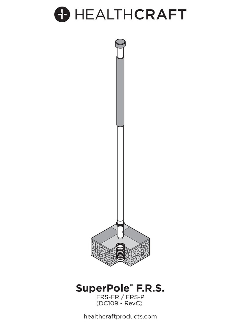
Healthcraft SuperPole F.R.S. Series User manual
Healthcraft
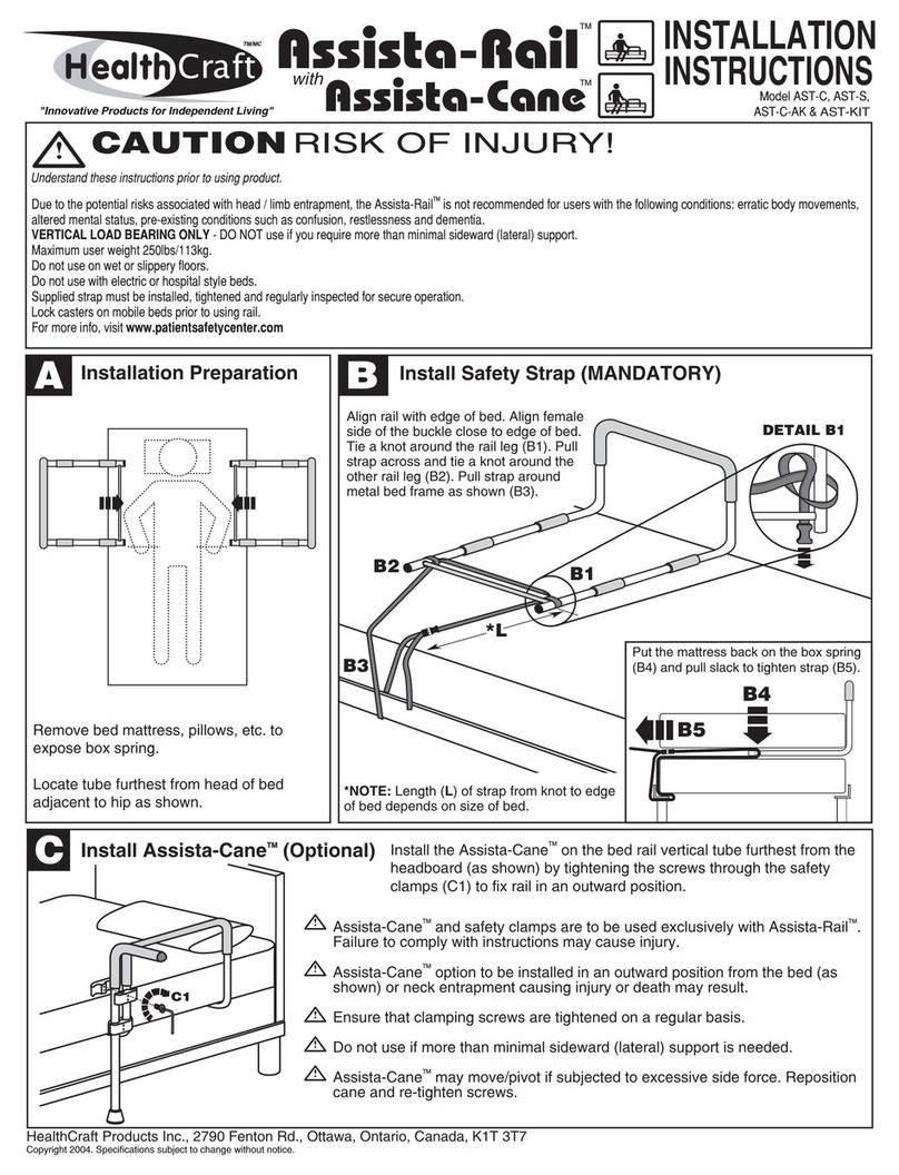
Healthcraft Assista-Rail Series User manual

Healthcraft
Healthcraft Advantage-Rail AR-PT User manual
Healthcraft
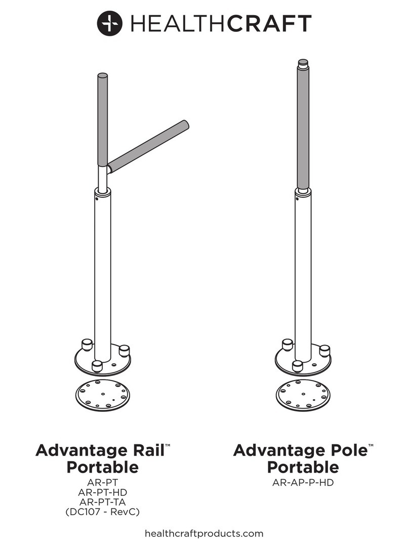
Healthcraft Advantage Rail Portable AR-PT User manual
Healthcraft
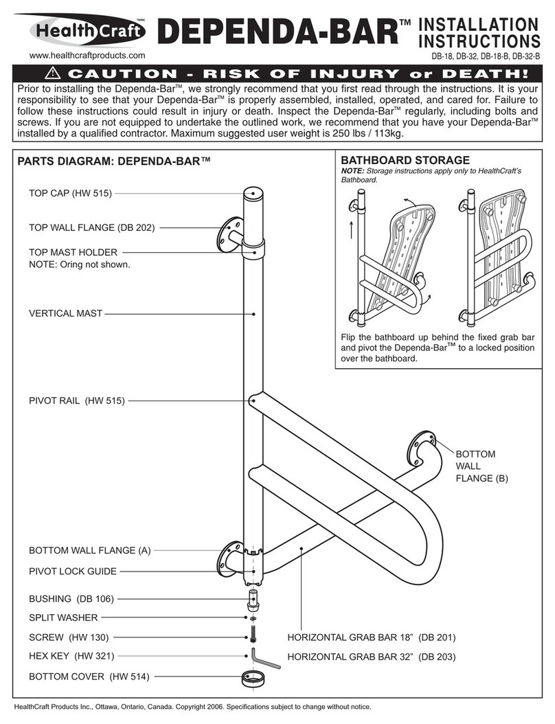
Healthcraft Dependa-Bar DB-18 User manual


