Healthstream FAN BIKE User manual

0
FAN BIKE
Owner’s Manual
Assembly
Usage
Parts
CAUTION: Weight on this product should not exceed 113 kgs.
CAUTION: Exercise of a strenuous nature, as is customarily done on this equipment, should not be
undertaken without first consulting a physician. No specific health claims are made or implied as they
relate to the equipment. Measurements made by the equipment are believed to be accurate, but only
the measurements of your physician should be relied upon.
IMPORTANT: Read all instructions carefully before using this product. Retain this owner’s manual for
future reference.

1
2 ■ Safety Precautions
3-4 ■ Pre-assembly Check List /
Hardware Packing List
5-11 ■ Assembly Instruction
12 ■
Computer Instruction
13 ■ Exploded Diagram
14-16 ■ C Parts List
17 ■ Trouble Shooting /Maintenance
18-20 ■ Training Guidelines
21-22 ■ Exercise Routines
Table of Contents

2
SAFETY PRECAUTIONS
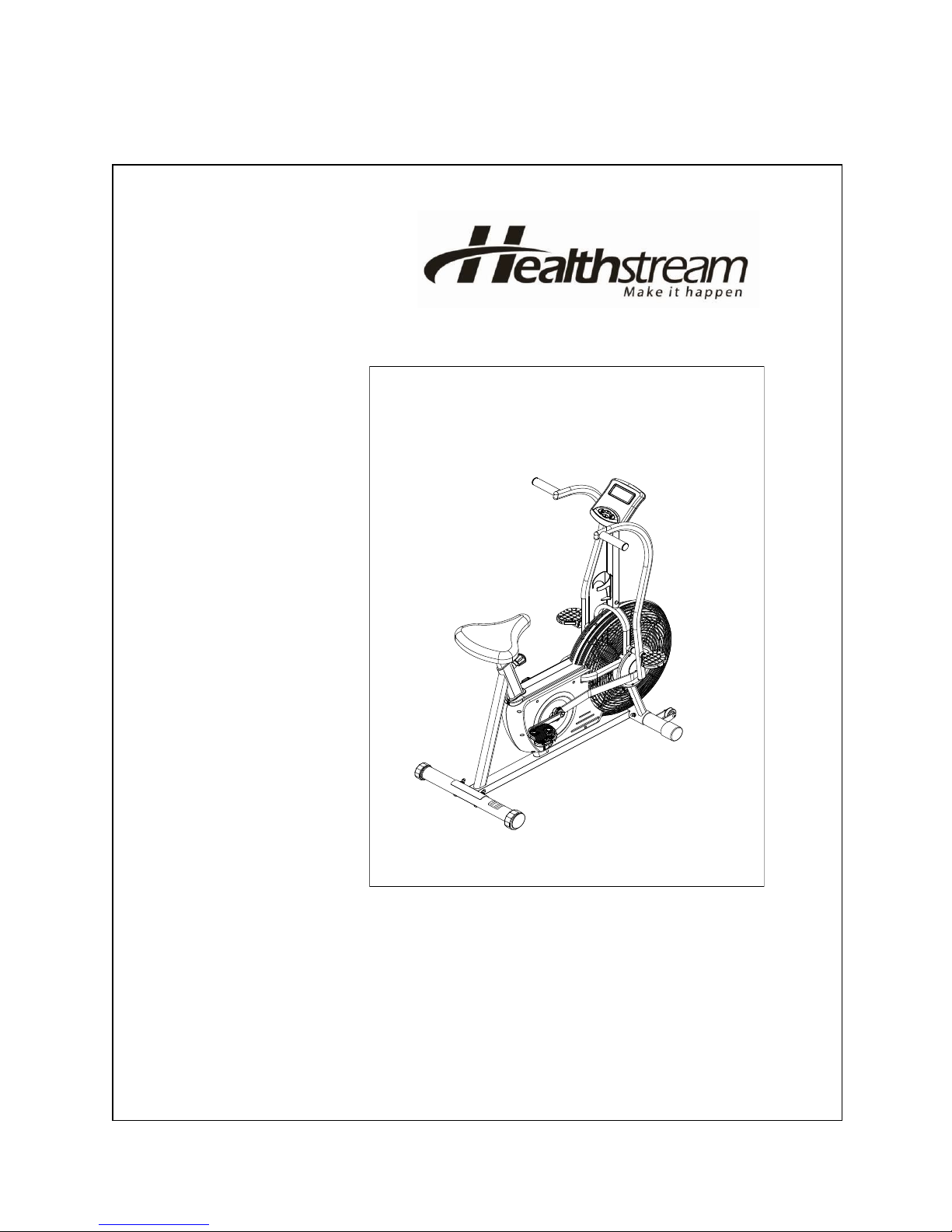
Thank you for purchasing our product. Even though we go to great efforts to ensure the quality of
each product we produce, occasional errors and /or omissions do occur. In any event should you
find this product to have either a defective or a missing part please contact us for a replacement.
This product has been designed for home use only. Product liability and guarantee conditions will
not be applicable to products being subjected to professional use or products being used in a gym
center.
This exercise equipment was designed and built for optimum safety. However, certain precautions
apply whenever you operate a piece of exercise equipment. Be sure to read the entire manual
before assembly and operation of this machine. Also, please note the following safety precautions:
1. Read this OWNER’S OPERATING MANUAL and all accompanying literature and follow it
carefully before using your upright cycle.
2. If dizziness, nausea, chest pains, or any other abnormal symptoms are experienced while
using this equipment, STOP the workout at once. CONSULT A PHYSICIAN MMEDIATELY.
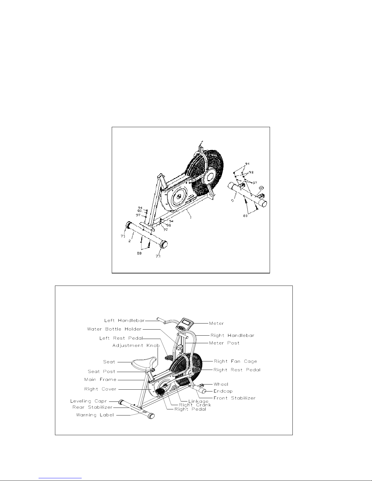
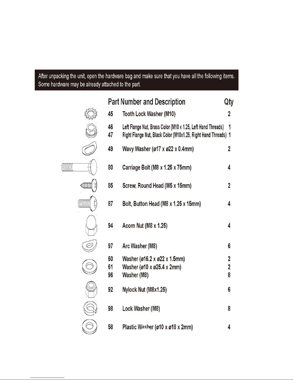
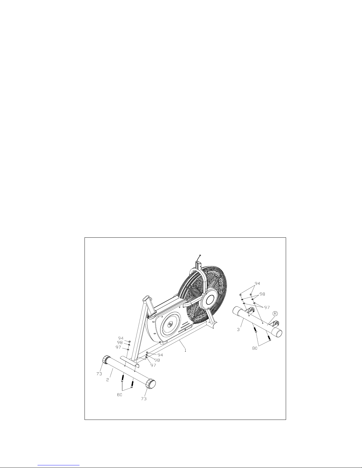
3. Inspect your exercise equipment prior to exercising to ensure that all nuts and bolts are fully
tightened before each use.
4. The upright cycle must be regularly checked for signs of wear and damage. Any part
found defective must be replaced with a new part from the manufacturer.
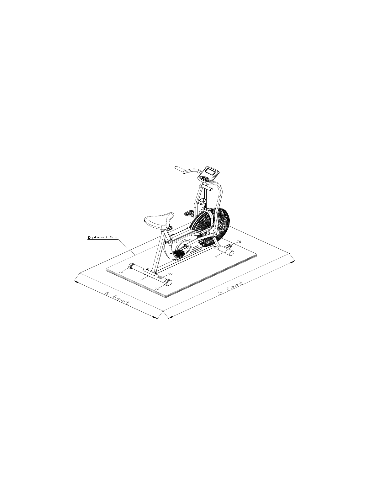
5. Fitness equipment must always be installed on a flat surface, It is recommended to use an
equipment mat to prevent the unit from moving while it is being used, which could possibly
scratch or damage the surface of your floor.
6. No changes must be made which might compromise the safety of the equipment.
7. It is recommended to have a minimum of 2’ safe clearance around the exercise equipment
while in use.
8. Keep children and pets away from this equipment at all times while exercising.
9. Warm up 5 to 10 minutes before each workout and cool down 5 to 10 minutes afterward. This
allows your heart rate to gradually increase and decrease and will help prevent you from
straining muscles.
10. Never hold your breath while exercising. Breathing should remain at a normal rate in
conjunction with the level of exercise being performed
11. Always wear suitable clothing and footwear while exercising. Do not wear loose fitting clothing
that could become entangled with the moving parts of your upright cycle.
12. Care must be taken when lifting or moving the equipment, so as not to injure your back.
Always use proper lifting techniques.
13. User weight should not exceed 250 lbs.
14. Tie all long hair back.
15. Remove all personal jewelry before exercising.
16. After eating, allow 1-2 hours before exercising as this will help to prevent muscle strain.
17. Injuries may result from incorrect or excessive training and using the equipment otherwise
than as directed or recommended by your doctor.

3
WARNING:
BEFORE BEGINNING ANY EXERCISE PROGRAM CONSULT YOUR PHYSICIAN. THIS IS
ESPECIALLY IMPORTANT FOR INDIVIDUALS OVER THE AGE OF 35 OR PERSONS WITH
PRE-EXISTING HEALTH PROBLEMS. READ ALL INSTRUCTIONS BEFORE USING ANY
FITNESS EQUIPMENT. WE ASSUME NO RESPONSIBILITY FOR PEROSNAL INJURY OR
PROPERTY DAMAGE SUSTAINS BY OR THROUGH THE USE OF THIS PRODUCT.
PRE-ASSEMBLY CHECK

4
HARDWARE PACKING LIST
y

5
ASSEMBLY INSTRUCTIONS
This manual is designed to help you easily assemble, adjust and use this machine. Please read
this manual carefully. For the sake of familiarizing yourself with the parts identified in the
instruction, first study the overview drawing. Set all parts in a clear area on the floor and remove
the packing material. Refer to the parts list for help to identify the parts. It will take two people to
assemble your unit.
STEP 1
Position the FRONT STABILIZER (3) with the R mark on the right side so the WHEELS (76) face
the front.
Attach the FRONT STABILIZER (3) to the MAIN FRAME (1) with CARRIAGE BOLTS
(M8x1.25x75mm)
(80), ARC WASHERS (M8)(97), LOCK WASHERS(M8)(98), and ACORN NUTS (M8x1.25)(94).
STEP 2
Attach the REAR STABILIZER (2) to the MAIN FRAME (1) with CARRIAGE BOLTS
(M8x1.25x75mm)
(80), ARC WASHERS (M8)(97), LOCK WASHERS(M8)(98), and ACORN NUTS (M8x1.25)(94).
NOTE: You can adjust the LEVELING CAPS (73) on the REAR STABILIZER (2) to keep the Fan
bike level

6
STEP 3
Connect the CONNECTION WIRE (38) to the SENSOR WIRE (39). Insert the METER POST (5)
onto the MAIN FRAME (1) and secure with BUTTON HEAD BOLTS (M8x1.25x15mm)(87),
WASHERS (M8)(96), WASHERS(M8)(97), and LOCK WASHERS(M8)(98).
STEP 4
Attach the WATER BOTTLE HOLDER (78) to the METER POST (5) with ROUND HEAD SCREWS
(M5x15mm)(85).

7
WARNING: The SMALL CRANKS (44) require a special tool to remove once assembled. Read all
of the following ASSEMBLY INSTRUCTIONS before attaching the SMALL CRANKS (44).
NOTE: 1. Align the ARROW MARK on the SMALL CRANK (44) with the WHITE MARK on the
AXLE (9) when installing the two SMALL CRANKS (44) onto the AXLE (9). Refer to inset drawing
A.
NOTE: 2. The RIGHT FLANGE NUT (M10x1.25)(47), black color, has right hand threads and is
tightened by turning clockwise. The LEFT FLANGE NUT (M10x1.25)(46), brass color, has left hand
threads and is tightened by turning counterclockwise.
NOTE: 3.There is an “L” decal on the LEFT CRANK(53), and an “R” decal on the RIGHT
CRANK(54).
STEP 5
To assemble the RIGHT CRANK (54), install the SMALL CRANK (44) onto the AXLE (9) with
LOCK WASHER (M10)(45) and RIGHT FLANGE NUT (M10x1.25)(47). Insert an Allen wrench
through the hole in the socket wrench to be the handle. SECURELY TIGHTEN the RIGHT
FLANGE NUT (M10x1.25) (47) with the socket wrench. Push the CRANK CAP(48) into the SMALL
CRANK(44).
CAUTION: It is possible to assemble the LEFT CRANK (53) and the RIGHT CRANK (54) the
wrong way shown in inset drawings B and C. The SMALL CRANK (44) on the LEFT CRANK (53)
must be assembled the opposite direction from the right side. Refer to the below illustration. Use
the same procedure as above to assemble the LEFT CRANK (53).

8
STEP 6
Bolt the HANDLEBAR SHAFTS (69) to the MAIN FRAME (1) on both sides and securely tighten.
STEP 7
Slide the WASHER (ø16.2xø22x1.5mm)(60) onto the HANDLEBAR SHAFT (69). Slide the RIGHT
HANDLEBAR (7) onto the HANDLEBAR SHAFT (69) in approximately the center of the sliding
range.
Place the PLASTIC WASHER (ø10xø18x2mm)(58) on the SHAFT on the lower end of the RIGHT
HANDLEBAR (7). Connect the right LINKAGE (8) to the RIGHT HANDLEBAR (7), then slide the
RIGHT HANDLEBAR (7) completely onto the HANDLEBAR SHAFT (69). Secure the right
LINKAGE (8) with the PLASTIC WASHER (ø10xø18x2mm)(58), WASHER (M8)(96), and NYLOCK
NUT (M8x1.25)(92).
Repeat on other side.

9
STEP 8
There is an “L” mark on the bottom side of the LEFT REST PEDAL (62), and an “R” mark on the
bottom side of the RIGHT REST PEDAL (63). Attach the RIGHT REST PEDAL (63) to the
HANDLEBAR SHAFT (69) in the RIGHT HANDLEBAR (7) with WAVY WASHER
(ø17xø22x0.4mm)(49), WASHER (ø10xø25.4x2mm)(61), and the SHAFT BOLT (65). Press the
PEDAL COVER (64) into the RIGHT REST PEDAL (63). Repeat on other side.
STEP 9
NOTE: The RIGHT PEDAL (56) has R stamped on the end of the pedal shaft. The RIGHT PEDAL
(56) has right hand threads and is tightened by turning clockwise. The LEFT PEDAL (55) has L
stamped on the end of the pedal shaft. The LEFT PEDAL (55) has left hand threads and is
tightened by turning counterclockwise.
Thread the RIGHT PEDAL (56) into the RIGHT CRANK (54) as shown. Tighten the pedal securely.
Repeat on the left side to attach the LEFT PEDAL (55) to the LEFT CRANK (53).

10
STEP 10
Attach the SEAT (70) to the SEAT POST(4) with NYLOCK NUTS(M8x1.25)(92) and
WASHERS(M8)(96). Insert the SEAT POST (4) into the MAIN FRAME (1) and secure with the
ADJUSTMENT KNOB (72).
Proper seat height is important for efficient exercise. To determine proper seat height, sit on the
Fan bike and center the ball of your foot on the pedal in the down position.
If your leg is too straight or if your foot cannot touch the pedal when extended at the down stroke,
you will need to lower the seat. If your leg is bent too much, you will need to raise the seat. Loosen
and pull the ADJUSTMENT KNOB (72), then lower or raise the SEAT(70) to the desired height,
and secure with the ADJUSTMENT KNOB (72). Make all adjustments to seat height while off of the
bike.
NOTE: The pin of the ADJUSTMENT KNOB (72) must be inserted into one of the adjustment holes
in the SEAT POST (4) and the ADJUSTMENT KNOB (72) must be screwed in tight to ensure that
the SEAT POST (4) will fit securely in the MAIN FRAME (1).
STEP 11
Install two AA batteries into the METER (37), the batteries are not included. See page 15 for
detailed battery installation instructions. Plug the CONNECTION WIRE (38) into the METER (37),
and push the excess wires
back into the METER POST (5). Slide the METER (37) onto the plate on the METER POST (5). Be
careful not to damage the wires when attaching the METER (37).

11
SET UP INSTRUCTIONS
Place the Fan bike in the area where it will be used. It is recommended that the Fan bike be placed on an
equipment mat. The Fan bike is approximately 48 inches long x 24.6 inches wide x 52 inches tall. An area 4
feet wide x 6 feet long is required for safe operation of the Fan bike. Make sure that adequate space is
available for access to and passage around the Fan bike.
LEVELING: Adjust the LEVELING CAPS (73) on the REAR STABILIZER (2) so that the Fan bike
sits on the floor without rocking.
MOVING: The Fan bike has a pair of WHEELS (76) on the FRONT STABILIZER (3). Lift up the
REAR STABILIZER (2) to move the Fan bike.
FUNCTIONAL INSPECTION:
Visually inspect the Fan bike to verify that assembly is as shown in the above illustration. Check the function
of the Fan bike by turning the crank slowly through one complete revolution to verify that the drive train
functions properly.
STORAGE:
1. To store the Fan bike, simply keep it in a clean dry place.
2. The Fan bike is approximately 48” long x 24.6” wide x 52” tall. These dimensions may vary. Please
measure your Fan bike if exact dimensions are needed.
3. To move the Air 525, lift the REAR STABILIZER (2) and use the wheels (76) on the FRONT
STABILIZER(3).
4. To avoid damage to the electronics, remove the batteries before storing the Fan bike for one year or
more.

12
COMPUTER INSTRUCTIONS
POWER ON: By Pedal movement or pressing the MODE button.
POWER OFF: Automatic shut off after four minutes of inactivity.
FUNCTION BUTTONS:
MODE: Press and release to select functions for display or to
preset target values.
SET: Press to set target values for TIME, DISTANCE, and
CALORIES.
RESET: This button will reset each function to zero. To reset all functions
Functions to zero, press the button and hold it down for four seconds.
SPEED INDICATOR:
When pedaling, the LCD will display a bar to show the approximate current
speed.
PRESET VALUES OPERATION:
Stop pedaling for four seconds. When “STOP” appears, the meter
is in setting mode. The meter will cycle through the functions as follows and allow you to set the
function values.
Time (0:00 to 99:00) → Distance (0.0 to 99.99 miles) → Calorie (0.0 to 999.9 Kcal)
Use the SET and RESET buttons to choose desired setting values, and press MODE button to
confirm.
Or, just press the MODE button to skip the setting and move on to the next function. After all the
desired settings are chosen, begin pedaling to start the workout.
FUNCTIONS:
SCAN: Automatically scans TIME, SPEED, DISTANCE, and CALORIES in sequence with a
change every four seconds. Press and release the MODE button until “SCAN” appears on display.
TIME: Press the MODE button until “TMR” appears to display the time from one second up to
99:59 minutes. Counts down from preset value.
SPEED: Press the MODE button until “SPD” appears to display the current speed from zero
to 999.9 miles per hour.
DISTANCE: Press the MODE button until “DST” appears to display the distance from zero to 99.99
miles. Counts down from the preset value.
CALORIE: Press the MODE button until “CAL” appears to display the calorie consumption from
zero to 999.9 Kcal. Counts down from the preset value. The calorie readout is an estimate for an
average user. It should be used only as a comparison between workouts on this unit.
NOTE: The meter will shut off automatically after four minutes of inactivity. All function values will
be kept. Press the RESET button and hold it down for four seconds to reset all functions to zero.

13
USE AA Batteries
HOW TO INSTALL AND REPLACE BATTERIES:
1. Open the Battery Door on the back of the meter.
2. The meter operates with two AA batteries, the batteries
are not included. Refer to the illustration to install or
replace the batteries.
NOTE:
1. Do not mix a new battery with an old battery.
2. Use the same type of battery. Do not mix an alkaline
battery with another type of battery.
2. Rechargeable batteries are not recommended.

14
EXPLODED DIAGRAM

15
PARTS LIST
KEY NO. DESCRIPTION QTY
1 Main Frame 1
2 Rear Stabilizer 1
3 Front Stabilizer 1
4 Seat Post 1
5 Meter Post 1
6 Left Handlebar 1
7 Right Handlebar 1
8 Linkage 2
9 Pulley and Axle 1
10 Bearing (6003z) 2
11 Inner C Ring (35mm) 2
12 Spacer Washer (ø17 x ø22 x 0.5mm) 3
13 C Ring (17mm) 2
14 V-Ribbed Belt 1
15 Idler Arm 1
16 Idler Wheel 1
17 Idler Wheel Spacer 1
18 Foam Pad 1
19 Tension Spring 1
20 Large Washer (ø16 x ø32 x 0.5mm) 1
21 Fan Wheel 1
22 Bearing (6000z 2
23 Fan Axle 1
24 Wavy Washer (ø10 x ø13 x 0.4mm) 1
25 Spacer Washer (ø10 x ø13 x 0.5mm) 2
26 Spacer (ø10 x ø16 x 13.5mm) 1
27 Thin Nut (3/8" - 26 x 0.2" thick) 1
28 Thin Nut (3/8" - 26 x 0.28" thick) 2
29 Thin Nut (3/8" - 26 x 0.35" thick) 2
30 Eye Bolt (M6 x 1 x 50mm) 2
31 Tension Bracket 2
32 Left Fan Cage 1
33 Right Fan Cage 1
34 Trim Strap 1
35 Left Cage Cover 1
36 Right Cage Cover 1

16
37 Meter 1
38 Connection Wire 1
39 Sensor Wire 1
40 Sensor Clip 1
41 Magnet 1
42 Left Cover 1
43 Right Cover 1
44 Small Crank 2
45 Tooth Lock Washer (M10) 4
46 Left Flange Nut, Brass Color (M10x1.25, Left
Hand Threads) 1
47 Right Flange Nut, Black Color
(M10x1.25,RightHand Threads) 3
48 Crank Cap 4
49 Wavy Washer (ø17 x ø22 x 0.4mm) 4
50 C Ring (35mm) 4
51 Bearing (6003z) 2
52 Plastic Spacer (ø17 x ø22 x 4mm) 2
53 Left Crank 1
54 Right Crank 1
55 Left Pedal 1
56 Right Pedal 1
57 Linkage Bushing 2
58 Plastic Washer (ø10 x ø18 x 2mm) 4
59 Handlebar Bushing 4
60 Washer (ø16.2 x ø22 x 1.5mm) 3
61 Washer (ø10 x ø25.4 x 2mm) 2
62 Left Rest Pedal 1
63 Right Rest Pedal 1
64 Pedal Cover 2
65 Shaft Bolt 2
66 Foam Grip 2
67 Round Plug (25.4mm) 2
68 Oval Plug (20mm x 40mm) 4
69 Handlebar Shaft 2
70 Seat 1
71 Sleeve 1
72 Adjustment Knob 1
73 Leveling Cap 2
74 Cap Bushing 2

17
75 Securing Cap 2
76 Wheel 2
77 End cap (60mm) 2
78 Water Bottle Holder 1
80 Carriage Bolt (M8 x 1.25 x 75mm) 4
81 Screw, Round Head (M4 x 12mm) 2
82 Screw, Round Head (M4 x 15mm) 8
83 Screw, Round Head (M4 x 25mm) 4
84 Screw, Round Head (M5 x 10mm) 2
85 Screw, Round Head (M5 x 15mm) 3
86 Screw, Round Head (M4 x 0.6 x 35mm) 1
87 Bolt, Button Head (M8 x 1.25 x 15mm) 4
88 Bolt, Button Head (M8 x 1.25 x 38mm) 2
89 Bolt, Flat Head (M10 x 1.5 x 25mm) 1
90 Bolt, Flat Head (M10 x 1.5 x 35mm) 1
91 Nylock Nut (M10 x 1.5) 2
92 Nylock Nut (M8 x 1.25) 8
93 Nylock Nut (M6 x 1) 2
94 Acorn Nut (M8 x 1.25) 4
95 Nut (M4 x 0.6) 1
96 Washer (M8) 8
97 Arc Washer (M8) 6
98 Lock Washer (M8) 8
100 Socket Wrench 1
101 Allen Wrench w/ Screwdriver (6mm) 1
102 Large Wrench 1
103 Wrench 1
104 Manual 1

18
TROUBLE SHOOTING
Problem Cause Correction
Monitor does not display Batteries not installed Insert batteries
No speed or distance
displays on the monitor
Connected wire doesn’t
connect with extension wire
of computer or sensor wire
Securely plug connected
wire into extension wire of
computer and sensor wire
Connected wire or sensor
wire damaged
Replace connected wire or
sensor wire
Computer not working
properly Replace computer
No tension Belt drops off the belt pulley
and groove of wheel
Put the belt back to the belt
pulley and groove of wheel
Grinding Idler pulley defective Replace idler pulley
Fan wheel defective Replace fan wheel
Squealing Poly V-belt slipping Adjust poly v-belt
Crank bearing defective Replace crank bearing
Idle wheel bearing defective Replace idle wheel bearing
Fan wheel bearing defective Replace fan wheel bearing
MAINTENANCE:
The safety and integrity designed into the Fan bike can only be maintained when the Fan bike is
regularly examined for damage and wear. Special attention should be given to the following:
1. Pedal slowly to verify that the Air Resistance System provides tension. The Air Resistance
System should provide many years of use.
2. Use a wrench to verify that the pedals are tightened securely. If tightening is required, remember
that the left pedal has left hand threads and is tightened by turning counterclockwise.
3. Verify that all nuts and bolts are present and properly tightened. Replace missing nuts and bolts.
Tighten all loose nuts and bolts.
4. It is the sole responsibility of the user/owner to ensure that regular maintenance is performed.
5. Worn or damaged components shall be replaced immediately or the Fan bike removed from
service until a repair is made.
6. Keep your Fan bike clean by wiping it off with an absorbent cloth after use.

19
TRAINING GUIDELINES
Exercise
Exercise is one of the most important factors in the overall health of an individual. Listed among its
benefits are:
Increased capacity for physical work (strength endurance)
Increased cardiovascular (heart and arteries/veins) and respiratory efficiency
Decreased risk of coronary heart disease
Changes in body metabolism, e.g. losing weight
Delaying of the physiological effects of age
Physiological effects, e.g. reduction in stress, increase in self-confidence, etc.
Basic Components of Physical Fitness
There are four all-encompassing components of physical fitness and we need to briefly define each
and clarify its role.
Strength is the capacity of a muscle to exert a force against resistance. Strength contributes to
power and speed and is of great importance to a majority of sports people.
Muscular Endurance is the capacity to exert a force repeatedly over a period of time, e.g. it is the
capacity of your legs to carry you 10 Km without stopping.
Flexibility is the range of motion about a joint. Improving flexibility involves the stretching of
muscles and tendons to maintain or increase suppleness, and provides increased resistance to
muscle injury or soreness.
Cardio-Respiratory Endurance is the most essential component of physical fitness. It is the
efficient functioning of the heart and lungs
Aerobic Fitness: The largest amount of oxygen that you can use per minute during exercise is
called your maximum oxygen uptake (MVo2). This is often referred to as your aerobic capacity.
The effort that you can exert over a prolonged period of time is limited by your ability to deliver
oxygen to the working muscles. Regular vigorous exercise produces a training effect that can
increase your aerobic capacity by as much as 20 to 30%. An increased MVO2 indicates an
increased ability of the heart to pump blood, of the lungs to ventilate oxygen and of the muscles to
take up oxygen.
Anaerobic Training: This means “without oxygen” and is the output of energy when the oxygen
supply is insufficient to meet the body’s long term energy demands. (For example, in a 100 meter
sprint).
The Training Threshold: This is the minimum level of exercise which is required to produce
significant improvements in any physical fitness parameter.
Table of contents
Other Healthstream Exercise Bike manuals

Healthstream
Healthstream CHEETAH / 402BK User manual

Healthstream
Healthstream HS12.4BK User manual

Healthstream
Healthstream HS12.3BK User manual

Healthstream
Healthstream HC10TVUB User manual

Healthstream
Healthstream HS6.0B User manual

Healthstream
Healthstream HS12.6BK User manual

Healthstream
Healthstream HS12.5BK User manual

Healthstream
Healthstream HS2.ORW User manual

Healthstream
Healthstream HS12.2BK User manual