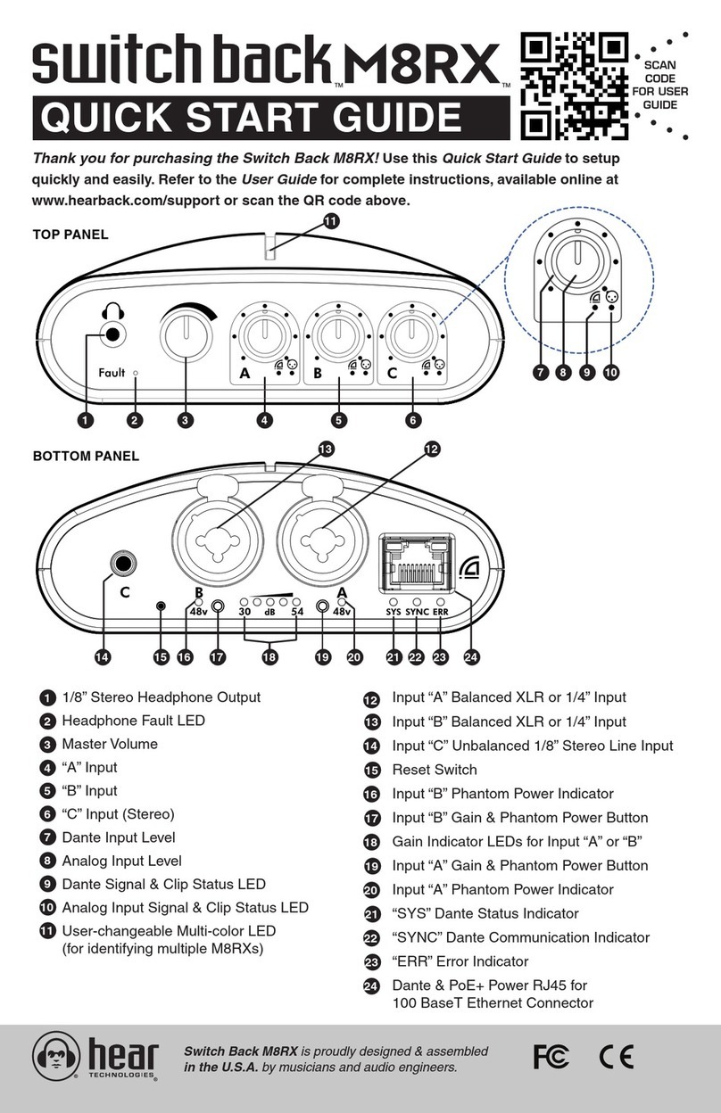
Hear Technologies switch back M8RX User manual


Switch Back
M8RX
OCTO Hub
Switch Back
M8RX
PRO Hub
FCC STATEMENT
Note: This equipment has been tested and found to comply with the limits for a Class A digital device, pursuant to part 15 of the FCC
Rules.These limits are designed to provide reasonable protection against harmful interference in a commercial installation.This equipment
generates, uses and can radiate radio frequency energy and, if not installed and used in accordance with the instructions, may cause
harmful interference to radio communications. However, there is no guarantee that interference will not occur in a particular installation. If
this equipment does cause harmful interference to radio or television reception, which can be determined by turning the equipment off and
on, the user is encouraged to try to correct the interference by one or more of the following measures:
• Reorient or relocate the receiving antenna.
• Increase the separation between the equipment and receiver.
• Connect the equipment into an outlet on a circuit different from that to which the receiver is connected.
• Consult the dealer or an experienced radio/TV technician for help.
NOTES ABOUT THE SYSTEM
If the Mixer detects a headphone short, it will automatically mute the output in attempt to keep from damaging the headphones.
WARNING
DO NOT CONNECT M8RX TO A PRO HUB OR OCTO HUB. Damage to either system can occur!

Switch Back M8RX User Guide
17. The apparatus shall be connected to a mains socket outlet with a
protective earthing connection.
18. Mains plug is used as the disconnect device. It shall remain
readily operable and should not be obstructed during intended
use.
19. WARNING: To prevent injury, this apparatus must be securely
attached to a rack in accordance with the installation instructions.
20. Detailed installation instruction in user manual.
i

Switch Back M8RX User Guide
ii

Switch Back M8RX User Guide
ELECTROMAGNETIC COMPATIBILITY
This device complies with part 15 of the FCC Rules and the Product Specifications noted on the Declaration of Conformity. Operation is
subject to the following two conditions:
• this device may not cause harmful interference, and
• this device must accept any interference received, including interference that may cause undesired operation.
Operation of this unit within significant electromagnetic fields should be avoided.
• use only shielded interconnecting cables.
WARNING
The Hub unit produces heat while powered, and therefore requires adequate ventilation to ensure the internal temperature stays
within maximum operating temperatures (0° C to 54.5° C, or 32° F to 130° F).
Please ensure that these clearances are met:
• 0.85 inches of clearance on either side of Hub
• 1 inch of clearance in front of Hub
• 11 inches of clearance in back of Hub
Care should be taken so that the Mixer’s ventilation holes remain unblocked, allowing adequate airflow through both sides of
the unit.
If you want to dispose this product, do not mix it with general household waste.There is a separate
collection system for used electronic products in accordance with legislation that requires proper
treatment, recovery and recycling.
Private household in the 25 member states of the EU, in Switzerland and Norway may return their used electronic products free of charge
to designated collection facilities or to a retailer (if you purchase a similar new one).
For countries not mentioned above, please contact your local authorities for a correct method of disposal.
By doing so, you will ensure that your disposed product under goes the necessary treatment, recovery and recycling and thus prevent
potential negative effects on the environment and human health.
DECLARATION OF CONFORMITY
Manufacturer’s Name: Hear Technologies
Manufacturer’s Address: 991 Discovery Dr.
Huntsville, AL 35806, USA
Declares that the product:
Product Name: Switch Back M8RX
Product Option: All (requires Class II power adapter
that conforms to the requirements of
EN60065, EN60742, or equivalent.)
Conforms to the following Product Specifications:
Safety: IEC 60065 -01+Amd 1
EMC: EN 55022:2010
55024:2010
FCC Part 15
Supplementary Information:
The product herewith complies with the requirements of the:
Low Voltage Directive 2006/95/EC
EMC Directive 2004/108/EC
RoHS Directive 2002/95/EC
WEEE Directive 2002/96/EC
EC Regulation 278/2009
With regard to Directive 2005/32/EC and EC Regulation
1275/2008 of 17 December 2008, this product is designed,
produced, and classified as Professional Audio Equipment
and thus is exempt from this Directive.
Nason Tackett
Senior Design Engineer
Hear Technologies
991 Discovery Drive
Huntsville, AL 35806, USA
Date: March 1, 2018
iii

Switch Back M8RX User Guide
iv
LIMITED WARRANTY
Hear Technologies warrants the equipment against defects in materials
and labor for a period of one year from the original date of purchase. The
duration of this warranty is limited to claims made to Hear Technologies
within the periods stated with respect to parts and labor from the date
of purchase. During the warranty period, defective equipment will
be replaced or repaired to the general condition as received, at the
discretion of Hear Technologies.
All transportation is the responsibility of the purchaser or owner.
Equipment should be shipped in the original shipping box.
This warranty applies only to defects in materials and workmanship and
does not cover failure or damage due to shipping loss or damage, abuse,
misuse, misapplication, incorrect or varying power line voltages, lack
of proper maintenance, natural disasters, acts of God, or unauthorized
modifications, repairs, or any alterations done without the expressed
written consent by Hear Technologies. Hear Technologies shall not be
liable for any loss of use of the equipment, or consequential damages,
including damages to other parts of the installation in which the
equipment is a part.
Hear Technologies does not make any warranty, express or implied,
other than the warranty contained herein. No agent, representative, or
employee has the authority to increase or alter the liability, obligations,
and terms of this warranty or sale of the equipment. NOTE: It is strongly
recommended that any equipment returned to Hear Technologies be
properly packaged and insured for its full value in case of loss, handling
or shipping damage.
Hear Technologies shall not be responsible for damage or loss of
equipment during shipment.
The following are registered trademarks of Hear Technologies:
Hear Technologies, Hear Back, Control Your Mix, Talk Back, Extreme Extender, Hearbuds, HearBus, and the “Jack” logo.
All names and marks of other companies belong to those respective companies.

Switch Back M8RX User Guide 1
OVERVIEW
The Switch Back M8RX™ is a personal interface to be
used for live sound or recording, and also a multi-channel
headphone monitoring system. While compact in size,
the M8RX gives individuals options to use it in multiple
ways, such as a mini recording studio setup or a simple
communication system.
The M8RX features a total of eight channels of audio mixing
– two channels with studio-quality microphone preamps,
two channels of line-level inputs, and four Dante network
audio inputs/outputs. The M8RX’s two mic preamps have
a distortion spec below 0.001% along with zero-latency
analog mixing and monitoring of the four analog inputs. With
Ethernet capability becoming standard in most pro audio
gear today, the M8RX includes a total of four channels of
Dante network audio inputs/outputs. The sleek look and feel
makes it perfect for clipping to a belt, mounting on a mic
stand, or sitting on a table.
Along with the same high quality headphone amplifier as
in the Hear Back PRO and OCTO systems, the M8RX has
5 watts of headphone power and can be connected to a
computer via the Ethernet port using an external power
injector. The M8RX utilizes PoE+ (Power-over-Ethernet+),
which allows the unit to be powered over the same Cat6
cable used to transmit data.
ADVANTAGES / FEATURES
• 4x4 Dante I/O (4 Dante Inputs and 4 Dante
Outputs)
• Easy access to all volume controls on face
of unit
• Compact, concentric volume knobs allow
volume control of local inputs using the tip, and
Dante inputs using the rings
• Master volume control for headphones
• True 48-volt phantom power remotely/locally
selectable on each microphone input
• Burr-Brown 24-bit Delta-Sigma (ΔΣ) A/D
converters
• Burr-Brown 24-bit enhanced multilevel delta-
sigma (ΔΣ) D/A conversion
• Dual-color signal and peak indicators on each
input channel
• Gain, phantom power, and Dante status
indictors tucked away on rear of unit
• Streamlined cable connections on rear of unit
• Combo XLR & 1/4” TRS balanced inputs on
channels 1 & 2 for connecting microphones or
instruments
• Balanced 1/4” inputs automatically have 18dB
of padding over XLR inputs
• 1/8” unbalanced stereo input for auxiliary
sources such as metronome, iPod, external
microphone preamp, etc.
• 100 BaseT Ethernet
• Powered by PoE+
• Remotely/Locally selectable LED color on top
for easy color-coding and identification
MADE IN THE U.S.A.

Switch Back M8RX User Guide
SYSTEM STANDOUTS
• Two ultra-low noise studio-quality discrete microphone
preamplifiers
• Remotely/Locally adjustable microphone gain, in selectable
increments between 30 and 54 dB
• Local volume control of up to 8 channels of audio (4 local
analog inputs and 4 Dante digital inputs)
• 1/8” Stereo Input (input 3/4)
• Ultra-low distortion of 0.001% THD+N (even with 60 dB of gain
on the microphone preamp!)
• PoE+ power guarantees ground isolation between M8RX
interfaces
• Standard CAT6 cabling delivers power and Dante digital audio
to each M8RX
• Zero latency headphone monitoring of the local analog
inputs
• All 4 local analog input channels are made available on
the Dante network as sources
• Optional Hear Technologies software for discovering and
controlling M8RX interfaces on the network
• Small enough to be clipped on your belt (with the included
belt clip) or mount on a stand using the built-in standard
camera-tripod mount (¼”-20 thread)
• Can use stand-alone (without a Dante network
connection) as a small microphone preamp, analog mixer,
and headphone amplifier (great as a more-me system)
1/8” Stereo Headphone Output
Headphone Fault LED
Master Volume
Dante Input “A” Level
Analog Input “A” Level
Dante “A” Signal & Clip Status LED
Analog “A” Signal & Clip Status LED
Dante Input “B” Level
Analog Input “B” Level
Dante “B” Signal & Clip Status LED
Analog “B” Signal & Clip Status LED
Dante Input “C” Level (Stereo)
Analog Input “C” Level
Dante “C” Signal & Clip Status LED
Analog Input “C” Signal & Clip Status LED
User-changeable Multi-color LED
(for identifying multiple M8RXs)
Input “A” Balanced XLR or 1/4” Input
Input “B” Balanced XLR or 1/4” Input
Input “C” Unbalanced 1/8” Stereo Line Input
Reset Switch
Input “B” Phantom Power Indicator
Input “B” Gain & Phantom Power Button
Gain Indicator LEDs for Input “A” or “B”
Input “A” Gain & Phantom Power Button
Input “A” Phantom Power Indicator
“SYS” Dante Status Indicator
“SYNC” Dante Communication Indicator
“ERR” Error Indicator
Dante & PoE+ Power RJ45 for 100 BaseT
Ethernet Connector
¼”-20 Thread Standard Camera-Tripod Mount
2
1
2
3
4
5
6
7
8
9
DETAIL DIAGRAM
10
11
13
14
15
16
21
22
23
24
25
26
27
28
30
13
12 14
27 28 292625242322212019
18 17
12
17
18
19
20
29
30
TOP PANEL
BOTTOM PANEL
REAR PANEL

Switch Back M8RX User Guide 3
CONTROLS
The M8RX has three different types of controls:
1. INPUT VOLUME KNOB – There are 3 input
volume knobs labeled “A”, “B”, and “C”. Each of these knobs
has two parts that can be adjusted independently: a tip
and a ring. The tip of each volume knob adjusts the level of
each analog input located on the bottom of the M8RX. The
ring of each volume knob adjusts the level of each Dante
input which arrives over the Ethernet network connection.
These can be assigned from any other Dante device on the
network using the Dante Controller software. These volume
knobs only adjust the audio level to the headphones, they
do not affect the audio level sent to the Dante network.
2. MASTER VOLUME KNOB – The master volume is used
to set the overall volume level of the headphone output.
3. INPUT GAIN PUSH BUTTON – Each button is
located below its respectful channel’s XLR inputs on the
bottom of the M8RX. Pushing one of these buttons will
display the current input gain for the chosen input on the
5 GREEN LED indicators below and between the two
XLR inputs. Every press of this button after the initial press
will step the gain up or down one step. The gain first steps
up until it gets to the top, and then it steps back down until
it gets to the bottom and continues to repeat this pattern.
Gain has input sensitivity adjustments from -54dBu to
-30dBu for XLR microphone inputs (-36dBu to -12dBu for
¼” inputs). Holding one of these push buttons for 2 seconds
will toggle the phantom power for the input which is
indicated by an ORANGE LED below the XLR input .
Pushing and holding both of these buttons at the same time
will cycle through colors on the font color-changing LED .
These buttons can also be locked or unlocked (see page 4).
INPUTS
The M8RX has three different types of inputs:
1. BALANCED MONO INPUT – The M8RX has two balanced
mono inputs labeled “A” and “B” . These inputs have
a special “combo” connector that allows either a XLR
microphone connector or a ¼” TRS connector. The XLR
input is designed for microphones and has adjustable input
gain with sensitivity adjustments from -54dBu to -30dBu
and a 48 volt phantom power supply that is selectable
per input. The ¼” input has an 18 dB pad and is designed
for line-level and instrument inputs with input sensitivity
adjustments from -36dBu to -12dBu. These two inputs can
be monitored locally in the analog domain (zero latency)
by turning up the tips of volume knobs “A” and “B”
respectively. These inputs are also available on the Dante
network as channels 1 and 2.
2. UNBALANCED STEREO INPUT – The M8RX has one
unbalanced stereo input on a 1/8” TRS connector labeled
“C” . This input is designed for line-level sources and
has a fixed input gain sensitivity of -10dBu. This input can
be monitored locally in the analog domain (zero latency) by
turning up the tip of volume knob “C” . This input is also
available on the Dante network as channels 3 (left) and 4
(right).
3. DANTE DIGITAL INPUT – The M8RX has 3 channels of
digital audio inputs from the Dante network. These can be
monitored using the rings on volume knobs “A” , “B” ,
and “C” . The first two inputs are mono and audio can
be routed to them using the Dante Controller software
on channels 1 and 2 of the M8RX. Dante input “C” is a
stereo input and audio can be routed to it using the Dante
Controller software on channels 3 (left) and 4 (right).
Note: If Dante sampling rates 88.2kHz or 96kHz are used,
only 2 channels of audio are supported: “A” and “B”.
MIXER CONSTRUCTION
The Switch Back M8RX is constructed of UV-stabilized ABS
and has a built-in standard camera tripod stand mount (1/4”-20
thread). A belt-clip with tripod threaded screw is included so that
the M8RX can be attached and worn on a belt. Additionally, a
tripod thread to microphone stand adapter (1/4”-20 to 5/8”-27) is
also included to allow mounting on a microphone stand.
STATUS INDICATORS
The M8RX has seven types of status indicators:
1. FRONT COLOR-CHANGING LED – A large color-
changing indicator is provided to allow easy identification
when multiple Switch Back M8RX interfaces are used in
a setup. The color of this indicator is user-selectable by
using the PC or MAC software (available for download
from www.hearback.com) or by pressing both input buttons
simultaneously for several seconds. This indicator will
also automatically cycle through the color spectrum when
booting and also when the identify function is triggered in
the Dante Controller software.
2. DANTE – The Dante bus has three indicators that are
bi-color. They are BLUE under normal operating conditions
and RED alerting the user a problem exists. The SYS
indicator is BLUE if at least one other Dante device is
connected to the same network, otherwise it is RED. The
SYNC indicator is BLUE if the internal clock circuitry
is operating properly, otherwise it is RED. The ERR
indicator is normally off. If there is a problem with the
firmware or memory then the ERR indicator will turn RED.
3. GAIN – Five GREEN indicator LEDs located below and
between the XLR input connectors will illuminate when one
of the input buttons is pushed (located below each XLR
input). These indicators display the current input sensitivity
for each input from -54dBu to -30dBu for XLR microphone
inputs (-36dBu to -12dBu for ¼” inputs). These indicators
will automatically turn off after a few seconds of pressing
one of the input buttons.
4. PHANTOM POWER – a single ORANGE LED
indicator is located below each XLR input with the label
“48v” below it. When illuminated, 48 volts DC is present
on XLR pins 2 and 3 with respect to pin 1. This provides
power to any microphones requiring phantom power. This
is toggled on or off by holding one of the input buttons for 2
seconds.
5. AUDIO SIGNAL – six indicator LEDs located below the
input volume controls illuminate BLUE when signal is
present and RED when the input is too strong and causing
distortion. 3 of these indicators represent the A , B ,
and C Dante inputs (red Dante logo above each) and 3
of these represent the A , B , and C analog inputs
(blue XLR logo above each).
6. HEADPHONE AMPLIFIER FAULT – The fault indicator
is normally off and only illuminates RED if an over-
current or short circuit condition occurs for a long enough
period to cause overheating of the amplifier (100°C or
212°F). Continued use of the amplifier in a fault condition
is not recommended as it can degrade the amplifier’s
performance and life.
7. DANTE FAILSAFE BUTTON – Accessible through a
small hole using a paper clip or small screw driver. Only use
this button if instructed by our technical support.
16
26
27
28
23
21 25
610
14
711 15
20
5913
3
22 24
2
17 18
59
19
13
48
12
23
21 25
16

Switch Back M8RX User Guide
EXAMPLE HOOK-UP
Digital Audio Workstation (DAW)
Dante Virtual SoundCard
OPTIONAL FOR RECORDING
Vocal Mic
BassMetronome
Headphones Headphones Headphones
Vocal Mic
Guitar
Dante Soundboard
OPTIONAL FOR LIVE
Network Switch with PoE+
Vocal Mic
Keyboard
Switch Back
M8RX
Switch Back
M8RX
Switch Bac
k
M8RX
Switch Back
M8RX
4
CONNECTING THE SYSTEM
1. Connect the appropriate input(s), as shown in the hook-up
diagram below.
2. Set all volume controls to “Off” (full counter-clock-wise
position), connect the headphones or in-ear monitors.
3. Connect the M8RX to PoE+ power such as an in-line PoE+
power injector or PoE+ network switch. The M8RX receives its
power over the Cat6 cable. The Hear Technologies PRO Mixer
Distro (Firmware Version V1.2) is a good choice for a PoE+
network switch. The M8RX can receive power on any pair of
the Cat6 cable. Since the M8RX uses 100BaseT Ethernet, the
pairs on pins 4/5 and 7/8 are unused and lend themselves for
an easy way to implement a passive power supply. 48 volts DC
can be applied to any pair and ground can be applied to any
pair. The M8RX must receive 36 – 52 volts DC with a minimum
of 320mA.
4. Adjust the level at the input source (microphone gain, Dante
source, etc.) until the RED clip LED’s on the M8RX just come
on and then reduce the input(s) until you have a bright BLUE
LED. NOTE: Adjust the source for as much signal as possible
without clipping. Higher input levels improve signal-to-noise
and dynamic range.
5. Mixer Adjustment: Once you have the signals optimized, turn
the master volume to about 12 o’clock and then raise the
desired input volumes. For pest performance, avoid adjusting
the master volume too high and running the inputs too low.
LOCK OUT GAIN/PHANTOM POWER BUTTONS
Procedure to lock out Gain/Phantom Power Buttons:
1. Unplug power.
2. Press and hold BOTH blue push buttons (A and B) while
inserting network cable to reapply power.
3. Once power is reapplied, release BOTH push buttons.
4. Press either blue button to lock or unlock the Gain/
Phantom Power. The LED on the front of the M8RX will
glow RED when LOCKED and GREEN when UNLOCKED.
5. Once set, it will take approximately 10 seconds for the
M8RX to reboot (cycles through the color scheme).
6. To change settings again, repeat the steps above.
The M8RX Control Software also allows you to lock/unlock the
gain and phantom power buttons (page 5). You can still adjust
the gain and/or turn on/off phantom power through the M8RX
Software even if the physical M8RX is locked.
HEADPHONE AMPLIFIER
When using multiple headsets, the total impedance should not
go below 16 ohms. Optimum headphone amplifier performance
is achieved with a load of 32 to 50 ohms. At 50 ohms, the
amplifier is capable of sustaining 2 watts of power! The
headphone amplifiers are very powerful and can easily damage
in-ear transducers, headphones, and your hearing; exercise
great care in adjusting the master volume. The amplifiers are
short circuit protected and have a fault indicator. To lockout the
gain and phantom power buttons via the M8RX.
WARNING
• ALWAYS turn down the “Master Volume”
down before putting on in-ear headsets or
headphones because the Switch Back M8RX is
capable of driving most headphones to extreme
levels that can damage your HEARING!
• It is the user’s responsibility to prevent hearing
damage by virtue of excessive headphone
“Master Volume” settings.
!
Headphones

Switch Back M8RX User Guide 5
M8RX CONTROL SOFTWARE
Software for Microsoft Windows and Mac are available for
download from our website (www.hearback.com). This software
allows for discovery and identification of M8RX units, as well
as remote control of the microphone gain, phantom power, and
color selection of the front LED.
Device List - shows available Switch Back M8RX interfaces
currently on the network, as well as their IP address, port,
and current sampling rate. Select a device in this list to see
the current settings
Device Name - shows the current name of the selected
M8RX. You can edit the name here if you like
Microphone Preamp gain & phantom power – allows remote
control of the preamp gain sensitivity and phantom power
Front LED color selection – move this color slider to change
the color of the font panel LED
1
2
3
4
Audio Input signal status – these indicators light up BLUE
(signal) and RED (clip) for the analog and Dante inputs the
same way they do on the physical M8RX
Identify Button – causes the M8RX unit’s front LED to cycle
through the color spectrum. Useful for identifying the physical
M8RX that corresponds to the item in the list
Dante Connection Status – Displays the current state of the
Dante network (e.g. ‘Not Connected’ if no suitable Ethernet
adapter is found)
5
6
7
NOTE: You must use a wired Ethernet connection to remote
control Dante devices. This is a restriction of Dante control. You
cannot use WiFi.
12
3
4
5
6
7

Switch Back M8RX User Guide
Above is an example of routing audio in the Dante Controller
software. Dante devices appear along the top (audio
transmitters) and along the left side (receivers). Sampling rates
must be set the same on each device before you can route audio
from a transmitter to a receiver. Green check marks indicate a
route from a transmitter to a receiver. Changes made here are
non-volatile and will remain even if the software is closed and
power is removed from the Dante devices.
6
DANTE NETWORK
With hundreds of professional audio manufacturers now
supporting Dante, it is an easy way to route multiple channels
of high quality audio at a very low latency between two or more
pieces of equipment (including directly out of a PC or Mac using
only its Ethernet port.) Dante (Digital Audio Network Through
Ethernet) is a standard audio-over-Ethernet protocol developed
and supported by Audinate Pty Ltd.
Please note that we did not develop the Dante protocol. We are
simply an end-point. In this manual, we just barely scratch the
surface of Dante’s capabilities. The creators of Dante know their
protocol better than anyone!
Please visit www.audinate.com for a vast wealth of training
videos, example setups, and documentation.
Our Switch Back M8RX connects four channels of simultaneous
audio input and output with other Dante enabled equipment
using a standard Ethernet network connection. Dante will
work with standard network switches and routers and is safe
to combine with your existing computer network, if necessary.
100BaseT network speed is supported. The M8RX supports
four channels of inputs and outputs at sampling rates of 44.1kHz
or 48kHz and two channels of inputs and outputs at sampling
rates of 88.2kHz or 96kHz.
A Dante network requires at least two devices that support the
Dante protocol and a single Cat6 network connection between
the two devices. Before you can send audio over the Dante
network, you must first connect a Windows PC or Mac running
the Dante Controller software (download from www.audinate.
com) in order to configure audio channel routing. You must
choose what you want to send to each of the four channels of
the M8RX and also if you want to route any of the audio from
the 4 inputs of the M8RX to any other Dante device. Whatever
is assigned to channels one through four in the Dante Controller
software is what will show up on channels A, B, and C on the
M8RX. A and B are mono channels and C is a stereo channel.
After configuration, the computer can be disconnected. To
connect the PC or Mac, you can connect the computer’s
Ethernet cable directly into the M8RX (using an in-line PoE+
power injector to power the M8RX) or into a PoE+ network
switch to which the other Dante devices are also connected.
DANTE CONTROLLER SOFTWARE

Switch Back M8RX User Guide
DEVICE VIEW
If you double click on a device on the routing screen, a Device
View window will appear. Below is an example of this window.
RECEIVE
The first tab shows the Receive sources. This is a good way to
see what is currently routed to a M8RX and see the status and
audio signal status. This is good for troubleshooting.
TRANSMIT
The next tab on the Device View window is the Transmit tab.
Below is an example of this window. Here you can see the audio
signal status. This is also great for troubleshooting.
7
STATUS
The next tab on the Device View window is the Status tab.
Below is an example of this window. Here you can see the
current version of Dante firmware, clock status and network
status.
DEVICE CONFIG
The Device Config tab on the Device View window is shown
below and this is where you can change the name of the Dante
device and also the sampling rate. All devices must be set
to the same sampling rate before you can route audio from a
transmitter to a receiver. If the sampling rate needs to change,
you must change it on all devices individually.

Switch Back M8RX User Guide
8
SYSTEM BLOCK DIAGRAM
TROUBLESHOOTING AND OPERATING TIPS
No Signal for Analog Input • Verify M8RX has power (front LED illuminated).
• Check input connections, input gain (in input is “A” or “B”), input volume controls, and master volume
control.
• Check output devices, headphones, wireless transmitter/receiver, monitor amplifiers, etc.
• Test input source and output device with other known good equipment to rule out the fault through a
process of elimination.
No Signal for Dante Input • Check the Dante audio signal present LED below the volume knob on the M8RX and verify volume knob
and master volume knob are turned up enough.
• Check routing in the Dante Controller software and make sure there are green check marks on the M8RX
receive channels to indicate that a source is routed.
• If there are red circle-backslash symbols on the M8RX Dante receive channels in Dante Controller, verify
that the M8RX and the source you are trying to send are set to the same sampling rate. (Dante devices do
not follow sampling rate changes. You must change the sampling rate on all devices individually in Dante
Controller).
• If there are yellow exclamation symbols on the M8RX Dante receive channels in Dante Controller, this
indicates that the source is missing from the Dante network. Verify source network connectivity and power.
Try rebooting the source device.
Input “C” is only coming out
of one ear
• Input “C” is a stereo input, you must feed audio into both channels.
• If you are using the 1/8” Analog input “C”, you must use a 3 conductor 1/8” connector (TRS) and there
must be signal on both the tip and the ring. The tip is the left ear and the ring is right ear.
• If you are using the Dante input “C”, you must route audio to both channel 3 and 4. Channel 3 is the left
ear and channel 4 is the right ear.
Power goes out and comes
back on when volume is
turned up
• The M8RX requires 15 watts of power. If you are using a PoE power supply that is not PoE+ it will typically
turn off the power to the port that the M8RX is plugged into whenever it exceeds 13 watts. You must make
sure to use PoE+ network switches and power injectors to power the M8RX.
The headphone amplifier
fault indicator is on.
• The fault indicator indicates either a short circuit or excessive load.
Unable to route audio in
Dante Controller
• Verify that the M8RX and the source you are trying to send are set to the same sampling rate. The M8RX
can only receive audio from 2 different Dante devices (2 different receive streams).
Front LED blinks red
constantly
• This indicates a communication problem between the Audinate Ultimo processor that handles the Dante
audio and the microcontroller that processes the gain and handles the push buttons and status LEDs. Try
rebooting the M8RX. If the problem persists, please contact technical support.
If you need further assistance, feel free to contact Hear Technologies technical support by phone at +1-256-922-1200 or visit our web site at
http://www.HearTechnologies.com.

Switch Back M8RX User Guide
Mono, Balanced XLR
10Hz - 120kHz +/-0.5dB (analog input to headphone output)
0.001% @ 150mV input
0.004% @ 150mV input
-86dBu @ 150mV input
-64dBu (gain at max), -30dBu (gain at min)
10 Hz - 120kHz +/-0.5dB (analog input to headphone output)
0.001% @ 1V input
0.004% @ 1V input
-91dBu @ 1V input
-13dBu (gain at max), +20dBu (gain at min)
Stereo, Unbalanced 1/8” TRS
10Hz - 120kHz +/-0.5dB (analog input to headphone output)
0.005% @ 200mV input
0.015% @ 200mV input
-70dBu @ 200mV input
-10dBu (fixed gain)
THD less than 0.01%*
1.2W
1.6W
2.0W
1.8W
1.5W
1.1W
500mW
220mW
Typically less than 0.02%
-97 dBu
122 dB
5.5” H x 4.45” W x 1.625” D (13.97 cm H x 11.30 cm W x 4.13 cm D)
9.5 oz. (0.27 kg)
Standard camera tripod thread (1/4” 20 threads per inch), belt clip, or desk mounted
PoE+ 36-52 VDC, 15 Watts max**
Inputs A & B (available on Dante network as channels 1&2)
Mic Input Configuration:
Mic Input Frequency Response:
Mic Input THD+N:
Mic Input IMD:
Mic Input X-TALK:
Mic Input Sensitivity:
Line Input Frequency Response:
Line Input THD+N:
Line Input IMD:
Line Input X-TALK:
Line Input Sensitivity:
Input C (available on Dante network as channels 3&4)
Input Configuration:
Input Frequency Response:
Input THD+N:
Input IMD:
Input X-TALK:
Input Sensitivity:
Headphone Power (per channel)
Load Impedance:
8 Ohms:
16 Ohms:
25 Ohms:
32 Ohms:
50 Ohms:
100 Ohms:
200 Ohms:
600 Ohms:
Inter Modulation Distortion:
System Noise Performance
Noise, A-Weighted:
Dynamic Range:
Physical
Size:
Unit Weight:
Mounting:
Power
Power Requirements:
TECHNICAL SPECIFICATIONS
9
*Note: 0 dBu = 0.775 Vrms. Specifications and features subject to change without notice.
**Provided by Hear Technologies PRONET or equivalent network switch with PoE+ capability.

©2021 Hear Technologies
01-2021
Other manuals for switch back M8RX
2
Table of contents
Other Hear Technologies Recording Equipment manuals
Popular Recording Equipment manuals by other brands
Instrumentation and Engineering Services
Instrumentation and Engineering Services VFR 1 user manual
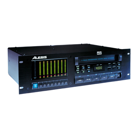
Alesis
Alesis ADAT Reference manual

Agilent Technologies
Agilent Technologies 346A Installation note
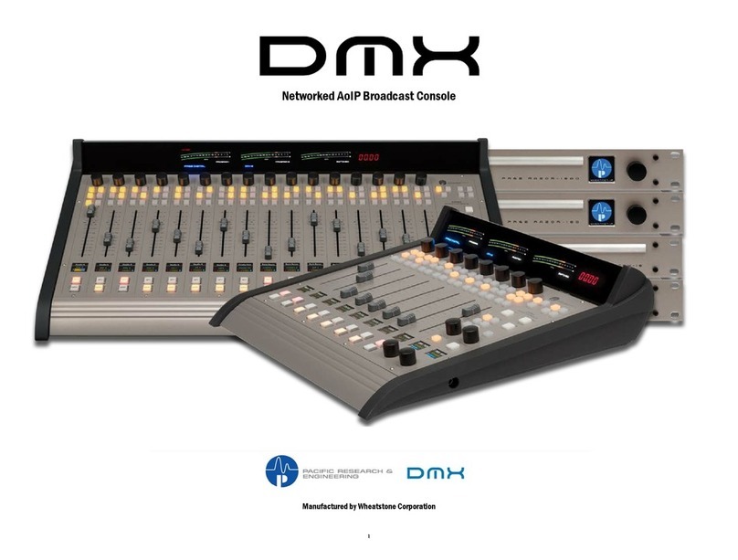
Wheatstone Corporation
Wheatstone Corporation DMX-8 manual
Yamaha
Yamaha MU1000 owner's manual

ViewTool
ViewTool Ginkgo Socket-CAN Application note

