Hearth and Home Technologies GFK-160A User manual

1
1.0 INTRODUCTION
TheGFK-160ABlowerhasbeendesignedtocirculateroom
airthroughthefireplacetoenhanceheatoutput.TheGFK160A
blower system operates on 120 VAC, 60 Hz power. This is
available through a receptacle in the factory installed junc-
tion box. The junction box is located in the controls com-
partmentofthe fireplace.
Avariablespeed control is providedwiththe blower system
toprovidequietforcedairflowatthedesiredspeeds.Atem-
peraturesensorswitch,whichautomaticallyturnsthe blower
ON/OFF, is also provided with this kit.
2.0 CHECK CONTENTS OF SHIPPING CARTON
CompareCONTENTSOFCARTONinFigure1withtheac-
tual parts received. If any parts are missing or damaged,
contact your dealer before starting installation. Do not in-
stall a damaged blower kit.
107-981K 5/03
FIGURE1
SPEED
CONTROL
TEMP.
SENSOR
SWITCH
WING
NUT
CONTROL
NUT
BLOWER
CONTROL
KNOB
GROUND
CLIP
Printed in U.S.A. Copyright 2003
Hearth & Home Technologies Inc., 20802 Kensington Blvd., Lakeville, MN 55044
GFK-160A Blower System
-InstallationandOperatingInstructions-
3.0 INSTALLATION PRECAUTIONS
The GFK-160A Blower Kit is tested and safe when installed
inaccordancewiththisinstallationmanual.Itisyourrespon-
sibility to read all instructions before starting installation and
tofollowtheseinstructionscarefullyduringinstallationtoas-
suremaximumbenefitfrom,andsafeoperationof,theblower.
This blower is carefully engineered and must be installed
only as specified. If you modify it or any of its components,
youmay cause afire hazard andwill void theWARRANTY.
Inaddition, such action may voidthe coverage providedby
theowner'shome insurance.
CAUTION: All wiring should be done by a qualified electri-
cian and shall be in compliance with local codes and with
the National Electric Code ANSI/NFPA NO. 70-current (in
theUnitedStates),orwiththecurrentCSAC22.1Canadian
ElectricCode(in Canada).
WARNING: DO NOT CONNECT110-120 VACWIRINGTO
THE GAS CONTROLVALVE OF THIS FIREPLACE.
4.0 INSTALLATION INSTRUCTIONS
4.1 INSTALLING ELECTRICAL SERVICE
TO THE JUNCTION BOX
WARNING: TURN ELECTRICAL POWER OFF AT THE
CIRCUITBREAKERBEFOREBEGINNING THIS INSTAL-
LATION.
1. Removetheelectricalcoverplate from the lower exterior
of the fireplace. Remove the knock-out from the plate
and attach the Romex clamp (screws to the outside).
(See Figure 2). NOTE: Some fireplace models have a
round hole through which the service wires are fed and
intowhich the Romexclamp is attached. Thesemodels
donot have acoverplate.
FIGURE2
LOWER
GRILLE COVER
PLATE
110-120 VAC
2. Feed the 110-120 VAC electrical service wires through
the Romex clamp and secure the wires to the clamp.
Reattach the cover plate to the outside of the fireplace.
3. Access the controls compartment of the fireplace to lo-
cate the Junction Box.
4. Using the wire nuts, attach the black wire to the black ser-
vice wire, the white wire to the white service wire, and the
servicegroundwiretothegroundstudofthejunctionbox.
5. Attach the junction box to the side of the unit. Insert the
rear tab of the box into the rectangular slot in the outer
wrap of the firebox. Push the front end of the box tightly
against the side of the unit, and secure the box with a
sheet metal screw (note the hole in the front end tab).
2
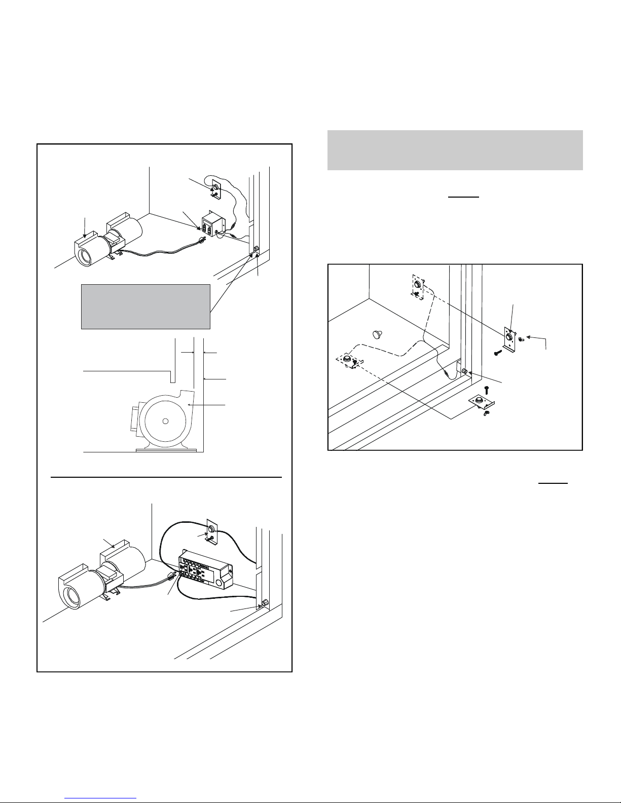
4.2 INSTALLING THE BLOWER
Positionthe blowerall the way to the rear andcenter in the
fireplace.Pull the blowerforward 1/8" to1/4" from theback
wallofthe fireplace (Figure 3).Plugthe blower cord intothe
blower receptacle FAN on the junction box. Attach the
ground wire to the bottom of the junction box or to a good
accessible metal grounded source. Note: You can attach
this to the firebox leg.
FIGURE3
BLOWER
“FAN”
RECEPTACLE
SPEED
CONTROL
SENSOR
SWITCH
NOTE: SOME MODELS MAY HAVE
A SEPARATE MOUNTING LOCATION
ON THE BASE PAN OR VALVE
BRACKET FOR MOUNTING THIS
SPEED CONTROL
FIREPLACE
WALL
BLOWER
1/8” TO 1/4”
BLOWER SENSOR
SWITCH
“FAN”
RECEPTACLE SPEED
CONTROL
METAL
STYLE
JUNCTION
BOX
POWER STRIP
STYLE
JUNCTION
BOX
4.3 INSTALLING THE SPEED CONTROL
AND SENSOR SWITCH
1. Remove the knob and locknut from the variable speed
control.Slide thecontrol behind the fireplace wall,in the
lower right front corner, with the stem sticking out of the
pre-punched hole. Attach the locknut tightly and reat-
tach the knob on the stem.
NOTE: Some models may have a separate mount-
ing location on the base pan or valve bracket for
mounting this speed control.
2. Slide the temperature sensor switch/bracket assembly
ontotheweldstudon theoutsideofthecombustioncham-
ber. Secure the bracket assembly with the wing nut pro-
vided.See Figure 4.
NOTE: The weld stud is located either on the lower right
side or the bottom of the combustion box.
NOTE: THE SWITCH/BRACKET ASSEMBLYMUST BE
INSTALLED SO THATTHE SENSOR SWITCH IS TO-
WARDSTHETOP OFTHEUNIT.
3. Connectthe variable speed controland the temperature
sensorswitchtothejunctionboxwith the wires provided.
See Figure 5 for the wiring diagram that matches the
style of junction box on the fireplace.
4. Turnthe110-120VACservice"ON"atthecircuitbreaker
and turn the speed control switch to the "ON" position.
WING
NUT
TEMPERATURE
SENSOR SWITCH
SPEED
CONTROL
FIGURE4

3
5.0 RECOMMENDED OPERATING
PROCEDURES
Ignitethefire in the fireplace withthevariable speed control
switch in an "ON" position. The fan will automatically turn
on when the temperature sensor switch closes at approxi-
mately 110OF. Heated air should be delivered at the outlet
grille. The fan will continue to operate after the fireplace is
turned OFF until the sensor switch opens.
Various conditions (such as fireplace model, type of fire-
placeinstallation,outsideairtemperaturevs.insideairtem-
perature)cancontributeto the length of thetimetheblower
remainsonafterthefireplaceisturnedOFF.The blowercan
be turned off manually with the speed control switch.
WARNING:NEVERCONTACTBLOWERWHEEL(VANES)
DURINGBLOWEROPERATION.
6.0 MAINTENANCE
Periodicallycheckthefireplacegrillesandremoveanydust,
dirt or obstructions.
7.0 REPLACEMENT PARTS AND CUSTOMER
SERVICE
Replacement parts and service may be obtained through
yourdealer.
Hardware Bag: SRV107-570A
FIGURE5 Fan WiringDiagram
NOTE: IFANY OF THE ORIGINAL WIREAS SUPPLIED
WITHTHEAPPLIANCE MUSTBE REPLACED, IT MUST
BE REPLACED WITH TYPE 105O CRATED WIRE.
BLOWER
BLOWER RECEPTACLE
BLK
WHT
WHT
GROUND
GRN
110-120 VAC
WHT
BLK
BLK
JUNCTION BOX
BLK
TEMPERATURE
SENSOR SWITCH
BLK
BLK
BLK
BLK
VARIABLE SPEED
SWITCH
GROUND
WIRE
METALSTYLEJUNCTIONBOX
POWER STRIP STYLE JUNCTION BOX
BLUE
VARIABLE
SPEED SWITCH
TEMPERATURE
SENSOR SWITCH
JUNCTION BOX
NOTE: IFANY OF THE ORIGINAL WIREAS SUPPLIED
WITHTHEAPPLIANCE MUSTBE REPLACED, IT MUST
BE REPLACED WITH TYPE 105O CRATED WIRE.
Other Hearth and Home Technologies Blower manuals


