Heat Wave NP5880 Quick start guide

NP5880
PREMIUM COVER LIFT
Assembly, Installation, and Use Instructions
Questions, problems, missing parts?
Before returning to your retailer, call our Consumer Hotline at 1-800-759-0977,
Monday – Friday, 8 a.m. – 5 p.m. (CST).
F. Push the cover
downward
13. To use the Cover Caddy, follow the steps in Fig 13.
Figure 13
B. Rotate the arms outward and make
sure the spring pins lock.
D. Fold the cover in half
E. Slide the cover in between
the U-Arms
C. Cover Caddy deployed
A. Cover on the spa with Cover Caddy
stowed
V1: 122020
NP5880
(Spa and spa cover
not included)

2
THANK YOU!
!SAFETY INFORMATION
ASSEMBLY TIPS
Thank you for purchasing this product! We work around the clock and around the globe to ensure
that our products maintain the highest possible quality. However, in the rare case of issues during
assembly or use of this product, please contact our Consumer Hotline at 1-800-759-0977 for immediate
assistance before contacting your retailer. Please read the warranty information at the end of this User
Manual for further details.
Please read and understand this entire manual before attempting to assemble, install, or operate
the product.
• Layout all the parts and verify that they are all present according to the Parts and Hardware list.
• Some gures or drawings may not look exactly like the product.
• Hand-tighten all bolts in place and then tighten with a wrench once fully assembled.
CHOKING HAZARD
ITEM CONTAINS SMALL PARTS
NOT FOR CHILDREN UNDER 3 YEARS
RISQUE D'ÉTOUFFEMENT! L'ARTICLE CONTIENT DE PETITES
PIÈCES PAS POUR LES ENFANTS DE MOINS DE 3 ANS
WARNING!
ATTENTION!
TSCA Title VI Compliant California 93120
Compliant for Formaldehyde Phase II
Conformité TSCA Title IV Californie 93120
Conforme for Formaldéhyde Phase II
COMPLIANCE
CONFORMITÉ
CANCER AND
REPRODUCTIVE HARM
CANCER ET TROUBLES DE LA REPRODUCTION
WWW.P65WARNINGS.CA.GOV
WARNING!
ATTENTION!

3
Cover Caddy Installation Instructions
1. Lay out all the parts and verify that they are all present according to the Cover Caddy Parts and
Hardware List. See Fig 1.
Figure 1
Name
Quantity Part Description
ccAA
1Main Unit
ccBB
2U-Arm, w/out extension (Left)
ccCC
2U-Arm, w/out extension (Right)
ccDD
1Gas Shock
ccEE
1Pivot Arm
ccFF
1Base Plate
ccGG
2Support Leg
ccSPACER2
2U-Arm Extension
ccA
4Round Head Bolt
ccE
2Adjustment Bolt
ccF
2Pin
ccG
4Washer for Round Head Nut (Black)
ccH
2Washer for Adjustment Bolt (Silver)
ccK
2Lock Nut
ccL
2Ball Stud
ccN
4Round Head Nut
ccZ 4Lag Screw
FF
GG
Cover Caddy Installation Instructions
1. Lay out all the parts and verify that they are all present according to the Cover Caddy Parts and
Hardware List. See Fig 1.
Figure 1
Name Quantity Part Description
ccAA 1Main Unit
ccBB 2U-Arm, w/out extension (Left)
ccCC 2U-Arm, w/out extension (Right)
ccDD 1Gas Shock
ccEE 1Pivot Arm
ccFF 1Base Plate
ccGG 2Support Leg
ccSPACER2 2U-Arm Extension
ccA 4Round Head Bolt
ccE 2Adjustment Bolt
ccF 2Pin
ccG 4Washer for Round Head Nut (Black)
ccH 2Washer for Adjustment Bolt (Silver)
ccK 2Lock Nut
ccL 2Ball Stud
ccN 4Round Head Nut
ccZ 4Lag Screw
PARTS AND HARDWARE
ITEM PART DESCRIPTION QTY PART
NUMBER
AA Lift Assembly 1 NPP50500
BB U-Arm w/out Extension (Left) 2 NPP50501
CC U-Arm w/out Extension (Right) 2 NPP50502
DD Hydraulic Lift 1 NPP50503
EE Pivot Arm 1 NPP50504
FF Base Plate 1 NPP50505
GG Support Upright 2 NPP50506
HH U-Arm Extension 2 NPP50507
A* Round Head Bolt 4
NPP50508
E* Adjustment Bolt 2
F* Lock Pin 2
G* Washer for Round Head Nut (Black) 4
H* Washer for Adjustment Bolt (Silver) 2
K* Lock Nut 2
L* Ball Stud 2
N* Round Head Nut 4
Z* Lag Screw 4
A x 4 H x 2F x 2 L x 2E x 2 K x 2G x 4 N x 4 Z x 4
HH
BB
EE
CC
DD
AA
GG
*Items included in Hardware Pack (NPP50508)
F
N
G
A
Illustrations are not to scale.

4
ASSEMBLY INSTRUCTIONS
NOTE: IF USING A SIDE MOUNT SETUP, SKIP TO STEP 5.
STEP 1
Attach the Support Uprights (GG) to the Base
Plate (FF) using the Round Head Bolts (A),
Washers (G), and the Round Head Nuts (N).
STEP 2
Make sure the spa is empty and slide the Base
Plate/Support Upright assembly under the center
of the back of the spa cabinet. This will be the
side the spa cover will be stored behind. Make
sure the Base Plate (FF) sits at on the ground,
with no overhang off the slab or deck.
Figure 3
NOTE: IF YOU ARE USING A SIDE MOUNT SETUP, SKIP TO STEP 6
2. Attach the ccGG Support Legs to the ccFF Base Plate using the ccA Round Head Bolts, the ccG Washers,
and the ccN Round Head Nuts. See Fig 2.
Figure 2
3. Make sure the spa is empty and slide the Base Plate/Support Leg assembly under the center of the back of
the spa cabinet. This will be the side the spa cover will be stored behind. Ensure the ccFF Base Plate sits flat
on the ground, with no overhang off the slab or deck. See Fig 3.
GG
N
G
A
FF
FF

5
EE
CC
BB
GG
4. Slide the legs of the ccAA Main Unit/ccEE Pivot Arm assembly over the ccGG Support Legs. See
Fig 4.
Figure 5
5. Loosely thread the ccE Adjustment Bolt through the ccH Adjustment Bolt Washer and into the threaded
holes in the Support Legs. DO NOT tighten the adjustment screws yet. See Fig 5.
TO CONTINUE WITH BASE MOUNT SETUP, SKIP TO STEP 8
Figure 4
ASSEMBLY INSTRUCTIONS
STEP 3
Slide the legs of the Lift Assembly (AA),
with Pivot Arm (EE) attached, over the
Support Uprights (GG).
STEP 4
Loosely thread the (2) Adjustment Bolts (E)
through the (2) Adjustment Bolt Washers (H)
and into the threaded holes in the Support
Legs. DO NOT tighten the adjustment
screws yet.
TO CONTINUE WITH BASE MOUNT
SETUP, SKIP TO STEP 7.
AA
FF
(Step 8)
(Step 8)
H
E
Table of contents
Other Heat Wave Spa Accessories manuals
Popular Spa Accessories manuals by other brands
Takara Belmont
Takara Belmont YUME ESPOIR installation instructions

COVANA
COVANA EVOLUTION COVER owner's manual
Leisure Concepts
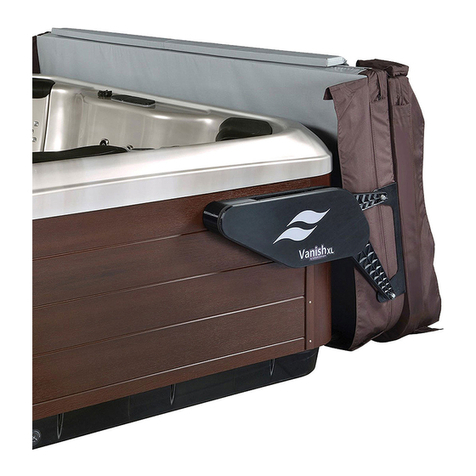
Leisure Concepts Covermate Vanish XL installation instructions
Gecko
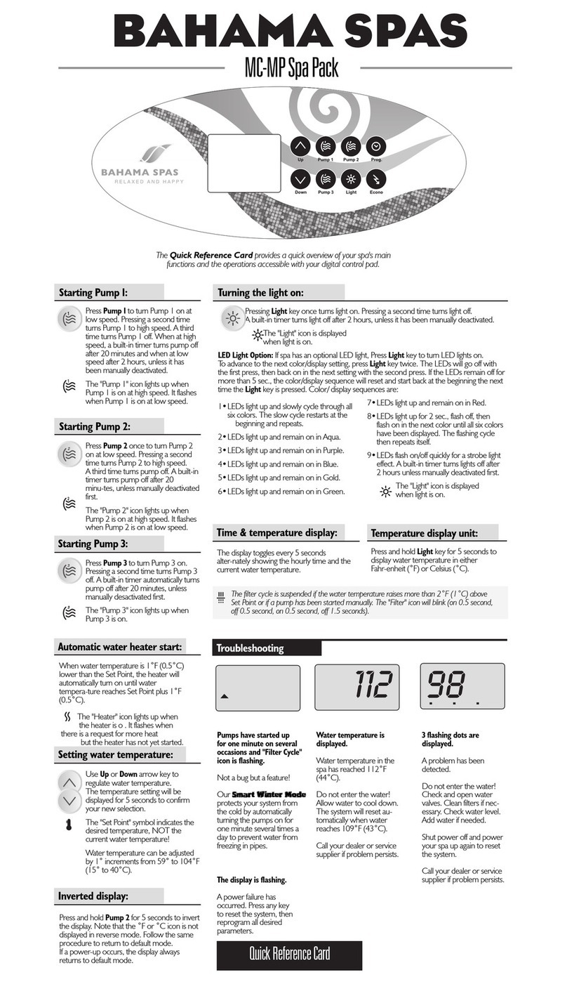
Gecko BAHAMA SPAS Quick reference card
Takara Belmont
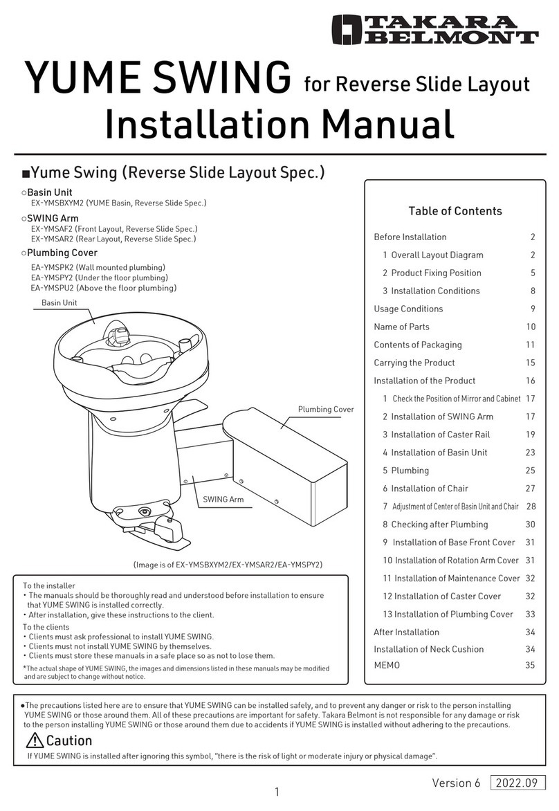
Takara Belmont YUME SWING installation manual

MAR PLAST SPA
MAR PLAST SPA KOMPATTO SPRAY SENSOR Use and maintenance manual
