Heatcraft Mohave Guide
H-IM-HGD0 FEBRUARY 2021 Part Number 25007401
Installation, Start-Up, Operation and
Troubleshooting with Wiring Diagrams
Mohave Hot Gas Defrost
Installation
& Operation
Replaces June 2017

2
Controller Quick Reference Guide.............................................................................3-5
Receiving and Inspection
General Safety Information...................................................................................... 6
Warranty Statement............................................................................................... 6
System and Components ....................................................................................... 7
Installation
Unit Cooler Installation............................................................................................ 8
Placement ............................................................................................... 9
Condensate Lines................................................................................... 10
Condensing Unit Installation
Rigging .............................................................................................. 11
Field Piping Guidelines........................................................................12-24
Optional Controls ...............................................................................25-26
System Wiring...................................................................................27-39
Operation
Hot Gas Unit Cooler Typical Factory Piping .............................................................. 40
Hot Gas Condensing Unit Typical Factory Piping ....................................................... 41
Refrigeration Operation ...................................................................................42-43
Defrost Operation ..............................................................................44-47
Evacuation & Leak Detection ................................................................................ 48
Check Out & Start-Up.......................................................................................... 49
Program Review................................................................................50-51
Monitoring & Reviewing Operation Values ............................................................... 52
Error and Alarm Details......................................................................................... 53
Refrigerant Charging.......................................................................................54-55
Operational Check Out ......................................................................................... 56
Refrigeration Oils .................................................................................... 57
Troubleshooting.................................................................................58-60
Preventive Maintenance ..................................................................................61-62
InterLink Service Parts ......................................................................................... 63
Service Record ...................................................................................... 64
Factory Default Settings...................................................................................65-68
Mohave Control Board Comparison........................................................................69
Electronic Pressure Regulator Comparison .............................................................. 70
Modbus Definitions.........................................................................................71-74
Table of Contents
© 2021 Heatcraft Refrigeration Products LLC

3
Controller Quick Reference Guide
Program
Review
Clear/
Test
Reset
Time
Monitor
Enter
Selection
Knob
Force
Service
Force
Defrost
MODE DESCRIPTION
OFF Compressor Off
COOL Compressor On in Cooling Normal Cooling Operation
PMPD System in Pump Down Mode
SERV Service Mode, System is Off
DELY Time Delay
DEF1 Defrost Stage 1
Pre-Defrost or ByPass Mode
DEF2 Defrost Stage 2
Defrost Mode
DEF3 Defrost Stage 3
Post Defrost Equalization or Drain Down Mode
FREZ Refreeze Mode
TEST Test Mode
SERV Service Mode
EVAC Evacuation Mode
Operating Modes
The Mohave™Hot Gas Controller is located inside the condensing unit electrical panel. The
Service Switch is adjacent to the controller on the side of the enclosure.
Service Switch
This toggle switch may be placed in the “on” position to force the system into Service Mode. The compressor will pump down and shut off. The evaporator fans will de-energize.
The system can be left in service.
Control Buttons
Program Review: Review or Change the Program Settings
Enter: Accepts changes into memory
Monitor: View Current Operating Conditions of the System
Reset Time: Resets the time clocks of the microprocessor to 0.
Clear/Test: Clear ignores program selections prior to pressing
Enter and terminates Service Mode. Test causes the system to
cycle through all of the outputs for troubleshooting.
Select Knob: Used for Cycling through Monitoring and
Programming Parameters.
Force Service: Press this button twice to cause the system to
pump down and remain off until the Clear button is pressed.
Force Defrost: System will pump down and begin a defrost cycle. This will not effect the normally scheduled defrosts.

4
DISPLAY DESCRIPTION FACTORY
DEFAULT
CLKH Set the Time of Day clock hour value None
CLKM Set the Time of Day clock minute value None
°F °C Set Fahrenheit or Celsius temperature units (°F or °C) °F
1224 Set Time display method (12 hr. or 24 hr.) 12 hr
ALRT Set the Alarm Time (2 to 120 minutes) 20 min
RTDF* Defrost Schedule based on Compressor Runtime OFF
DF01 Set Defrost 1 starting time (12:00 am to 12:00 pm in 30 minute increments) 12:00AM
DF02 Set Defrost 2 starting time 6:00AM
DF03 Set Defrost 3 starting time 12:00PM
DF04 Set Defrost 4 starting time 6:00PM
DF05-DF12 Set Defrost XX starting time --- ---
APPL** Set Application type (Med., Low) Med Temp
REFR Set Refrigerant type (R-22, R-404A, R-507, R-407A, R-407C, R-407F, R-448A and R-449A)” R-404A
MODL Set Model Number 1502
XPRT Expert Mode (To Access Additional Program Parameters (On, Off) Off
Program Review Menu
Monitor Display Menu
DISPLAY DESCRIPTION
VALP
Defrost Regulator Valve percent of opening (0 to 100%)
SUPH
Superheat (°F.) measured at inlet of Suction Accumulator
SucT
Suction Temperature (°F.) at inlet of Suction Accumulator
SucP
Suction Pressure (PSIG/”HG) at inlet of Suction Accumulator
SSuc
Saturated Suction Temperature (°F.) at inlet of Suction Accumulator
LIQP
Liquid Pressure (PSIG) measured between Receiver and Condenser
AMBT
Ambient Air Temperature (°F.) measured entering condenser coil
AUXT
Auxiliary Probe Temperature (°F.)
E1DT
Evaporator 1 Defrost Sensor Termination Temp (°F.) at outlet of Evaporator 1
E2DT
Evaporator 2 Defrost Sensor Termination Temp (°F.) at outlet of Evaporator 2
ACIN
Control Board voltage (24VAC nominal)
TMMS
Current time minutes and seconds
TMHM
Current time hours and minutes
CCYC
Compressor Cycles since Midnight
RnTM
Compressor Run Time since Midnight
DFTM
Duration Time of Last Defrost
ETLD
Elapsed Time since last Defrost (HH.MM)
RTLD
Run Time since last Defrost (HH.MM)
VERS
Software version
Controller Quick Reference Guide
(See Program Review Section for additional information) *Software V1.04 and higher.
**Menu re-ordered Software V2.05 and higher

5
Forced Output Menu
DISPLAY DESCRIPTION
EVPF Evaporator Fan Contactor
LIQS Liquid Line Solenoid
EVPH Evaporator Pan Heater
FAN4 Condenser Fan 4 Contactor
FAN3 Condenser Fan 3 Contactor
FAN2 Condenser Fan 2 Contactor
FAN1 Condenser Fan 1 Contactor
COMP Compressor Contactor
BYPV Bypass Solenoid
SucS Suction Stop Solenoid
DEFS Defrost Solenoid
3WAY 3-Way Valve Solenoid
ALRM Alarm Contacts
VALS Regulator Valve Control
EVAC Activate all Solenoids, Open the Pressure Regulator Valve
DISPLAY DESCRIPTION
Alr1 Persistent input sensor/transducer failure
Alr2 Combines Err4 and Err8, system off
Alr3 Repeated Safety Circuit Open condition
Alr4 Prolonged Cooling Startup Failure
DISPLAY DESCRIPTION
Err1 Suction temperature sensor open or short
Err2 Ambient temp sensor open or short
Err3 Auxiliary temp sensor open or short
Err4 Suction Pressure sensor open or short
Err5 Liquid Pressure sensor open or short
Err6 Evap 1 defrost temp sensor open or short
Err7 Evap 2 defrost temp sensor open or short
Err8 Redundant Low Pressure Switch Malfunction detected
Err9 Safety Circuit interruption during normal operation
Er10 Prolonged Low Suction Pressure during cooling
Er11 Low Suction Pressure startup failure
Er12 High Suction Pressure startup failure
Er13 Post Defrost pump down error
System Alarms
System Errors
Controller Quick Reference Guide

6
General Safety Information
1. Installation and maintenance to be performed only by
qualified personnel who are familiar with this type of
equipment.
2. Some units are pressurized with dry air or inert gas.
All units must be evacuated before charging the system
with refrigerant.
3. Make sure that all field wiring conforms to the requirements
of the equipment and all applicable national and local codes.
4. Avoid contact with sharp edges and coil surfaces.
They are a potential injury hazard.
5. Make sure all power sources are disconnected before any
service work is done on units.
WARNING: Refrigerant can be harmful if it is inhaled. Refrigerant must be used and recovered responsibly.
Failure to follow this warning may result in personal injury or death.
Inspection
Responsibility should be assigned to a dependable individual at the job site to receive
material. Each shipment should be carefully checked against the bill of lading. The
shipping receipt should not be signed until all items listed on the bill of lading have
been accounted. Check carefully for concealed damage. Any shortage or damages
should be reported to the delivering carrier. Damaged material becomes the delivering
carrier’s responsibility, and should not be returned to the manufacturer unless prior
approval is given to do so. When uncrating, care should be taken to prevent damage.
Heavy equipment should be left on its shipping base until it has been moved to the
final location. Check the serial tag information with invoice. Report any discrepancies
to your Heatcraft Refrigeration Products Sales Representative.
Warranty Statement
Seller warrants to its direct purchasers that products, including Service Parts,
manufactured by SELLER shall be of a merchantable quality, free of defects in
material or workmanship, under normal use and service for a period of one (1) year
from date of original installation, or eighteen (18) months from date
of shipment by SELLER, whichever first occurs. Any product covered by this order
found to Seller’s satisfaction to be defective upon examination at Seller’s factory will at
SELLER’s option, be repaired or replaced and returned to Buyer via lowest common
carrier, or SELLER may at its option grant Buyer a credit for the purchase price of the
defective article. Upon return of a defective product to SELLER’s plant, freight prepaid,
by Buyer, correction of such defect by repair or replacement, and return freight via
lowest common carrier, shall constitute full performance by SELLER of its obligations
hereunder.
SELLER shall have no liability for expenses incurred for repairs made by Buyer
except by prior, written authorization. Every claim on account of breach of warranty
shall be made to SELLER in writing within the warranty period specified above –
otherwise such claim shall be deemed waived. Seller shall have no warranty obligation
whatsoever if its products have been subjected to alteration, misuse, negligence,
free chemicals in system, corrosive atmosphere, accident, or if operation is contrary
to SELLER’s or manufacturer’s recommendations, or if the serial number has been
altered, defaced, or removed.
MOTOR COMPRESSORS:
Motor compressors furnished by SELLER are subject to the standard warranty
terms set forth above, except that motor compressor replacements or exchanges
shall be made through the nearest authorized wholesaler of the motor compressor
manufacturer (not at SELLER’s factory) and no freight shall be allowed for
transportation of the motor compressor to and from the wholesaler. The replacement
motor compressor shall be identical to the model of the motor compressor being
replaced. Additional charges which may be incurred throughout the substitution of
other than identical replacements are not covered by this warranty. An optional, non
assignable, four (4) year extended compressor warranty may be purchased within
the boundaries of the United Sates of America, its territories and possessions, and
Canada. With this extended compressor warranty, replacements are administered
by an authorized compressor distributor only. Replacements within the first year of
the warranty area available through the distributor; the second through fifth years,
the purchaser must submit a proof-of-purchase of a compressor and supply it to
Heatcraft Refrigeration Products Warranty Claims for reimbursement.
Seller makes no express warranties except as noted above. All implied warranties
are limited to the duration of the Express Warranty. Liability for incidental and
consequential damages is excluded.
The forgoing is in lieu of all other warranties, express or implied, notwithstanding the
provisions of the uniform commercial code, the Magnuson-Moss Warranty - Federal
Trade Commission Improvement Act, or any other statutory or common law, federal
or state.
SELLER makes no warranty, express or implied, of fitness for any particular purpose,
or of any nature whatsoever, with respect to products manufactures or sold by seller
hereunder, except as specifically set forth above and on the face hereof. It is expressly
understood and agreed that SELLER shall not be liable to buyer, or any customer of
buyer, for direct or indirect, special, incidental, consequential or penal damages, or
for any expenses incurred by reason of the use or misuse by buyer or third parties of
said products. To the extent said products may be considered "consumer products,"
As defined in Sec. 101 of the Magnuson-Moss Warranty - Federal Trade Commission
Improvement Act, SELLER makes no warranty of any kind, express or implied, to
"consumers," except as specifically set forth above and on the face hereof.
The following conditions should be adhered to when installing this unit to maintain the
manufacturers warranty:
(a) System piping must be in accordance with good
refrigeration practices.
(b) Inert gas must be charged into the piping during brazing.
(c) The power supply to the unit must meet the following conditions:
A. Three phase voltages must be +/-
10% of nameplate ratings. Single
phase must be within +10% or
-5% of nameplate ratings.
B. Phase imbalance cannot exceed 2%.
(d) All control and safety switch circuits must be properly connected
according to the wiring diagram.
(e) The factory installed wiring must not be changed without written
factory approval.
(f) All equipment is installed in accordance with Heatcraft Refrigeration
Products specified minimum clearances.
(g) Devices not provided by Heatcraft shall not be connected to the
Mohave controller without written factory approval
(h) Refrigerant line runs between condensing unit and evaporator(s) shall
not exceed 200 ft without written factory approval

7
Condensing Unit
(Vertical Air Discharge Design)
Standard Features:
• Electronic Hot Gas Defrost Controller includes Defrost Initiation and
Termination Control, Pressure Fan Cycling for Head Pressure Control, Ambient
Fan Cycling Option, Anti-Short Cycling Protection, and Low Pressure Control
• Electronic Pressure Regulator for Defrost Control
• Suction Accumulator
• High Pressure and Redundant Low Pressure Control
• Oil Pressure Safety Control
• High Efficiency Copeland Discus Compressors with POE oil
• Thermally Protected Permanently Lubricated Ball Bearing Condenser Fan
Motors
• Electrical Controls located in easily accessible control box with a hinged cover
• Receivers are sized for sufficient pump down capacity with inlet and outlet
service valves
• Cabinet is constructed from painted galvanized steel
• Convenient Access Panels for easy servicing to internal components
• Suction and Discharge Vibration Eliminators
• Separate Sub-cooling Circuit.
• Replaceable Liquid Line Filter Drier
• Replaceable Core Suction Filter
• Sight Glass
• Compressor Head Fan on L6 Models
• MODBUS RS-485 (Inherent on control board)
Optional Features:
• Head Pressure Valves (ORI/ORD)
• Oil Separator
• Insulated and Heated Receiver
• Fused Disconnect Switch
• Non-fused Disconnect Switch
• Coated Condenser Coils for protection against harsh environments (Consult
factory)
• Phase Loss Monitor
• Mounted Evaporator Control Contactors
• Remote Monitoring (RRC) Wireless Transmitter
• Variable Frequency Drive Package for Condenser Motors (Consult factory)
• Demand Cooling (Required for R-407A, R-407F, R-448A, and R-449A L6
models)
Evaporators
(Medium Profile & High Profile Unit Coolers)
Standard Features:
• All Components are factory installed and wired
• Power Supply Independent from Condensing Unit
• Mounted Fan Control Contactors and Drain Pan Heater Contactors if specified
• Four or Six Fins Per Inch Models
• Mounted TXV and Distributor Nozzle
• Mounted Check Valves
• Mounted Liquid Line Solenoid
• Suction P-Trap
• Thermally Protected Permanently Lubricated Evaporator Fan Motors
• Mounted Electric Drain Pan Heaters
• Insulated Drain Pan (Low Temperature Systems)
Optional Features:
• Mounted Hot Gas Drain Pan Loop
• Evaporator Powered from Condensing Unit
System and Components
8
top and the ceiling with an NSF listed sealant and ends of open hanger channels must
be sealed to prevent accumulation of foreign matter.
When locating unit coolers in a cooler or freezer, refer to Figure 1-2 for guidelines.
Unit Cooler Installation
Most evaporators can be mounted with rod hangers, lag screws, or bolts. Use 5/16"
bolt and washers or rod for up to 250 pounds, 3/8" for up to 600 pounds and
5/8" for over 600 pounds. Care should be taken to mount the units level so that
condensate drains properly. Adequate support must be provided to hold the weight of
the unit.
When using rod hangers, allow adequate space between the top of the unit and the
ceiling for cleaning. To comply with NSF Standard 7, the area above the unit cooler
must be sealed or exposed in such a way to facilitate hand cleaning without the use
of tools. When lagging or bolting the unit flush to the ceiling, seal the joint between the
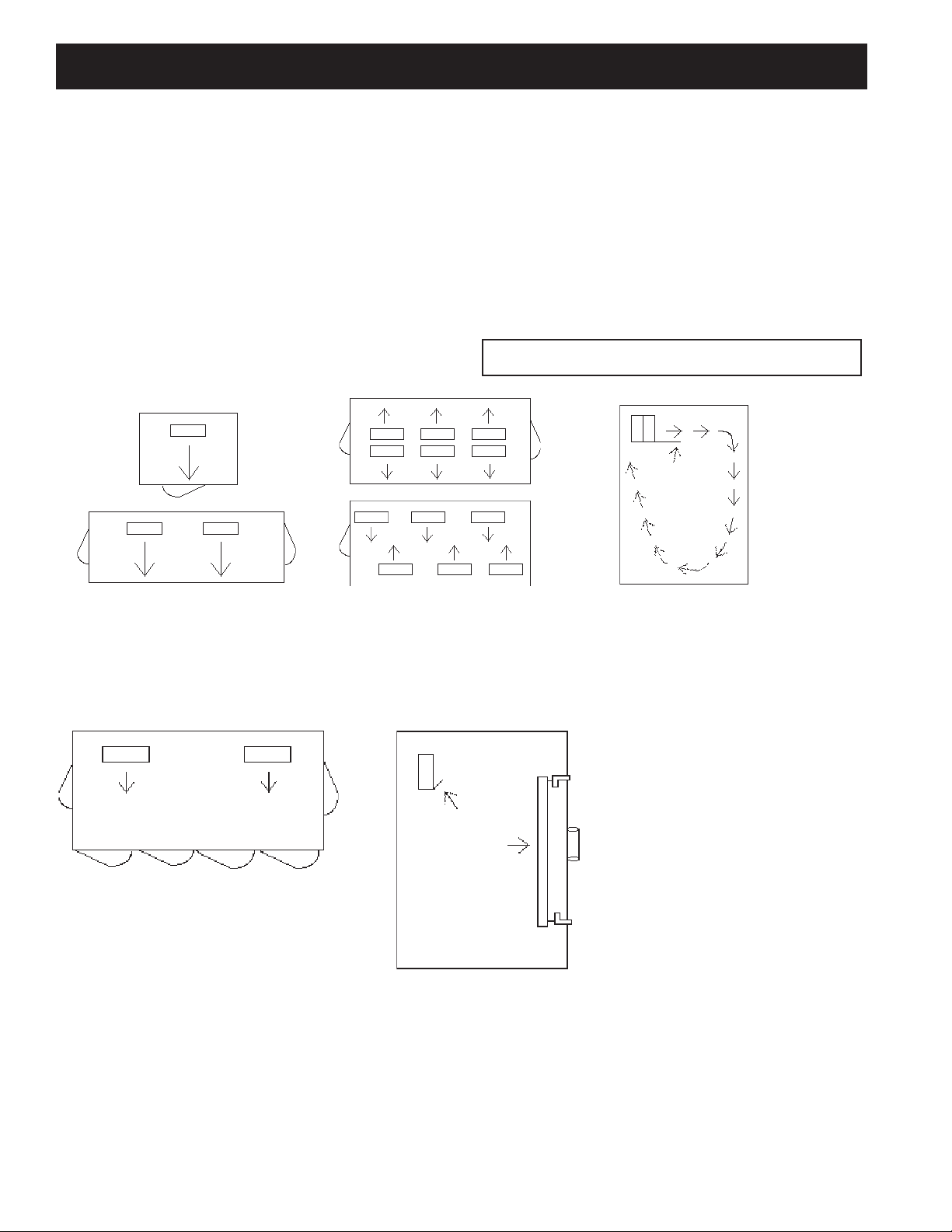
Figure 1. Large Coolers and Freezers Placement.
Where one wall evaporator mounting is
satisfactory.
Elevation view of glass display door cooler or
freezer. Be sure air discharge blows above, not
directly at doors. Provide baffle if door extends
above blower level.
Baffled Unit
Cooler or Freezer with Glass Display
Doors
Glass
Display
Door
Baffle
NOTE: Always avoid placement of Unit Coolers
directly above doors and door openings.
Cooler or Freezers where one wall will not
accommodate all required evaporators
or where air throw distance must be
considered.
Allow sufficient space between rear
of Unit Cooler and wall to permit free
return of air.
Unit Cooler Installation
9
One evaporator
Unit Coolers (continued)
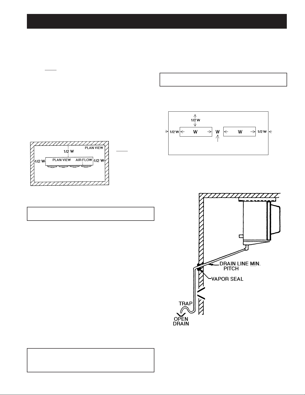
Recommended Unit Cooler Placement
Some general rules for evaporator placement which must be followed are:
1. The air pattern must cover the entire room
2. NEVER locate evaporators over doors
3. Location of aisles, racks, etc. must be known
4. Location relative to compressors for minimum pipe runs
5. Location of condensate drains for minimum run.
The size and shape of the storage will generally determine the type and number of
evaporators to be used and their location. The following are some typical examples:
Minimum Unit Clearances
Figure 2. Medium Profile and Large Unit Coolers
NOTE:
W = Total width
of evaporator
coil surface.
Two evaporators
Unit Cooler Installation & Condensate Lines
WARNING: All power must be disconnected before cleaning.
Drain pan also serves as cover of hazardous moving
parts. Operation of unit without drain pan constitutes
a hazard.
Condensate Drain Lines
Either copper or steel drain lines should be used and properly protected from
freezing. In running drain lines, provide a minimum 4 inches per foot pitch for proper
drainage. Drain lines should be at least as large as the evaporator drain connection.
All plumbing connections should be made in accordance with local plumbing codes.
All condensate drain lines must be trapped, and run to an open drain. They must
never be connected directly to the sewer system. Traps in the drain line must be
located in a warm ambient. We recommend a trap on each evaporator drain line
prior to any tee connections. Traps located outside, or extensive outside runs of
drain line must be wrapped with a drain line heater. The heater should be connected
so that it operates continuously. It is recommended that the drain line be insulated
to prevent heat loss. A heat input of 20 watts per linear foot of drain line for 0˚F
(-18˚C) room applications and 30 watts per linear foot for -20˚F (-29˚C) rooms is
satisfactory. In freezers, the evaporator drain pan fitting should be included when
heating and insulating the drain line.
Inspect drain pan periodically to insure free drainage of condensate. If drain pan
contains standing water, check for proper installation. The drain pan should be
cleaned regularly with warm soapy water.
Condensate Drain Lines
NOTE: Always trap single evaporator system drain
lines individually to prevent humidity migration.
Traps on low temperature units must be outside of refrigerated enclosures. Traps
subject to freezing temperatures must be wrapped with heat tape and insulated.
NOTE: Leave space equal to unit height between bottom of unit and product.
Do not stack product in front of fans.
- 1/4” / FT

10
The most important consideration which must be taken into account when deciding
upon the location of air-cooled equipment is the provision for a supply of ambient
air to the condenser, and removal of heated air from the condensing unit or remote
condenser area. Where this essential requirement is not adhered to, it will result in
higher head pressures, which cause poor operation and potential failure of equipment.
Units must not be located in the vicinity of steam, hot air or fume exhausts. Corrosive
atmospheres require custom designed condensers.
Another consideration which must be taken is that the unit should be mounted away
from noise sensitive spaces and must have adequate support to avoid vibration
and noise transmission into the building. Units should be mounted over corridors,
utility areas, rest rooms and other auxiliary areas where high levels of sound are
not an important factor. Sound and structural consultants should be retained for
recommendations.
Space and Location Requirements for Condensing Units and Remote Condensers
Units in Pits
The top of the unit should be level with the top of the pit, and side distance
increased to “2W”.
If the top of the unit is not level with the top of pit, discharge cones or stacks
must be used to raise discharge air to the top of the pit. This is a minimum
requirement.
Decorative Fences
Fences must have 50% free area, with 1 foot undercut, a “W” minimum
clearance, and must not exceed the top of unit. If these requirements are
not met, unit must be installed as indicated for “Units in pits”.
Walls or Obstructions
The unit should be located so that air may circulate freely and not be
recirculated. For proper air flow and access all sides of the unit should be a
minimum of “W” away from any wall or obstruction. It is preferred that this
distance be increased whenever possible. Care should be taken to see that
ample room is left for maintenance work through access doors and panels.
Overhead obstructions are not permitted. When the unit is in an area where it is
enclosed by three walls the unit must be installed as indicated for units in a pit.
Multiple Units
For units placed side by side, the minimum distance between units is
the width of the largest unit. If units are placed end to end, the minimum
distance between units is 4 feet.
Walls or Obstructions for Horizontal Air Flow Multiple Units with Horizontal Air Flow
* “W” = Total width of the condensing unit or condenser.
Space & Location Requirements for Air Cooled Condensing Units and Remote Condensers
Condensing Unit Installation

11
Figure 3. Spring Mount
Figure 5. Spring Mount
Figure 4. Solid Mount for Mobile or Deep
Sump Application.
Condensing Unit Rigging and Mounting
Rigging holes are provided on all units. Caution should be exercised when moving
these units. To prevent damage to the unit housing during rigging, cables or chains
used must be held apart by spacer bars. The mounting platform or base should be
level and located so as to permit free access of supply air.
Ground Mounting
Concrete slab raised six inches above ground level provides a suitable base. Raising
the base above ground level provides some protection from ground water and wind
blown matter. Before tightening mounting bolts, recheck level of unit. The unit should
in all cases be located with a clear space in all directions that is at a minimum, equal
to the height of the unit above the mounting surface. A condensing unit mounted in
a corner formed by two walls, may result in discharge air recirculation with resulting
loss of capacity.
Roof Mounting
Due to the weight of the units, a structural analysis by a qualified engineer may be
required before mounting. Roof mounted units should be installed level on steel
channels or an I-beam frame capable of supporting the weight of the unit. Vibration
absorbing pads or springs should be installed between the condensing unit legs or
frame and the roof mounting assembly.
Access
Provide adequate space at the compressor end of the unit for servicing. Provide
adequate space on the connection side to permit service of components.
Spring Mounted Compressor
Compressors are secured rigidly to make sure there is no transit damage. Before
operating the unit, it is necessary to follow these steps:
a. Remove the upper nuts and washers.
b. Discard the shipping spacers.
c. Install the neoprene spacers. (Spacers located in the electrical panel or
tied to compressor.)
d. Replace the upper mounting nuts and washers.
e. Allow 1/16 inch space between the mounting nut/
washer and the neoprene spacer. See Figure 3 below.
Rigid Mounted Compressor
Some products use rigid mounted compressors. Check the compressor mounting bolts
to insure they have not vibrated loose during shipment. See Figure 3 and 5 below.
Condensing Unit Installation
12
Recommended Refrigerant Piping Practices
The system as supplied by Heatcraft Refrigeration Products, was
thoroughly cleaned and dehydrated at the factory. Foreign matter may enter the
system by way of the evaporator to condensing unit piping. Therefore, care must
be used during installation of the piping to prevent entrance of foreign matter.
Install all refrigeration system components in accordance with applicable local and
national codes and in conformance with good practice required for the proper
operation of the system.
The refrigerant pipe size should be selected from the tables on pages 15-21. The
interconnecting pipe size is not necessarily the same size as the stub-out on the
condensing unit or the evaporator.
The following procedures should be followed:
(a) Do not leave dehydrated compressors or filter driers open to the
atmosphere.
(b) Use only refrigeration grade copper tubing, properly sealed against
contamination.
(c) Suction lines should slope 1/4" per 10 feet towards the compressor.
(d) Suitable P-type oil traps should be located at the base of each
suction riser to enhance oil return to the compressor.
(e) For desired method of superheat measurement, a pressure tap
should be installed in each evaporator suction line in the proximity of
the expansion valve bulb.
(f) When brazing refrigerant lines, an inert gas should
be passed through the line at low pressure to prevent
scaling and oxidation inside the tubing. Dry nitrogen is
preferred.
(g) Use only a suitable silver solder alloy on suction and liquid lines.
(h) Limit the soldering paste or flux to the minimum required to prevent
contamination of the solder joint internally. Flux only the male portion
of the connection, never the female. After brazing, remove excess flux.
(i) If isolation valves are installed at the evaporator,full port ball valves
should be used.
(j) Do not install liquid/suction line heat exchangers.
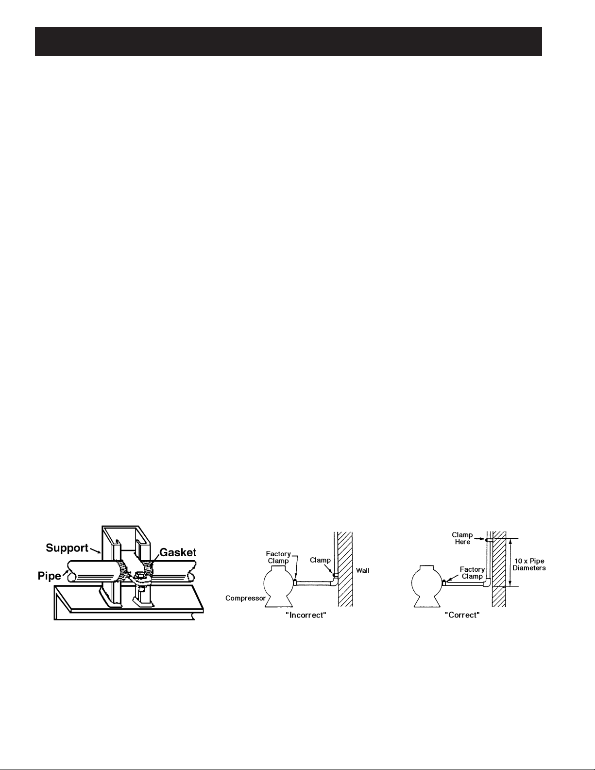
Refrigerant Pipe Support
1. Normally, any straight run of tubing must be supported in at least two locations
near each end of the run. Long runs require additional supports. The refrigerant
lines should be supported and fastened properly. As a guide, 3/8 to 7/8 should be
supported every 5 feet; 1-1/8 and 1-3/8 every 7 feet; and 1-5/8 and 2-1/8 every
9 to 10 feet.
2. When changing directions in a run of tubing, no corner should be left
unsupported. Supports should be placed a maximum of 2 feet in each direction
from the corner.
3. Piping attached to a vibrating object (such as a compressor or compressor base)
must be supported in such a manner that will not restrict the movement of the
vibrating object. Rigid mounting will fatigue the copper tubing.
4. Do not use short radius ells. Short radius elbows have points of excessive stress
concentration and are subject to breakage at these points.
5. Thoroughly inspect all piping after the equipment is in operation and add
supports wherever line vibration is significantly greater than most of the other
piping. Extra supports are relatively inexpensive as compared to refrigerant loss.
Piping
Example of Pipe Support Condensing Unit / Compressor to Wall Support.

13
Piping
The following are examples of proper piping layout for typical system configurations

14
Piping

15
Pipe size example:
Given: -10°F Freezer with one system having (2) evaporators
• One condensing unit rated at 24,000 BTUH’s @ -20°F SST R404A refrigerant.
• Two evaporators each rated at 12,000 BTUH’s @ 10°F TD.
• 75 feet of actual line run between condensing unit to first evaporator and 20 feet
of actual line run between the first evaporator and the second evaporator (see
figure below).
How to figure line sizes:
1. Determine equivalent line run = actual run + valves and fitting allowances.
2. Use Line Sizing Tables on pages 16-21 to size lines.
3. Note any special considerations.
Fittings in this system:
• (6) 90° elbows in main line plus a 90° turn through a tee.
• (5) addtional 90° elbows to first evaporator.
• (4) additional 90° elbows to second evaporator.
Determine line size 1 (main line from condensing unit):
1. Main line from the condensing unit to be sized for the total capacity (balance) of
the whole system of 24,000 BTUH’s (Table 3 and 3A).
2. Refer to 24,000 @75 feet at -20°F SST R404A on the chart.
You will find the suction line to be 1 1/8" and 1/2" liquid line.
3. Refer to Table 5A. For every 1 1/8" 90° elbow you must add 3 equivalent feet of
pipe and 2 equivalent feet of pipe for each 1 1/8" tee.
Therefore, total equivalent line run =
Actual line run 75 feet
+ (6) 1 1/8" elbows @ 3' 18 feet
+ (1) 1 1/8" tee @ 2' 2 feet
Total equivalent line run 95 feet
4. Refer to Table 3A. For 95 total equivalent feet, the suction line size should be 1
3/8" and the liquid line stays at 1/2" line.
Note: The gray shaded areas on Table 2. For 24,000 BTUH’s, the maximum suction
riser is 1 1/8" to insure proper oil return and pressure drop from the bottom p-trap
to the top p-trap.
Determine line size 2 (evaporators):
1. Line sizing to each evaporator is based on 12,000 BTUH’s and equivalent
run from condensing unit. First evaporator has an 80 ft. run and the second
evaporator has a 95 ft. run.
2. Table 3 indicates 7/8" suction for the first evaporator and Table 3A indicates 1
1/8" suction for the second evaporator.
3. Refer to Table 5A. Each 7/8" 90° elbow adds 2 equivalent feet of pipe. Each
1 1/8" 90° elbow adds 3 equivalent feet and a 90° turn through a 1 1/8" tee
adds 6 equivalent feet.
4. Actual line run (evap 1) 80 feet
+ (5) 7/8" elbows @ 2' 10 feet
+ (1) 90° turn through tee @ 6' 6 feet
Total equivalent line run 96 feet
Actual line run (evap 2) 95 feet
+ (4) 1 1/8" elbows @ 3' 12 feet
Total equivalent line run 107 feet
5. Table 3A indicates 1 1/8" suction line and 3/8" liquid line from main line to
both evaporators.
Unit Cooler Piping
Evap. 1
Evap. 2
Piping
NOTE: This is a line sizing example. Use diagrams on page
13-14 for piping orientation.

16
System
Capacity
+40
˚F
Equivalent Lengths
+20
˚F
Equivalent Lengths
+10
˚F
Equivalent Lengths
25' 50' 75' 100' 150' 200' 25' 50' 75' 100' 150' 200' 25' 50' 75' 100' 150' 200'
1,000 3/8 3/8 3/8 3/8 3/8 3/8 3/8 3/8 3/8 3/8 3/8 3/8 3/8 3/8 3/8 3/8 3/8 3/8
3,000 3/8 3/8 3/8 3/8 1/2 1/2 3/8 3/8 3/8 1/2 1/2 1/2 3/8 3/8 1/2 1/2 1/2 1/2
4,000 3/8 3/8 1/2 1/2 1/2 1/2 3/8 1/2 1/2 1/2 5/8 5/8 3/8 1/2 1/2 5/8 5/8 5/8
6,000 3/8 1/2 1/2 1/2 5/8 5/8 1/2 1/2 1/2 5/8 5/8 5/8 1/2 1/2 5/8 5/8 5/8 5/8
9,000 1/2 1/2 5/8 5/8 5/8 5/8 1/2 5/8 5/8 7/8 7/8 7/8 1/2 5/8 5/8 7/8 7/8 7/8
12,000 1/2 5/8 5/8 7/8 7/8 7/8 5/8 5/8 7/8 7/8 7/8 7/8 5/8 7/8 7/8 7/8 7/8 7/8
15,000 5/8 5/8 7/8 7/8 7/8 7/8 5/8 7/8 7/8 7/8 7/8 7/8 5/8 7/8 7/8 7/8 7/8 7/8
18,000 5/8 7/8 7/8 7/8 7/8 7/8 5/8 7/8 7/8 7/8 7/8 7/8 7/8 7/8 7/8 7/8 1 1/8 1 1/8
24,000 5/8 7/8 7/8 7/8 7/8 7/8 7/8 7/8 7/8 7/8 1 1/8 1 1/8 7/8 7/8 7/8 1 1/8 1 1/8 1 1/8
30,000 7/8 7/8 7/8 7/8 1 1/8 1 1/8 7/8 7/8 7/8 1 1/8 1 1/8 1 1/8 7/8 7/8 1 1/8 1 1/8 1 1/8 1 1/8
36,000 7/8 7/8 7/8 1 1/8 1 1/8 1 1/8 7/8 7/8 1 1/8 1 1/8 1 1/8 1 1/8 7/8 1 1/8 1 1/8 1 1/8 1 1/8 1 3/8
42,000 7/8 7/8 1 1/8 1 1/8 1 1/8 1 1/8 7/8 7/8 1 1/8 1 1/8 1 1/8 1 1/8 7/8 1 1/8 1 1/8 1 1/8 1 3/8 1 3/8
48,000 7/8 7/8 1 1/8 1 1/8 1 1/8 1 1/8 7/8 1 1/8 1 1/8 1 1/8 1 3/8 1 3/8 7/8 1 1/8 1 1/8 1 1/8 1 3/8 1 3/8
54,000 7/8 1 1/8 1 1/8 1 1/8 1 1/8 1 3/8 7/8 1 1/8 1 1/8 1 1/8 1 3/8 1 3/8 1 1/8 1 1/8 1 1/8 1 3/8 1 3/8 1 3/8
60,000 7/8 1 1/8 1 1/8 1 1/8 1 3/8 1 3/8 1 1/8 1 1/8 1 1/8 1 3/8 1 3/8 1 3/8 1 1/8 1 1/8 1 1/8 1 3/8 1 3/8 1 3/8
66,000 7/8 1 1/8 1 1/8 1 1/8 1 3/8 1 3/8 1 1/8 1 1/8 1 1/8 1 3/8 1 3/8 1 3/8 1 1/8 1 1/8 1 3/8 1 3/8 1 3/8 1 5/8
72,000 7/8 1 1/8 1 1/8 1 1/8 1 3/8 1 3/8 1 1/8 1 1/8 1 1/8 1 3/8 1 3/8 1 3/8 1 1/8 1 1/8 1 3/8 1 3/8 1 3/8 1 5/8
78,000 7/8 1 1/8 1 1/8 1 3/8 1 3/8 1 3/8 1 1/8 1 1/8 1 1/8 1 3/8 1 3/8 1 5/8 1 1/8 1 1/8 1 3/8 1 3/8 1 5/8 1 5/8
84,000 1 1/8 1 1/8 1 1/8 1 3/8 1 3/8 1 3/8 1 1/8 1 1/8 1 3/8 1 3/8 1 5/8 1 5/8 1 1/8 1 3/8 1 3/8 1 3/8 1 5/8 1 5/8
90,000 1 1/8 1 1/8 1 3/8 1 3/8 1 3/8 1 5/8 1 1/8 1 3/8 1 3/8 1 5/8 1 5/8 1 5/8 1 1/8 1 3/8 1 3/8 1 5/8 1 5/8 1 5/8
120,000 1 1/8 1 3/8 1 3/8 1 5/8 1 5/8 1 5/8 1 3/8 1 3/8 1 5/8 1 5/8 1 5/8 2 1/8 1 3/8 1 5/8 1 5/8 1 5/8 2 1/8 2 1/8
150,000 1 3/8 1 3/8 1 5/8 1 5/8 1 5/8 2 1/8 1 3/8 1 5/8 1 5/8 1 5/8 2 1/8 2 1/8 1 3/8 1 5/8 1 5/8 2 1/8 2 1/8 2 1/8
180,000 1 3/8 1 3/8 1 5/8 1 5/8 2 1/8 2 1/8 1 3/8 1 5/8 1 5/8 2 1/8 2 1/8 2 1/8 1 5/8 2 1/8 2 1/8 2 1/8 2 1/8 2 1/8
210,000 1 3/8 1 5/8 1 5/8 2 1/8 2 1/8 2 1/8 1 5/8 1 5/8 2 1/8 2 1/8 2 1/8 2 1/8 1 5/8 2 1/8 2 1/8 2 1/8 2 1/8 2 5/8
240,000 1 5/8 1 5/8 2 1/8 2 1/8 2 1/8 2 1/8 1 5/8 2 1/8 2 1/8 2 1/8 2 1/8 2 5/8 1 5/8 2 1/8 2 1/8 2 1/8 2 5/8 2 5/8
300,000 1 5/8 2 1/8 2 1/8 2 1/8 2 1/8 2 5/8 1 5/8 2 1/8 2 1/8 2 1/8 2 5/8 2 5/8 2 1/8 2 1/8 2 1/8 2 5/8 2 5/8 2 5/8
360,000 1 5/8 2 1/8 2 1/8 2 1/8 2 5/8 2 5/8 2 1/8 2 1/8 2 1/8 2 5/8 2 5/8 2 5/8 2 1/8 2 1/8 2 5/8 2 5/8 2 5/8 2 5/8
480,000 2 1/8 2 1/8 2 1/8 2 5/8 2 5/8 2 5/8 2 1/8 2 5/8 2 5/8 2 5/8 3 1/8 3 1/8 2 1/8 2 5/8 2 5/8 3 1/8 3 1/8 3 1/8
600,000 2 1/8 2 5/8 2 5/8 2 5/8 3 1/8 3 1/8 2 5/8 2 5/8 2 5/8 3 1/8 3 1/8 3 1/8 2 1/8 2 5/8 3 1/8 3 1/8 3 1/8 3 5/8
Table 1. Recommended Line Sizes for R-407*
* NOTES:
1. Sizes that are highlighted indicate maximum suction line sizes that should be used for risers. Riser size should not exceed horizontal size. Properly placed suction traps must also be used for
adequate oil return. All sizes shown are for O.D. Type L copper tubing.
2. Suction line sizes selected at pressure drop equivalent to 2˚F. Reduce estimate of system capacity accordingly.
3. If system load drops below 40% of design, consideration to installing double suction risers should be made.
4. R407A, R407C, R407F
Line Sizing
SUCTION LINE SIZE
SUCTION TEMPERATURE

17
Line Sizing
Table 1A. Recommended Line Sizes for R-407 (continued)*
LIQUID LINE SIZE
Receiver to
Expansion Valve
Expansion Valve
25' 50' 75' 100' 150' 200'
3/8 3/8 3/8 3/8 3/8 3/8 1,000
3/8 3/8 3/8 3/8 3/8 3/8 3,000
3/8 3/8 3/8 3/8 3/8 3/8 4,000
3/8 3/8 3/8 3/8 3/8 3/8 6,000
3/8 3/8 3/8 3/8 3/8 3/8 9,000
3/8 3/8 3/8 3/8 3/8 3/8 12,000
3/8 3/8 3/8 3/8 3/8 3/8 15,000
3/8 3/8 3/8 3/8 1/2 1/2 18,000
3/8 3/8 3/8 1/2 1/2 1/2 24,000
3/8 1/2 1/2 1/2 1/2 5/8 30,000
3/8 1/2 1/2 1/2 5/8 5/8 36,000
3/8 1/2 1/2 1/2 5/8 5/8 42,000
1/2 1/2 1/2 5/8 5/8 5/8 48,000
1/2 1/2 1/2 5/8 5/8 5/8 54,000
1/2 1/2 5/8 5/8 5/8 5/8 60,000
1/2 1/2 5/8 5/8 5/8 7/8 66,000
1/2 5/8 5/8 5/8 5/8 7/8 72,000
1/2 5/8 5/8 5/8 7/8 7/8 78,000
1/2 5/8 5/8 5/8 7/8 7/8 84,000
1/2 5/8 5/8 7/8 7/8 7/8 90,000
5/8 5/8 7/8 7/8 7/8 7/8 120,000
5/8 7/8 7/8 7/8 7/8 7/8 150,000
7/8 7/8 7/8 7/8 1 1/8 1 1/8 180,000
7/8 7/8 7/8 7/8 1 1/8 1 1/8 210,000
7/8 7/8 7/8 1 1/8 1 1/8 1 1/8 240,000
7/8 7/8 7/8 1 1/8 1 1/8 1 1/8 300,000
7/8 1 1/8 1 1/8 1 1/8 1 1/8 1 3/8 360,000
7/8 1 1/8 1 1/8 1 3/8 1 3/8 1 3/8 480,000
1 1/8 1 1/8 1 3/8 1 3/8 1 3/8 1 3/8 600,000
* NOTES:
1. All sizes shown are for O.D. Type L copper tubing.
2 .R407A, 407C, R407F

18
* NOTES:
1. Sizes that are highlighted indicate maximum suction line sizes that should be used for risers. Riser size should not exceed horizontal size. Properly placed suction traps must also be used for
adequate oil return. All sizes shown are for O.D. Type L copper tubing.
2. Suction line sizes selected at pressure drop equivalent to 2˚F. Reduce estimate of system capacity accordingly.
3. If system load drops below 40% of design, consideration to installing double suction risers should be made.
4. R407A, R407C, R407F
Line Sizing
System
Capacity
BTU/H
SUCTION LINE SIZE
SUCTION TEMPERATURE
+20
˚F
Equivalent Lengths
+10
˚F
Equivalent Lengths
-10
˚F
Equivalent Lengths
25' 50' 75' 100' 150' 200' 25' 50' 75' 100' 150' 200' 25' 50' 75' 100' 150' 200'
1,000 3/8 3/8 3/8 3/8 3/8 3/8 3/8 3/8 3/8 3/8 3/8 1/2 3/8 3/8 3/8 1/2 1/2 1/2
3,000 3/8 3/8 1/2 1/2 1/2 5/8 3/8 1/2 1/2 1/2 5/8 5/8 1/2 1/2 5/8 5/8 5/8 7/8
4,000 3/8 1/2 1/2 1/2 5/8 5/8 1/2 1/2 1/2 5/8 5/8 7/8 1/2 5/8 5/8 5/8 7/8 7/8
6,000 1/2 1/2 5/8 5/8 7/8 7/8 1/2 1/2 5/8 5/8 7/8 7/8 1/2 5/8 5/8 7/8 7/8 7/8
9,000 5/8 5/8 7/8 7/8 7/8 7/8 5/8 5/8 7/8 7/8 7/8 7/8 5/8 7/8 7/8 7/8 7/8 1 1/8
12,000 5/8 7/8 7/8 7/8 7/8 7/8 5/8 7/8 7/8 7/8 7/8 1 1/8 7/8 7/8 7/8 7/8 1 1/8 1 1/8
15,000 5/8 7/8 7/8 7/8 7/8 1 1/8 7/8 7/8 7/8 7/8 1 1/8 1 1/8 7/8 7/8 7/8 1 1/8 1 1/8 1 1/8
18,000 7/8 7/8 7/8 7/8 1 1/8 1 1/8 7/8 7/8 7/8 1 1/8 1 1/8 1 1/8 7/8 7/8 1 1/8 1 1/8 1 1/8 1 3/8
24,000 7/8 7/8 7/8 1 1/8 1 1/8 1 1/8 7/8 1 1/8 1 1/8 1 1/8 1 1/8 1 3/8 7/8 1 1/8 1 1/8 1 1/8 1 3/8 1 3/8
30,000 7/8 7/8 1 1/8 1 1/8 1 1/8 1 3/8 7/8 1 1/8 1 1/8 1 1/8 1 3/8 1 3/8 1 1/8 1 1/8 1 1/8 1 3/8 1 3/8 1 3/8
36,000 7/8 1 1/8 1 1/8 1 1/8 1 3/8 1 3/8 1 1/8 1 1/8 1 1/8 1 3/8 1 3/8 1 3/8 1 1/8 1 1/8 1 3/8 1 3/8 1 3/8 1 5/8
42,000 1 1/8 1 1/8 1 1/8 1 3/8 1 3/8 1 3/8 1 1/8 1 1/8 1 3/8 1 3/8 1 3/8 1 5/8 1 1/8 1 3/8 1 3/8 1 3/8 1 5/8 1 5/8
48,000 1 1/8 1 1/8 1 3/8 1 3/8 1 3/8 1 3/8 1 1/8 1 1/8 1 3/8 1 3/8 1 5/8 1 5/8 1 1/8 1 3/8 1 3/8 1 3/8 1 5/8 1 5/8
54,000 1 1/8 1 1/8 1 3/8 1 3/8 1 3/8 1 5/8 1 1/8 1 3/8 1 3/8 1 3/8 1 5/8 1 5/8 1 3/8 1 3/8 1 3/8 1 5/8 1 5/8 1 5/8
60,000 1 1/8 1 1/8 1 3/8 1 3/8 1 5/8 1 5/8 1 1/8 1 3/8 1 3/8 1 5/8 1 5/8 1 5/8 1 3/8 1 3/8 1 5/8 1 5/8 1 5/8 2 1/8
66,000 1 1/8 1 3/8 1 3/8 1 3/8 1 5/8 1 5/8 1 1/8 1 3/8 1 3/8 1 5/8 1 5/8 1 5/8 1 3/8 1 5/8 1 5/8 1 5/8 1 5/8 1 5/8
72,000 1 1/8 1 3/8 1 3/8 1 5/8 1 5/8 1 5/8 1 1/8 1 3/8 1 5/8 1 5/8 1 5/8 1 5/8 1 3/8 1 5/8 1 5/8 1 5/8 1 5/8 1 5/8
78,000 1 1/8 1 3/8 1 3/8 1 5/8 1 5/8 2 1/8 1 3/8 1 3/8 1 5/8 1 5/8 1 5/8 2 1/8 1 3/8 1 5/8 1 5/8 1 5/8 1 5/8 2 1/8
84,000 1 1/8 1 3/8 1 5/8 1 5/8 1 5/8 2 1/8 1 3/8 1 3/8 1 5/8 1 5/8 2 1/8 2 1/8 1 3/8 1 5/8 1 5/8 1 5/8 2 1/8 2 1/8
90,000 1 3/8 1 3/8 1 5/8 1 5/8 2 1/8 2 1/8 1 3/8 1 5/8 1 5/8 1 5/8 2 1/8 2 1/8 1 5/8 1 5/8 1 5/8 2 1/8 2 1/8 2 5/8
120,000 1 3/8 1 5/8 1 5/8 2 1/8 2 1/8 2 1/8 1 3/8 1 5/8 2 1/8 2 1/8 2 1/8 2 1/8 1 5/8 2 1/8 2 1/8 2 1/8 2 5/8 2 5/8
150,000 1 5/8 1 5/8 2 1/8 2 1/8 2 1/8 2 1/8 1 5/8 2 1/8 2 1/8 2 1/8 2 1/8 2 5/8 2 1/8 2 1/8 2 1/8 2 5/8 2 5/8 2 5/8
180,000 1 5/8 2 1/8 2 1/8 2 1/8 2 1/8 2 5/8 1 5/8 2 1/8 2 1/8 2 1/8 2 5/8 2 5/8 2 1/8 2 1/8 2 5/8 2 5/8 2 5/8 3 1/8
210,000 1 5/8 2 1/8 2 1/8 2 1/8 2 5/8 2 5/8 2 1/8 2 1/8 2 1/8 2 5/8 2 5/8 2 5/8 2 1/8 2 1/8 2 5/8 2 5/8 3 1/8 3 1/8
240,000 1 5/8 2 1/8 2 1/8 2 1/8 2 5/8 2 5/8 2 1/8 2 1/8 2 5/8 2 5/8 2 5/8 2 5/8 2 1/8 2 5/8 2 5/8 2 5/8 3 1/8 3 1/8
300,000 2 1/8 2 1/8 2 5/8 2 5/8 2 5/8 3 1/8 2 1/8 2 5/8 2 5/8 2 5/8 3 1/8 3 1/8 2 5/8 2 5/8 2 5/8 3 1/8 3 1/8 3 5/8
360,000 2 1/8 2 1/8 2 5/8 2 5/8 3 1/8 3 1/8 2 1/8 2 5/8 2 5/8 2 5/8 3 1/8 3 1/8 2 5/8 2 5/8 3 1/8 3 1/8 3 5/8 3 5/8
480,000 2 1/8 2 5/8 2 5/8 3 1/8 3 1/8 3 5/8 2 5/8 2 5/8 2 5/8 2 5/8 3 5/8 3 5/8 2 5/8 3 1/8 3 1/8 3 5/8 3 5/8 4 1/8
600,000 2 5/8 2 5/8 3 1/8 3 1/8 3 5/8 3 5/8 2 5/8 2 5/8 3 1/8 3 1/8 3 5/8 3 5/8 3 1/8 3 1/8 3 1/8 3 5/8 4 1/8 4 1/8
Table 2. Recommended Line Sizes for R-448A/R-449A

19
Line Sizing
System
Capacity
BTU/H
SUCTION LINE SIZE
SUCTION TEMPERATURE
-20
˚F
Equivalent Lengths
-30
˚F
Equivalent Lengths
-40
˚F
Equivalent Lengths
25' 50' 75' 100' 150' 200' 25' 50' 75' 100' 150' 200' 25' 50' 75' 100' 150' 200'
1,000 3/8 3/8 1/2 1/2 1/2 1/2 3/8 3/8 1/2 1/2 1/2 5/8 3/8 1/2 1/2 1/2 5/8 5/8
3,000 1/2 1/2 5/8 5/8 7/8 7/8 1/2 1/2 5/8 5/8 7/8 7/8 1/2 1/2 5/8 5/8 7/8 7/8
4,000 1/2 5/8 5/8 7/8 7/8 7/8 5/8 5/8 5/8 7/8 7/8 7/8 1/2 5/8 5/8 7/8 7/8 7/8
6,000 5/8 5/8 7/8 7/8 7/8 7/8 5/8 5/8 7/8 7/8 7/8 7/8 5/8 5/8 7/8 7/8 7/8 1 1/8
9,000 5/8 7/8 7/8 7/8 1 1/8 1 1/8 5/8 7/8 7/8 7/8 1 1/8 1 1/8 5/8 7/8 7/8 7/8 1 1/8 1 1/8
12,000 7/8 7/8 7/8 1 1/8 1 1/8 1 1/8 7/8 7/8 7/8 1 1/8 1 1/8 1 1/8 7/8 7/8 7/8 1 1/8 1 1/8 1 1/8
15,000 7/8 7/8 1 1/8 1 1/8 1 1/8 1 3/8 7/8 7/8 1 1/8 1 1/8 1 1/8 1 3/8 7/8 7/8 1 1/8 1 1/8 1 1/8 1 3/8
18,000 7/8 1 1/8 1 1/8 1 1/8 1 3/8 1 3/8 7/8 1 1/8 1 1/8 1 1/8 1 3/8 1 3/8 7/8 1 1/8 1 1/8 1 1/8 1 3/8 1 3/8
24,000 1 1/8 1 1/8 1 1/8 1 3/8 1 3/8 1 3/8 1 1/8 1 1/8 1 1/8 1 3/8 1 3/8 1 3/8 1 1/8 1 1/8 1 1/8 1 3/8 1 3/8 1 3/8
30,000 1 1/8 1 1/8 1 1/8 1 3/8 1 3/8 1 5/8 1 1/8 1 1/8 1 3/8 1 3/8 1 3/8 1 5/8 1 1/8 1 1/8 1 3/8 1 3/8 1 3/8 1 5/8
36,000 1 1/8 1 1/8 1 3/8 1 3/8 1 3/8 1 5/8 1 1/8 1 3/8 1 3/8 1 3/8 1 3/8 1 5/8 1 1/8 1 3/8 1 3/8 1 3/8 1 5/8 1 5/8
42,000 1 1/8 1 3/8 1 3/8 1 5/8 1 5/8 1 5/8 1 1/8 1 3/8 1 3/8 1 3/8 1 5/8 1 5/8 1 1/8 1 3/8 1 3/8 1 3/8 1 5/8 1 5/8
48,000 1 1/8 1 3/8 1 3/8 1 5/8 1 5/8 1 5/8 1 1/8 1 3/8 1 3/8 1 3/8 1 5/8 1 5/8 1 1/8 1 3/8 1 3/8 1 3/8 1 5/8 1 5/8
54,000 1 3/8 1 3/8 1 5/8 1 5/8 1 5/8 1 5/8 1 3/8 1 3/8 1 3/8 1 5/8 1 5/8 2 1/8 1 3/8 1 3/8 1 3/8 1 5/8 1 5/8 2 1/8
60,000 1 3/8 1 3/8 1 5/8 1 5/8 1 5/8 2 1/8 1 3/8 1 3/8 1 5/8 1 5/8 1 5/8 2 1/8 1 3/8 1 3/8 1 5/8 1 5/8 1 5/8 2 1/8
66,000 1 3/8 1 5/8 1 5/8 1 5/8 1 5/8 2 1/8 1 3/8 1 5/8 1 5/8 1 5/8 1 5/8 2 1/8 1 3/8 1 5/8 1 5/8 1 5/8 1 5/8 2 1/8
72,000 1 3/8 1 5/8 1 5/8 1 5/8 1 5/8 2 1/8 1 3/8 1 5/8 1 5/8 1 5/8 1 5/8 2 1/8 1 3/8 1 5/8 1 5/8 1 5/8 1 5/8 2 1/8
78,000 1 5/8 1 5/8 1 5/8 1 5/8 2 1/8 2 1/8 1 5/8 1 5/8 1 5/8 1 5/8 2 1/8 2 1/8 1 5/8 1 5/8 1 5/8 1 5/8 2 1/8 2 1/8
84,000 1 5/8 1 5/8 1 5/8 2 1/8 2 1/8 2 1/8 1 5/8 1 5/8 1 5/8 2 1/8 2 1/8 2 1/8 1 5/8 1 5/8 1 5/8 2 1/8 2 1/8 2 1/8
90,000 1 5/8 1 5/8 2 1/8 2 1/8 2 1/8 2 5/8 1 5/8 2 1/8 2 1/8 2 1/8 2 1/8 2 5/8 1 5/8 1 5/8 2 1/8 2 1/8 2 1/8 2 5/8
120,000 1 5/8 2 1/8 2 1/8 2 1/8 2 5/8 2 5/8 1 5/8 2 1/8 2 1/8 2 1/8 2 5/8 2 5/8 1 5/8 2 1/8 2 1/8 2 1/8 2 5/8 2 5/8
150,000 2 1/8 2 1/8 2 1/8 2 5/8 2 5/8 2 5/8 2 1/8 2 1/8 2 1/8 2 5/8 2 5/8 2 5/8 2 1/8 2 1/8 2 5/8 2 5/8 2 5/8 2 5/8
180,000 2 1/8 2 1/8 2 5/8 2 5/8 2 5/8 3 1/8 2 1/8 2 1/8 2 5/8 2 5/8 2 5/8 3 1/8 2 1/8 2 1/8 2 5/8 2 5/8 2 5/8 3 1/8
210,000 2 1/8 2 5/8 2 5/8 2 5/8 3 1/8 3 1/8 2 1/8 2 5/8 2 5/8 2 5/8 3 1/8 3 1/8 2 1/8 2 5/8 2 5/8 2 5/8 3 1/8 3 1/8
240,000 2 1/8 2 5/8 2 5/8 2 5/8 3 1/8 3 1/8 2 5/8 2 5/8 2 5/8 3 1/8 3 1/8 3 5/8 2 5/8 2 5/8 2 5/8 3 1/8 3 1/8 3 5/8
300,000 2 5/8 2 5/8 2 5/8 3 1/8 3 5/8 3 5/8 2 5/8 2 5/8 3 1/8 3 1/8 3 5/8 4 1/8 2 5/8 2 5/8 3 1/8 3 5/8 3 5/8 4 1/8
360,000 2 5/8 2 5/8 3 1/8 3 5/8 3 5/8 4 1/8 2 5/8 3 1/8 3 5/8 3 5/8 3 5/8 4 1/8 2 5/8 3 1/8 3 5/8 3 5/8 4 1/8 4 1/8
480,000 2 5/8 3 1/8 3 1/8 3 5/8 3 5/8 4 1/8 3 1/8 3 5/8 3 5/8 4 1/8 4 1/8 4 1/8 3 1/8 3 5/8 3 5/8 4 1/8 4 1/8 4 1/8
600,000 3 1/8 3 1/8 3 1/8 3 5/8 3 5/8 4 1/8 3 1/8 3 5/8 3 5/8 4 1/8 4 1/8 5 1/8 3 1/8 3 5/8 3 5/8 4 1/8 4 1/8 5 1/8
Table 2. Recommended Line Sizes for R-448A/R-449A (continued)*

20
Table 2A. Recommended Line Sizes for R-448A/R-449A
LIQUID LINE SIZE
Receiver to
Expansion Valve
Expansion Valve
25' 50' 75' 100' 150' 200'
3/8 3/8 3/8 3/8 3/8 3/8 1,000
3/8 3/8 3/8 3/8 3/8 3/8 3,000
3/8 3/8 3/8 3/8 3/8 3/8 4,000
3/8 3/8 3/8 3/8 3/8 3/8 6,000
3/8 3/8 3/8 3/8 3/8 3/8 9,000
3/8 3/8 3/8 3/8 3/8 3/8 12,000
3/8 3/8 3/8 3/8 3/8 1/2 15,000
3/8 3/8 3/8 3/8 1/2 1/2 18,000
3/8 3/8 1/2 1/2 1/2 1/2 24,000
3/8 3/8 1/2 1/2 1/2 1/2 30,000
3/8 1/2 1/2 1/2 1/2 1/2 36,000
3/8 1/2 1/2 1/2 1/2 5/8 42,000
1/2 1/2 1/2 1/2 1/2 5/8 48,000
1/2 1/2 1/2 1/2 5/8 5/8 54,000
1/2 1/2 1/2 5/8 5/8 5/8 60,000
1/2 1/2 5/8 5/8 5/8 5/8 66,000
1/2 1/2 5/8 5/8 5/8 5/8 72,000
1/2 1/2 5/8 5/8 5/8 7/8 78,000
1/2 5/8 5/8 5/8 5/8 7/8 84,000
1/2 5/8 5/8 5/8 7/8 7/8 90,000
5/8 5/8 5/8 7/8 7/8 7/8 120,000
5/8 7/8 7/8 7/8 7/8 7/8 150,000
5/8 7/8 7/8 7/8 7/8 1 1/8 180,000
7/8 7/8 7/8 7/8 7/8 1 1/8 210,000
7/8 7/8 7/8 7/8 1 1/8 1 1/8 240,000
7/8 7/8 1 1/8 1 1/8 1 1/8 1 1/8 300,000
7/8 7/8 1 1/8 1 1/8 1 1/8 1 1/8 360,000
1 1/8 1 1/8 1 1/8 1 1/8 1 3/8 1 3/8 480,000
1 1/8 1 1/8 1 1/8 1 3/8 1 3/8 1 3/8
600,000
Line Sizing
Table of contents
Other Heatcraft Industrial Equipment manuals


