Heatcraft POLARPACK User manual

Document No.: CL232.DOC
Page No. 1 of 15
En No.: 52311
Issue: F
Date: 12-12-2013
Manufactured by Heatcraft Worldwide Refrigeration (China) for Heatcraft Australia Pty Ltd ACN 000 056 717
POLARPACK HANDBOOK
For Units up to 18 kW
THANK YOU FOR CHOOSING THE HEATCRAFT POLARPACK CONDENSING UNIT.
TO ENSURE TROUBLE FREE INSTALLATION AND COMMISSIONING, PLEASE REFER TO THE
CONTENTS OF THIS HANDBOOK.
IMPORTANT INFORMATION-
REFER TO THE SECTIONS ON “WARNINGS AND SAFEGUARDS”, AND
“INSTALLATION INSTRUCTIONS” BEFORE ATTEMPTING TO COMMISSION THIS
CONDENSING UNIT.
CONTENTS
End User Notes pg 2
Warnings and Safeguards pg 3
Purpose pg 5
Standard Design Conditions pg 5
Installation Instructions pg 6
General Commissioning & Decommissioning Guide pg 9
Material Safety Data Sheets – M.S.D.S. pg 9
Important Note pg 10
General Arrangement Drawing pg 11
Standard wiring schematics pg 12

Document No.: CL232 issue F
Page No. 2 of 15
End User Notes
General Notes
PolarPack condensing units fall under the requirements for commercial electrical equipment as per
Standards Australia guidelines. Installation and major service of this unit must be carried out by a
licensed contractor and in accordance with local regulatory guidelines.
PolarPack condensing units are supplied with a main isolation switch on the front panel. To ensure
safety, electrical control components cannot be accessed while the isolation switch is on. The switch
is pad-lockable in the “OFF” position.
Under no circumstances should anyone other than a qualified person attempt to
gain access to the interior of the unit without first ensuring electric power is
disconnected.
PolarPack condensing units have been designed for use in an outdoor environment. PolarPack
condensing units are not suitable for mobile and explosion-proof applications.
Auto Start-Up
PolarPack condensing units may start automatically without any warning. The unit is fitted with a fan
speed controller as standard, fan(s) will rev up and down, even turn on and off on demand in
response to variations in condensing pressure. Please see “Installation Instructions” for further
details.
Auto Reset
PolarPack condenser fans and compressors are thermally protected. When tripped, these
components will not operate. Once sufficiently cooled however, the component will automatically
reset and may operate without warning.
The unit is equipped with a High/Low pressure switch as standard. The switch is either a universal
selectable auto or manual reset or fixed auto/auto-reset type on both high and low sides. If universal
switch used then it is set to auto/auto at the factory. Please check the unit regarding the appropriate
pressure switch.
Routine Maintenance of Unit
Condenser:
Condenser should be cleaned at 3 monthly intervals.
System operation:
System operation should be checked every 6 months. Checks should include:
•Operating conditions such as condensing and evaporating temperatures,
compressor discharge temperature, superheat and sub-cooling, etc.
•Refrigerant charge, oil level and quality
•Electrical connections, current draw and voltage level, etc.

Document No.: CL232 issue F
Page No. 3 of 15
Warnings and Safeguards
Heatcraft Australia is very conscious of safety issues when designing and manufacturing these products, but
it is essential that the end user, installer or service personnel also exercises care when working with the units.
Important Notes
•Do NOT remove access panels without isolating power.
•Do NOT operate unit with access panels removed due to the presence of
rotating equipment.
•Do NOT operate unit with access panels removed as there will be no air
flow over the condenser.
•All controls are 230/240V.
No Smoking
Heatcraft Australia recommends No Smoking within a distance of 15 metres of the unit.
Warning – Electrical Hazard
A qualified Electrician must carry out all electrical work. All field wiring must conform to the
requirements of the equipment and all applicable National and Local Codes.
Always isolate the power to the unit before checking and / or diagnosing the units. Never work on any
electrical item without isolating or disconnecting the power supply.
Caution – Unit Pressurized
All units are pressurised with dry air or Nitrogen gas. Care must be taken to discharge the
pressurized gas prior to installing or commissioning the equipment.
Caution – Refrigerant Type
All units are designed to work effectively with fluorocarbon refrigerants including R404A, R507, R22,
R407C and R134a. Under no circumstances can a refrigerant such as Ammonia, Hydrocarbon,
Water or Glycol be used in this product.
Refrigerant can be harmful if it is inhaled and/or makes contact with exposed skin.
Refrigerant must be used and recovered responsibly. Extreme care must be taken when
handling refrigerant, as personnel injury or death may occur.
Caution – Lubricant Oil Type
All compressors are charged with PolyolEster (POE) oil. POE can be used with HCFC refrigerants,
such as R22, and HFC refrigerants, such as R404A, R507, R407C and R134a. Use ONLY POE oil,
do NOT mix POE with other oils, when using HFC refrigerants.
Warning
This indicates contents for which, if disregarded, the possibility of human death or
severe injury can be assumed.
Caution
This indicates contents for which, if disregarded, the possibility of human injury or
the possibility of material damage can be assumed.

Document No.: CL232 issue F
Page No. 4 of 15
Caution – Sharp Edges
All units are manufactured with sheet metal and in this process all care is taken to ensure the edges
are concealed. Avoid contact with sheet-metal edges and the coil fins. They can be sharp and are a
potential personal injury hazard. Please take care when accessing in or around the unit.
Warning – Qualified Personnel
All units may only be installed, commissioned, decommissioned and serviced by qualified and trained
personnel (refrigeration mechanics and/or electricians) who have sufficient knowledge in this type of
equipment. It is the purchaser’s responsibility to co-ordinate with qualified personnel as required.
Personal Protective Equipment
Heatcraft Australia recommends as a secondary safety precaution that all personnel working with the
unit wear appropriate Personal Protective Equipment (PPE) such as gloves, eyewear and footwear.
Caution – Lifting of Unit
The compressor end of the unit is to the right looking from the front (electrical box) side. Particularly
on 2 fan units, forks should be placed toward the right hand mounting foot when lifting. Slings may
be placed through the mounting feet but care must be taken to adjust the lengths appropriately to
account for the weight distribution.
Always take care to ensure a proper weight balance before lifting and moving unit.
Caution – High and Low Temperatures
Compressor housing and discharge line temperatures may reach 150°C due to failure of system
components. Wiring and other materials which could be damaged by these temperatures should not
come into contact with the housing or discharge line.
Moreover, even in normal working operation, the unit can generate very high (may exceed 100°C)
and very low (below -40°C) temperatures on compressor housing and tubing surfaces resulting in the
possibilities of severe contact burns. Special caution must be taken when working around the unit.
Caution – Deep Vacuum
Do NOT operate compressors in deep vacuum conditions as this can cause electrical failure.
Compressors should never be used to evacuate refrigeration or air conditioning systems.
Caution – Motor Protection
WARNING: Do not insert any object into operating fans. Ignoring this warning may result in
personal injury and/or severe equipment damage and consequences.
Kulthorn Kirby and Danfoss Maneurop reciprocating hermetic compressors, and external rotor motor
fans, are fitted with inherent internal line break motor protection. After opening, the protector may not
reset for several hours until the motor cools sufficiently. Do not assume that the motor has suffered
an open circuit failure without first allowing it to cool.
Dorin compressors are fitted with Thermik motor protection or a Thermistor motor protection
module which is wired in series with the other control devises to form the control circuit. The
overload type is listed on the compressors serial plate THERMIC or PTC THERMISTOR.

Document No.: CL232 issue F
Page No. 5 of 15
NEVER apply 240V across thermistor terminals. Maximum test Voltage = 3V.
The thermistor control module is a “Fail-Safe” design. The control contact opens when power
to the module is cut, and closes when power is returned only if the thermistors signal correct
operating conditions. The thermistors should never be disconnected from the module, and
the module should never be bypassed, when the unit is in operation.
In addition to the above, thermal over-current protection is fitted to the compressor contactor(s), and
MP15 PhaseFale phase failure protection is available, on three phase compressors only.Please
contact your Heatcraft sales representative for details.
The MP15 start delay function has been utilised as follows-
HP/LP alarm to pin 5- delay with memory function and light
Compressor contactor K1 Thermal Overload N/O 97-98 to pin 8 (start delay without
memory or light).
Compressor restart will be delayed by 15 minutes when activated by these 2 fault conditions.
Restarting the MP15 (toggle Circuit Breaker CB1 Off/On) will re-initialize the MP15 timer.
Caution – Internal Pressure Relief (IPR) Valve
Some hermetic compressors include an IPR valve. The IPR valve will open when the discharge
pressure exceeds the suction pressure by a certain value which is set by the compressor
manufacturer. When it has opened, the compressor sump will become warm and the compressor will
trip out on the motor protector. The unit may take 2 to 3 hours to reset and restart automatically if this
happens.
Kulthorn Kirby “AW” and Danfoss “Maneurop” compressors have an IPR valve.
Dorin compressors do NOT have an IPR valve.
Do NOT assume that a compressor that is running, but not pumping, is faulty.
Stop the compressor and allow the pressures to balance, then start the compressor again.
Purpose
PolarPack condensing units are standard OEM products of Heatcraft Australia including both
“medium” and “low” temperature application ranges. They are designed for continuously supplying
and receiving the refrigerant to and from the evaporator(s), and rejecting the heat extracted from the
cold space to surrounding atmosphere where the units are installed.
PolarPack condensing units are intended for installing in a typical ventilated indoor or outdoor
environment (Refer to the General Arrangement Drawing section for details) with the condensing
temperature no greater than 60°C and compressor return vapour temperature no greater than 20°C.
They are not intended for environments that may have harmful, corrosive or flammable atmospheres.
Marine environments are considered corrosive; please consult Heatcraft before installing in this
environment.
Standard Design Conditions
Medium temperature range condensing units are typically designed, for primary refrigerant R404A, to
be used in commercial cool room applications ranging from -20°C to +10°C saturated suction
temperature for Kulthorn Kirby compressors, -25°C to +5°C for Maneurop compressors, and –35°C
to +5°C for Dorin compressors. R507/R404A and R22 are recommended refrigerants. For R134a
usage, please refer to other sections of this booklet for control setting information etc.
Low temperature range condensing units are designed, for primary refrigerant R404A, to be used in
commercial freezer room applications ranging from -35°C to -15°C saturated suction temperature for
Kulthorn Kirby, and -40°C to -20°C for Maneurop compressors. R507 or R404A are the
recommended refrigerants.
Please refer to sales data sheet CL225 for standard PolarPack condensing unit configurations,
options offered and other detailed information such as capacity variations for other refrigerants.
For special design requirements (non standard conditions and/or refrigerants), please inquire
with your local representatives and/or Heatcraft Australia local branches, or call our national
telephone number 13 23 50 for your nearest available information resources.

Document No.: CL232 issue F
Page No. 6 of 15
Installation Instructions
Unpacking of Unit
When unpacking, check for any damage to packing material or the unit itself which may affect the
unit’s performance. If any such damage is evident, please contact your local Heatcraft branch.
Installation Location (Refer to the General Arrangement Drawing section)
If the unit is to be located in close proximity to a wall or similar obstruction, the minimum distance
from the coil face to the obstruction shall be complied with. The unit shall be mounted on a horizontal
plane surface.
The liquid sight glass is located to the right hand side of the unit (viewed from the front). Sufficient
room should be allowed to the side to view the sight glass in operation.
Connection of gauges can be achieved from the front of the unit, refer to the section on pressure
settings for more detail.
It is particularly important for the units to allow sufficient unobstructed vertical air-discharge
space above the unit to prevent warm air recirculation to the condenser.
Refrigeration Piping
Refrigeration piping work shall be carried out professionally by qualified refrigeration
mechanics in accordance with applicable national and local regulations and in conformance
with good engineering practices required for the proper operation of the refrigeration system.
All PolarPack condensing units manufactured by Heatcraft Australia are supplied clean and internally
charged with dry air or nitrogen to prevent oxidation and ingress of moisture or foreign matter. Care
shall be taken during installation of the piping to prevent entrance of foreign matter or moisture by
minimising the time that the piping is uncapped.
The interconnecting refrigeration pipe size is not necessarily the same size as the outlet on the unit.
The pipe sizes shall be selected / calculated based on the best compromise of minimizing refrigerant
pressure drop and refrigerant velocity to ensure efficient oil return. Heatcraft can provide a software
program to assist in the calculation of pipe sizes.
Horizontal suction lines shall slope towards to the units to allow the oil return freely to the compressor
by gravity. A 1:100 slope is considered sufficient. The use of oil trap and double risers may be
necessary on vertical sections. Suction line piping shall be insulated to minimise the superheat effect
to the vapour.
If in doubt during the installation, please consult with your local sales representatives and/or
application engineers from Heatcraft Australia for technical support.
Electrical Connection
All electrical connections must be carried out by a licensed
electrical contractor and in accordance with the relevant
regulations.
Both the mains supply and the control cabling must be brought into the electric box section from the
side of the unit. The cables should be passed though the glands provided before being run to the
terminals (Refer to Wiring Schematic inside electrical box cover). Refer to the name plate for all the
information regarding voltage and current for the unit.
Mains supply cabling must be in accordance with relevant standards and / or codes, eg. AS3100.
Control circuit is 240 volts. Terminals are supplied for connection of control circuit (Refer to Wiring
Schematic inside electrical box cover).
The fitted isolation switch is pad-lockable in the “OFF” position. The door is interlocked in the “ON”
position. This interlock may be defeated by depressing a small countersunk pin on the bevelled edge,
close to the “OFF” label.

Document No.: CL232 issue F
Page No. 7 of 15
Warning – Electrical Hazard
Only qualified personnel should attempt to bypass the interlock. Caution must be exercised
when working on the unit if the interlock is bypassed.
Lubrication
PolarPack compressors use PolyolEster (POE) oil. Heatcraft Australia approves the use of POE oil
for both PolarPack hermetic and semi-hermetic reciprocating compressors.
OIL LEVELS:
Kulthorn Kirby Reciprocating Hermetic Compressors: Do NOT have oil sight glasses fitted.
Oil levels on these compressors can only be checked upon removal of the compressor.
Maneurop Hermetic Compressors: The oil level should be maintained at the mid-point of the
sightglass.
Dorin Reciprocating Semi-Hermetic Compressors: The oil level should be 2 – 4 mm above the
centre of the sight glass during operation.
Caution - Notes on POE Oils
Use only POE oil with HFC refrigerants. Do NOT mix POE oil with other oils when using HFC
refrigerants (eg R404A). Small quantities of other oil types may be mixed with POE oil when
using HCFC refrigerants (eg R22).
Compressor Starting
All PolarPack condensing units use Direct-On-Line starting compressors, in single and/or three
phase, depending on size. Care should be taken to establish starting requirements for the larger
compressors due to high in-rush current.
Maximum compressor starts per hour
Kulthorn Kirby and Maneurop reciprocating hermetic compressors = 10
Dorin reciprocating semi-hermetic compressors = 15
“Soft Start” Kits
All PolarPack condensing units have the option of starting the compressor with one of the Danfoss
electronic “soft start” devices depending on the compressor’s power supply mode.
Single phase compressors: Danfoss TCI 25 Starting Torque Limiter.
Three phase compressors: Danfoss MCI 15C CI-Tronic Softer Starter.
“Soft Start” kits are designed to enable smooth starting of AC induction motors and hence to
eliminate the damaging effects on motors due to required high starting torque or high current surge.
During ramp up or soft starting, the Danfoss controller will gradually increase the voltage to the
compressor motor from the preset initial torque until it reaches full line voltage. For details please
refer to Danfoss product specifications.
System Holding Charge
The system as supplied is pressurised at the factory with Dry Air or Nitrogen gas.
If the system is not pressurised on delivery, please contact your Heatcraft branch. Care must
be taken to release the pressure before attempting to gain access to any part of the
refrigeration system.
The unit should be evacuated to a pressure of 500 microns (µmHg) prior to commissioning.
Pressure Settings
PolarPack condensing units have a maximum operating pressure of 32 Bar(abs) determined
on pressure vessels (such as liquid receivers). Thus any pressure relief device setting must
be 32 bar(abs) or lower.
Pressure limiting device settings such as the HP control must be 29 Bar(abs) or lower in
accordance with AS1677.2 that the pressure limiting device setting is no greater than 0.9
times the maximum operating pressure.

Document No.: CL232 issue F
Page No. 8 of 15
In general, Heatcraft Australia recommends 60°C condensing temperature as the maximum
operating condition, The corresponding saturation pressures from respective refrigerants shall be
regarded as HP cut-out points for safety protection purpose. For example, approximately 28 Bar(g)
for R404A, and 23 Bar(g) for R22, are acceptable.
Heatcraft Australia also recommends the LP switch to be used as a safety protection device.
Depending on the application and compressor, LP cut-in and differential points should be set with the
following considerations:
•Set the cut-out points at 3–5 K below the respective minimum design saturated suction
temperatures (Refer to the Standard Design Conditions section for saturated suction
temperature ranges).
•Set the differential to no more than 2 Bar.
•The cut-out pressure shall be in the positive pressure region.
•When the unit is installed in a cold ambient, the cut-out pressure shall be lower than the
pressure corresponding to the ambient temperature.
Access points for gauges are located on the compressor rotolock valve, base valve,
discharge and / or suction lines depending on the model of the unit. They may be accessed
either from the fan compartment access panel, or right hand side access panel. Gauge lines
can be run through holes in the base, and the access panel re-fitted to prevent air bypass.
Fan Speed Control
A fan speed controller is fitted as standard to all PolarPack condensing units. It may be a
Saginomiya or a Johnson brand controller.
“XGE-4CC30” from SAGINOMIYA SEISAKUSHO
•This controller varies the supply voltage to the condenser fan motor from 30% to at least
95% over the proportional condensing pressure band which is factory fixed at 6 Bar.
•The set point is defined at 90% supply voltage to the fan motor, and is set at 19 Bar by the
control manufacturer. By turning the setting screw clockwise, the pressure setting increases.
Turn anti-clockwise to decrease the pressure setting. It is approximately 1.5 Bar per full
(360°) turn.
•The cut-off point is defined at 30% supply voltage to the fan motor, and corresponds to 13
Bar depending on actual load and / or power supply.
•When the condensing pressure reduces to the cut-off condition, the controller will cut off the
supply to the fan and the fan will stop. The fan restarts at low speed when the pressure rises.
For details, please refer to Saginomiya product specification.
•Heatcraft factory set point for primary refrigerant R404A is 19 Bar(g) for M/T and 14 Bar(g)
for L/T units. Heatcraft Australia recommends 10 Bar(g) for R134a units.
“P215PR-9200” from Johnson Controls,
•This controller varies the supply voltage to the condenser fan motor from 30% to at least
95% over the proportional condensing pressure band which is factory fixed at 4.5±1 Bar.
•The set point is defined at 90% supply voltage to the fan motor, and is set at 19 Bar by the
control manufacturer. By turning the setting screw clockwise, the pressure setting increases.
Turn anti-clockwise to decrease the pressure setting. It is approximately 2.5 Bar per full
(360°) turn.
•The cut-off point is defined at 30% supply voltage to the fan motor, and corresponds to
14.5±1 Bar depending on actual load and / or power supply.
•When the condensing pressure reduces to the cut-off condition, the controller will cut off the
supply to the fan and the fan will stop. The fan restarts at low speed when the pressure rises.
For details, please refer to Johnson Control’s product specification.
•Heatcraft factory set point for primary refrigerant R404A is 19 Bar(g) for M/T and 14 Bar(g)
for L/T units. Heatcraft Australia recommends 16 Bar(g) for R22 and 10 Bar(g) for R134a
units.
Warning – Setting for Other Refrigerants
It is the installer’s responsibility to set the control correctly for use with refrigerants
other than R404A.
Document No.: CL232 issue F
Page No. 9 of 15
General Commissioning & Decommissioning Guide
Warning – Commissioning
Refrigeration system commissioning shall be carried out professionally by qualified
refrigeration mechanics in conformance with good engineering practices required for the
proper operation of the refrigeration system.
After all installation and electrical work is completed, the entire refrigeration system must be leak
tested. After satisfactory testing of the refrigeration system, then refrigeration lines shall be insulated
as necessary. The insulation located in outdoor environments shall be protected from UV exposure.
Before charging the refrigerant, the entire refrigeration system shall be evacuated by connecting a
good, high vacuum pump to both the high-pressure side and low-pressure side service valves or
ports.
Refrigerant charging shall be in liquid form at the high-pressure side of the system such as
condenser or liquid receiver. If the refrigerant charging must be carried out through the suction side
of the compressor, charge in vapour form only.
Double check all field wiring connections and factory terminations. Factory connections can vibrate
loose during shipment. Ensure correct fan motor rotation, airflow is induced from coil side and forced
out of fan motor side.
If fitted, ensure that the crankcase heater has been energised for a minimum 12 hours before initial
start-up and / or after prolonged shutdown periods.
After the successful start up of the system, generally check:
•Current draw and voltage levels.
•Suction superheat settings and discharge temperatures.
•Abnormal refrigeration piping vibrations.
•Oil level and refrigerant charge.
Warning – Decommissioning
In order to remove the unit from its mounting place, the following procedures need to be
carried out professionally by qualified personnel. Failure to do so may result in personal
injury or death, property damage by fire or explosion. Discharge of refrigerant to atmosphere
is illegal and may result in heavy fines by relevant regulatory authorities.
•Pump down the entire refrigerant charge into the liquid receiver or appropriate container such as
reclaim cylinder, and shut related valves. All reclaimed refrigerant that is not re-used must
be taken to an approved refrigerant recycling or destruction facility. Heatcraft Branches will
accept the used refrigerant.
•Disconnect the power supply. Remove all necessary field electrical wiring and related
components, leaving the earth wire to the last.
•Care must be taken when disconnecting the refrigeration piping because of unbalanced pressure
between the unit and ambient. There may be a small amount of refrigerant trapped in the oil, the
pressure rise in the system will boil and vaporise the refrigerant resulting in a potential personal
injury hazard.
•Cut and solder seal the refrigeration liquid line and suction line pipe connections.
•Remove the unit from its mounting place. Adequate equipment must be provided as per lifting
notes.
Material Safety Data Sheets – M.S.D.S.
These are available from your nearest Heatcraft Branch for all refrigerants that PolarPack
condensing units are approved for, and for oils and other materials as needed.

Document No.: CL232 issue F
Page No. 10 of 15
Important Notes
To ensure PolarPack condensing units operate efficiently and for a long working life, always obtain
genuine replacement parts from your local Heatcraft Wholesale Branch. Genuine replacement parts
are covered by the warranty. Refer to the Standard Terms & Conditions of Sale in the Price Guide for
warranty statements.
Continuous product improvement is our company policy. Heatcraft Australia reserves the right to
make changes in product specifications and/or this instruction manual without notice.
Heatcraft Australia is dedicated to providing safe products and protecting the environment by
complying with all applicable national laws and regulations governing environmental
protection. New and used refrigerants cannot be vented into atmosphere. Reclaim all used
refrigerants. EPA regulations are constantly updated. Ensure your refrigerant handling
procedure complies with the relevant regulations.

Document No.: CL232 issue F
Page No. 11 of 15
General Arrangement Drawing
Document No.: CL232 issue F
Page No. 12 of 15
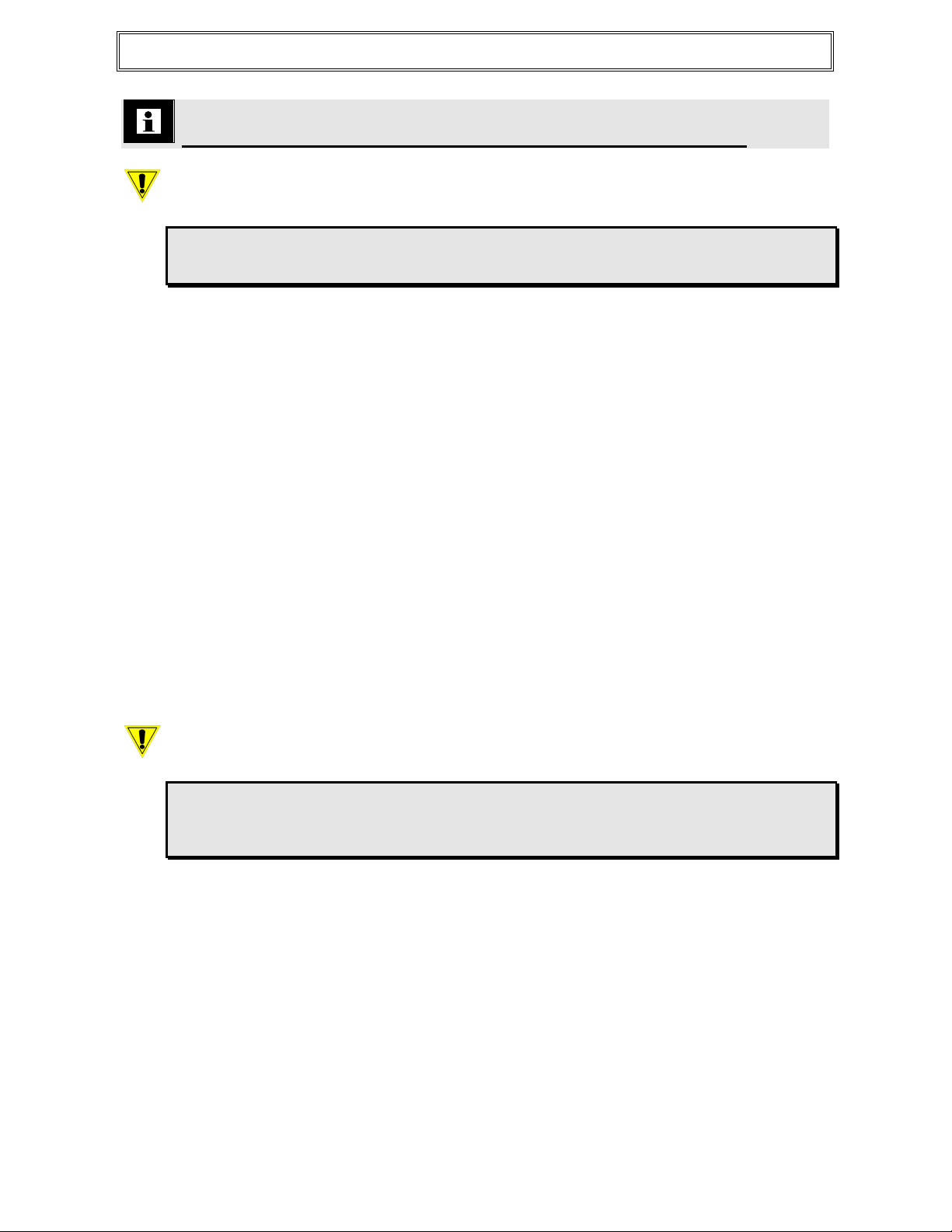
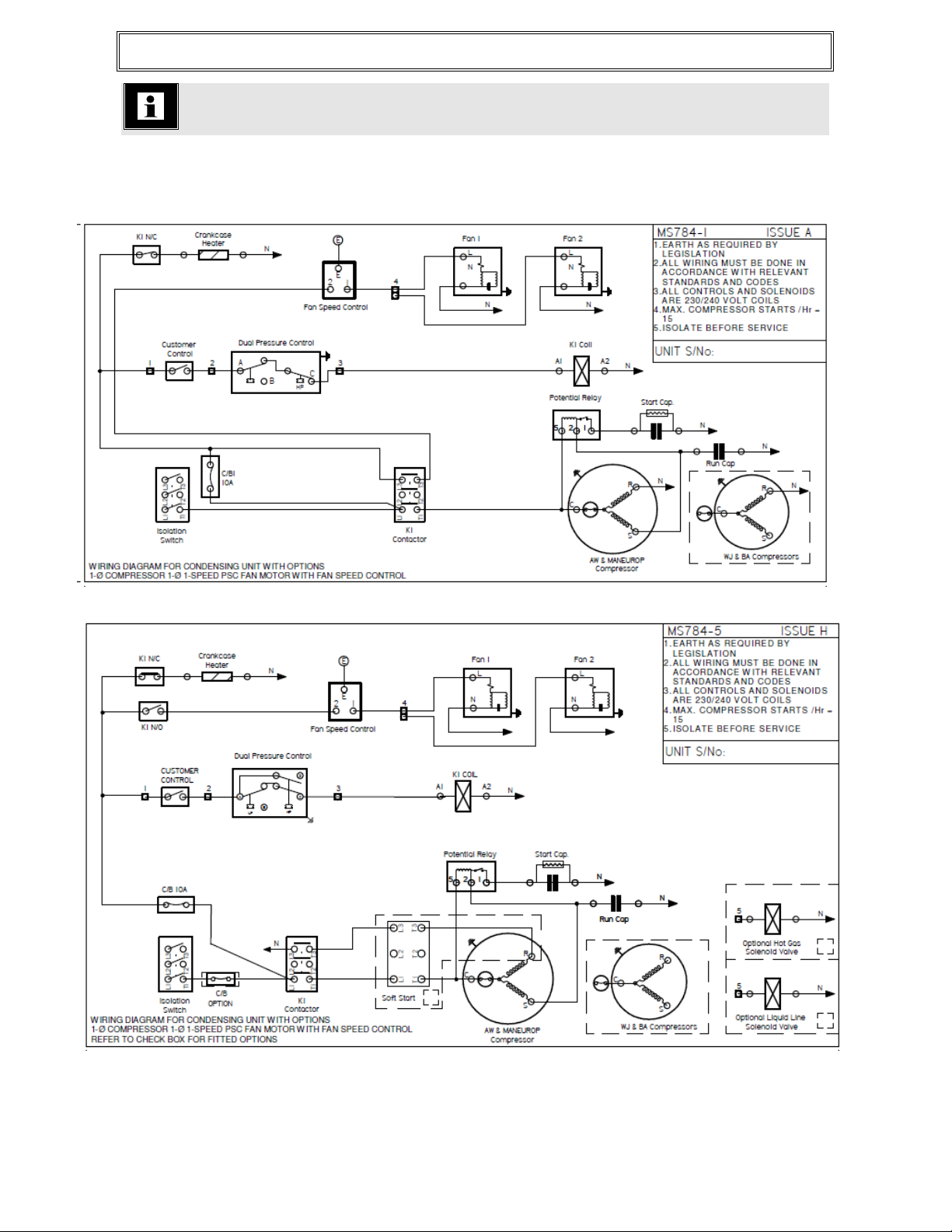
Standard wiring schematics
MS784-1 POLAR PACK 1 PH AW / WJ/ BA / MANEUROP COMPRESSOR AND 1 PH PSC FAN MOTOR
WITH FSC
MS784-5 POLAR PACK 1 PH COMPRSR AND 1 PH PSC FAN MOTOR WITH FSC AND OPTIONS

Document No.: CL232 issue F
Page No. 13 of 15
MS784-6 POLAR PACK 3 PHASE COMPRSR AND 1 PH PSC FAN MOTOR WITH FSC AND OPTIONS
MS784-7 POLAR PACK 1 PH DORIN COMPRSR AND 1 PH PSC FAN MOTOR WITH FSC AND OPTIONS

Document No.: CL232 issue F
Page No. 14 of 15
MS784-8 POLAR PACK 3 PH DORIN CMPRSR AND 1 PH PSC FAN MOTOR WITH FSC AND OPTIONS

Document No.: CL232 issue F
Page No. 15 of 15
COMMISSIONING NOTES
UNIT SERIAL NUMBER
UNIT INSTALLATION/COMMISSIONING DATES
286 HORSLEY ROAD MILPERRA NSW 2214
LOCKED BAG 6501 REGENTS PARK NSW 2143
A.B.N.67 000 056 717
HEATCRAFT AUSTRALIA PTY LTD
Table of contents
Other Heatcraft Industrial Equipment manuals


