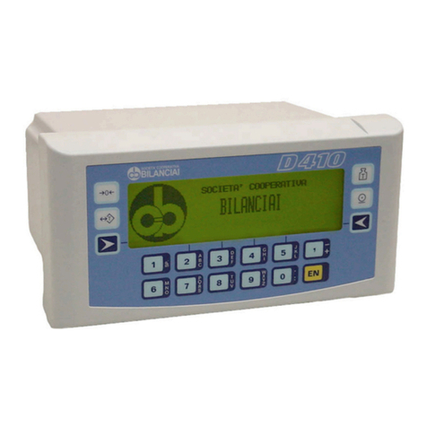
Heath Company Heathkit H9 User manual

,,'"..'t'. '
::, .:.,r .
H
MANUAL
for the
VIDEO
TERMINAL
Model
H9
ASSEMBLY 5e5-1se6-05
\,
\
HEATH
COMPANY
. BENTON
HARBOR,
MICHIGAN

HEATH
COMPANYPHONEDIRECTORY
Thefollowing
telephonenumbers
aredirectlines
tothe
departmentslisted:
Kit
orders
anddeliveryinformation ...... (616)
982-3411
Credit. ......(616)982-3561
ReplacementParts.. .. (616)
982-9571
TechnicalAsslstance
Phone Numbers
8:00A.M.to 12
P.M.and 1:00
P.M.to 4:30P.M., EST,Weekdays
Only
RZC,Audio,
andElectronic
Organs. .... (616)
982-3310
Amateur
Radio
TestEquipment,
WeatherInstruments
and
Home
Clocks
Television
Aircraft,
Marine,Security,
Scanners,Automotive,
Appliances
andGeneralProducts .... . (616)
982-3496
Computers ... (616)
982-3309
YOUR HEATHKIT 90 DAY LIMITED WARRANTY
If you ae not satisfied with our sewice - warranty or otherwise - or with our products, write directly to our Director of Custoner
Services,Heath Company, Benton Harbor, Michigan 49022.He will make certain your problems receive immediate, personal
attention.
Our attorney, who happens to be quite akitbuilder himself, insists that we describe our warranty using all the necessary legal
phrases in order to comply with the new wananty regulations. Fine. Here they are:
For a period of ninety [90) days after purchase, Heath Company will replace or repair free of chmge any parts that are defective
either in materials or workmanship. You can obtain parts directly from Heath Companyby miting us at the addressbelow orby
telephoning us at [616] SB2-3571.And we'll pay shipping chmges to get those parts to you - anywhere in the world.
We wmrant that during the first ninety (90) days after purchase, our products, when correctly assembled, calibrated, adiusted
and used in accordance with our printed instructions, will meet published specifications.
If a defective part or error in design has caused your Heathkit product to malfunction during the wailanty period through no
fault of yours, we will service it free upon proof of purchase and delivery at your expense to the Heath factory, any Heathkit
Electronic Center (units of Schlumberger Products Corporation), or any of our authorized overseasdistributors.
You will receive free consultation on any problem you might encounter in the assembly or use of your Heathkit product. |ust
drop us a line or give us a call. Sorry, we cannot accept collect calls.
Our wananty does not cover and we ile not responsible for damage caused by the use of corrosive solder, defective tools,
incomect assembly, misuse, fire, or by unauthorized modifications to or uses of our products for purposes other than as
advertised. Our warranty does not include reimbursement for customer assembly or set-up time.
This warranty covers only Heathkit products and is not extended to allied equipment or components used in conjunction with
our products. We are not responsible for incidental or consequential darnages. Some states do not allow the exclusion or
limitation of incidental or consequential damages, so the above limitation or exclusion may not apply to you. This waranty
gives you specific legal rights, and you may also have other rights which vary from state to state.
HEATH
COMPANY
BENTONHARBOR,MI.49022
(616)
982-3296
(616)
e82-3315
(616)
982-3307
d5
o<J
-ir
.fJ
=-
Prices
andspecifications
subjectto changewithoutnotice. ffirdtffbTbTbllThtllK

Heathkit@
Manual
for the
VIDEOTERMINAL
ModelH9
ASSEMBLY 5e5-1ee6-05
HEATH COMPANY
BENTON HARBOR, MICHIGAN
Copyrlght@ 1977
HeathCompany
Nl RightsReserved
Printed
inthe
UniledStatesofAmerica
49o 22

Pase. @
TABLE OF CONTENTS
INTRODUCTION.
UNPACKING
.. ..
CHASSIS
Partslist .....5
Assembly
Notes ... .. 8
Step-by-StepAssembly ...71,
POWER
SUPPLY
CIRCUIT
BOARD
PartsList
Assembly
Notes .
Step-by-StepAssembly
PowerSupply Checkout
CHARACTERGENERATOR
CIRCUIT
BOARD
Parts
List
Step-by-StepAssembly
CharacterGeneratorCircuit
BoardCheckout
VIDEOCIRCUIT
BOARD
Parts
List
Step-by-Step
Assembly
Video Circuit BoardCheckout
CRTInstallation.
KEYBOARD
CIRCUIT
BOARD
Partslist ....85
Step-by-StepAssembly ... 87
Keyboard
Circuit
Board
Checkout ..... 99
RAM AND COUNTERCIRCUIT
BOARD
Partslist ...103
Step-by-StepAssembly .. 105
Ramand CounterCircuit
Board
Checkout .. 1.12
INPUT/OUTPUT
CIRCUIT
BOARD
Partslist ...1.17
Step-by-StepAssembly ..119
I/OCircuitBoard
Checkout .. .. 728
TIMING AND PROCESSING
UNIT
CIRCUIT
BOARD
Partslist ...732
TPUCircuit
Board
Checkout ... 734
ADIUSTMENTS. ... 't37
FINAL
ASSEMBLY ....... 139
33
36
38
46
52
54
61
62
64
73
75 CUSTOMERSERVICE .... Insiderear
cover
WARRANTY
.... .. Insidefront
cover

-
Page3
L@
INTRODUCTION
The Heathkit Model H9 Video Terminal can display
information coming from a computer or enter infor-
mation into acomputer. The information is displayed
ort a 72" (diagonal) cathode ray tube (CRT) which is
capableof displaying 960charactersatone
time in 12
rows with 80 characters per row.
A sixty-seven key ASCII keyboard permits you to
composeand edit directly onto the CRT with a capa-
bility of 64 different characters and 24 different func-
tions. This messageor program canthen betransmit-
ted through the standard serial I/O interface [EIA,
TTL, or 20 mA current loop) to a digital computer or
through the parallel I/O interface to a paper tape
punch.
The Video Terminal can be used with any digital
computer in dedicated, stand-aloneapplications, or
in time-sharing systems. It lets you communicate
with a digital computer in higher-level languages,
such as Basic, Assembler, etc., rather than in just
machine language.The Video Terminal is also
much
faster (up to 9600 baud) than the standard electro-
mechanical teleprinter systems. You can select any
data rate between 110 and 9600 baud.
Other important features include:
o Automatic scrolling.
a Cursor controls.
o Erase
to end of line.
. Erase
page.
o Short form (four 12-line columns of 2O
characters).
o Automatic line carryover.
o Plot mode.
o Built-in speaker
(audible bellJ.
These features, along with the attractively-styled
cabinet, make the Video Terminal a very versatile
peripheral to your computer system.

TJNPACKING
Inside the shipping carton there is a box stamped
"PKS 1-6," and a numberof loose
parts.
After you
remove
theboxstampedPKS1-6, all theremaining
parts
will beconsideredthe"final pack."
The
cathode
ray tube is separate
in its own shipping carton.
Remove
the box stamped
PKS 1-6- Remove
the
cathoderay tube carton and set it asideuntil it is
calledfor in aPartsList.WARNING:
Donot openthe
cathode
raytubecarton
until you areinstructed
to do
soin a step.Improper
unpacking
canresult
in per-
sonalinjury or tube damage.
Whenyou openthebox stampedPKS1-6, you will
find a PackIndex Sheet
in the top of the box. This
sheetshows
howthe
boxhas
been
divided into differ-
entcompartments
which arereferredtoin theManual
as"packs."Youwill bedirected
toopeneach
ofthese
"packs" asit is needed.
CAUTION: No partsshould
be removed from the boxes or their compartments
until theyarespecificallycalledforby aPartsList in
the Manual.
Each
assembly
section
oftheManualcontains
itsown
"Parts List" and "Step-by-Step
Assembly" instruc-
tions.
At thebeginning
ofeach
"Parts
List,"you will
beinstructed
to open
oneof the packs.
You will also
be directed,in somePartsLists, to remove certain
parts
from the final pack.

-
Page5
r@
CHASSIS
PARTSLIST
Unpack the following parts from the final pack and
checkeach
partagainst
thefollowing PartsList.The
keynumbers
correspond
tothenumbers
ontheChas-
sisParts
Pictorial
(Illustration
Booklet,
Pages1and2).
Any partthat is packaged
in anindividual envelope
with apart
numberonit should
be
placed
backin the
envelope
afterit isidentified until it is called
forin a
step.
NOTE:
You shouldplace
theparts
in alocation
other
thanyour work area.
Many of these
parts
will not be
useduntil later in the assembly
and will be in your
way if placedon your work area.
Some
parts
aremarkedwith a"77L-"or"172-"pack-
agingnumber.These
numbersare
usedfor packaging
only anddonotappear
in theManualPartsList.Save
all packagingmaterial until all partshavebeenlo-
cated.
To order a replacement part, always include the
PART
NUMBER.
UsetheParts
Order
Formfurnished
with this kit or at the rearof this Manual. If a Parts
Order Form is not available,referto "Replacement
Parts"insidetherear
cover.
Your Warranty
is inside
thefrontcover.For
prices,
refer
totheseparate
"Heath
PartsPriceList."
Each
circuit componentin this kit hasaCircuit Com-
ponent
Number
(R2,
C4,
Q1,etc.).This is a specific
number
for onlythatone
partin thekit. Thepurpose
ofthese
numbers,
which are
especially
usefulif apart
everhasto bereplaced,
isto help you easilyidentify
the same
part in eachsectionof the Manual. These
numbers
will appeal
In the Parts
List.
At the
beginningofeach
stepwhere
acom-
ponentis installed.
In someillustrations.
In the Schematic.
In the sectionsat the rearof the Manual.
IMPORTANT:TheTPUcircuit boardassemblyhasbeenwired andtestedatHeath
Company.
If it malfunctions
during the90-day
period,
returnthecompletecircuitboardassemblytoHeath
CompanyoraHeathkitElectronic
Center.It will be promptly repaired and returned. Individual replacement parts are not supplied under
warranty. DONOT attempt
to servicethis circuit boardassembly
yourself
during thewarrantyperiod;
todo so
voids the warranty.

KEY
No. HEATH QTY.
DESCRIPTION
PartNo.
CIRCUIT
COMPONENTS
CIRCUIT
Comp.No.
c1
T2
T1
L1
D2
D1
SW1,SW2
SPKRl
A1 6470-12
A1 6-15'l
A2 2't-96
M 21-17
A3 25-810
A4 25-156
A5 25-822
A6 51-194
A7 g-943
A8 58-8
A9 56-26
A9 56-56
A10 60-2
All 401-163
A13 417-894
414 421-23
INSULATORS
81 73-92
82 73-132
73-23
83 75-30
84 75-52
85 75-728
86 75-734
75-124
87 75-704
47 A, 1|4-watl(yellow-
violet-black)resistor
150
O, 1/2-waft
(brown-
green-brown)
resistor
36 pFceramiccapacitor
270 pF ceramiccapacitor
500pF electrolytic
capacitor
4000pF electrolytic
capacitor
12,@O
y"F
electrolytic
capacitor
Flyback
transformer
Powertransformer
Deflection
yoke
1N191
diode
(brown-
white-brown)
1N4149diode
Slideswitch
Speaker
1 BU180A
transistor 01
1 l-ampere,3AG,
slow- Fl
blowfuse
1 314'
x 5"foam
tape
1 Small
rubber
grommet
1 Largerubber
grommel
1 Line
cordstrainrelief
'l Slideswitchinsulator
'12 Circuitboardstandoff
4 Circuitboardholder
1 4-112'
x d'fish
paper
1 Transistorinsulator
R'l
c5
@
c3
c2
1
1
1
1
'l
1
1
1
2
1
WARNING:Donotremovethecathoderaytube
fromits
cartonuntilyou areinstructed
to do so in a step.
A1z 411-830 1 310GJB4
cathoderay
tube CRTl
NOTE:Atransistorcanbemarkedforidentificationinoneof
thefollowing
fourways:
1. Partnumber.
2. Typenumber.
3. Partnumber
andtypenumber.
4. Part
numberwith
a
typenumber
otherthanthe
one
listed.
Paseo @
KEY HEATH QTY.
DESCRIPTION
No. Part
No.
CONNECTORS
_ SHELLS
- PLUGS
CIRCUIT
Comp.No.
HARDWARE
NOTE:
The
hardware
may
be
packed
in
morethan
one
packet.
Open
allthehardware
packets
(marked
HDW)
before
you
check
thehardware
against
theParts
Ltst.
#4 Hardware
c1 432-866 15
c2 432-753 15
c3 432-855 38
u 432-9il 1
c5 432-970 2
c6 432-821 1
c7 432-183 1
c9 432-924 |
c10 432-951 1
c1l 432-832 13
D1 250-213 1
D2 252-2 3
D3 2U-9 4
D4 253-703 1
#6 Hardware
D5 250-4s2 16
D6 250-381 I
D7 250-1264 10
D8 250-89 10
D9 2fi-475 6
D10 2fi-162 1
D11 250-569 6
D12 250-13 4
D13 252-3 16
D14 252-22 4
D15 252-708 2
D16 252-195 16
D17 253-60 2
D18 2*-1 16
D19 259-1 12
#8 Hardware
D20 250-137 4
D21 250-585 4
D22 2524 8
D23 2V-2 6
D24 2*-28 6
Smallspringconnector
Largespringconnector
Female
connector
4-conneclor
socketshell
s-connector
socketshell
6-connector
socketshell
g-connector
socketshell
24-connector
socketshell
4-pin
plug
6-pin
plug
12-pin
plug
4-40
x 5/16'screw
440 nut
#4 lockwasher
Plastic
shciulder
washer
6-32
x 114'
blackscrew
6-32
x 3/8'blackscrew
6-32
x 3/8'hexhead
screw
6-32
x 3/8'screw
6-32
x 318'
hex
head
self-tappingscrew
6-32
x 1/Z screw
6-32
x 3l4i blackscrew
6-32
x 1"
screw
5-32nut
#6 square
push-on
nut
#6 round
push-on
nut
6-32self-retainingnut
#6 flatwasher
#6 lockwasher
#6 solder
lug
8-32
x 3/8"screw
8-32
x 1/2'screw
8-32nut
#8 internal
toothlockwasher
#8 externaUinternaltooth
lockwasher
#8 solderlug
D25 259-2

KEY
No. HEATH QTY.
DESCRIPTION
PartNo.
LINE
CORD
- HARNESSES
- WIRE
-
CABLE- SLEEVING
CIRCUIT
Comp.
No.
89-54 1
134-1001 1
134-1002 1
134-1009 1
134-1016 1
340-8 10',
344-15 z',
344-59 10',
344-94 3g'
347-1 8',
346-1 12',
METALPARTS
E1 204-2325 2
E2 204-135 2
E3 206-1247 1
E4 206-1248 1
E5 203-1886-1 |
E6 204-2324 1
E7 207-86 1
E8 207-63 1
E9 200-1321 1
E10 203-1887-1 1
E11 203-1885-1 1
MISCELLANEOUS
Linecord
Mainharness
Busharness
2'l
-wire
cable
assembly
8-wire
cable
assembly
Barewire
Blackwire
Whitewire
Yellow
wire
8-wirecable
Sleeving
CRT brace
Anglebracket
Highvoltagetopshield
Highvoltagebottomshield
Rear
panel
CRT bracket
Capacitorclamp
Capacitorstrap
Chassis
Frontpanel
Bottompanel
Rollmaskingtape
Cabinetshell
Assembledtimingand
processing
unit
(TPU)
circuitboard
F1 74-6
90-'t2't0-1
181-2679-2
I
1
1
KEYHEATH OTY.DESCRIPTION
No. Part
No.
Miscellaneous
(cont'd.)
CIRCUIT
Comp.
No.
F2 260-16
203-1894
F3
F4
F5 205-778
F6 258-33
F7 258'79
F8 261-21
F9 352-13
F10 3y-7
390-147
390-1382
F11 390-1387
F12 391-61
1
F13 423jt1
F14 431-604
F15 431-42
446-686
406-664
Fl6 490-5
490-1
85
F17 490-189
Fl8 490-168
391-34
597-260
4
1
1
't
2
6
4
1
6
1
2
'l
1
1
1
I
1
1
1
'1
1
1
1
1
1
1
Alligator
clip
Cabinet
side panel
set consistingof:
Leftside (#203-1889)
Rightside
(#203-1890)
Screwdriver
blade
Coil
spring
Tensionspring
Rubber
foot
Silicone
grease
Cabletie
High
voltage
label
Chassis
plug
label
Modellabel
Modellabelholder
Fuseholder
3-lug
terminalstrip
s-lugterminalstrip
Cabinetwindow
Magnitying
glass
Plasticnut starter
De-solderwick
(braid)
Integratedcircuit
(lC)puller
Wrench
Blueandwhite
label
PartsOrderForm
Solder
Manual
(See
Page1
for part
number.)
lllustration
Booklet
Operation
Manual
(See
Page1forpart
number.)

Pases @
ASSEMBLYNOTES
TOOLS
Youwill needthesetoolstoassemble
vour
kit.
LONG.NOSE
PLITR
S
I
I
I
DIAGONAT
CUTTTRS
I
I
I
PLIERS
WIRT
STRIPPIRS I
4''-BLADT
DRIVTRS
@
l
l/8"&r/4'
SCRTWD
OTHER HELPFUL --+.
root,s 4 \ )
\, DiSOLDTRING
EIJLBT
! ilur
sTARTtR
1{MAY
Bt SUPPtItD
I WIIH KIT}
*I0 RtM0vt s0LDtR
FR0M
ctRcutT c0NNEcTt0NSI
-----J
ASSEMBLY
Follow the instructions
carefullyandreadthe
entirestepbefore
you performthe operation.
The illustrations in the Manual are called
Pictorials
and
Details.Pictorials
show
the
over-
all operation for a group of assembly
steps;
Details
generally
illustrateasingle
step.When
you aredirectedto referto a certainPictorial
"for thefollowingsteps,"continue
using
that
Pictorialuntil youarereferredtoanotherPicto-
rial for another
Sroupof steps.
3.1,
2.
4.
J.
Mostkits useaseparate
"Illustration Booklet"
that containsillustrations (Pictorials,
Details,
etc.)
thataretoolargefortheAssemblyManual.
Keepthe "Illustration Booklet" with the As-
semblyManual.The illustrations in it arear-
rangedin Pictorialnumbersequence.
Positionall parts
asshown in the Pictorials.
Solderapartora
groupofparts
onlywhenyou
areinstructed
to do so.
PHILLIPS
SCREWDRIVTR
PtNC
tr
SOTDERING
IRON
125
10 40 wATTS)

-
Page9
r@
Eachcircuit part
in anelectronic
kit has
itsown
component number (R2,C4, etc.).Use these
numbers when you want to identify the same
part in the various sectionsof the Manual.
Thesenumbers,which areespecially
usefulif a
part hasto bereplaced,appear:
In the Parts
List,
At the beginning of each step where a
component
is installed,
In someillustrations.
In the Schematic,
In the sectionat the rearof the Manual.
Whenyou areinstructedto cut somethingtoa
particular length, usethe scales
(rulers)pro-
vided at the bottom of the Manual pages.
SAFETY WARNING: Avoid eyeiniury when you cut
off excess
lead lengths.Hold the leadssothey cannot
fly toward your eyes.
6, SOLDERING
Soldering
isoneof
the
mostimportantoperations
you
will perform
while assembling
yourkit. A good
sol-
derconnection
will formanelectrical
connection
be-
tween two parts,such as a component lead and a
terminal strip lug. A bad solder connection could
prevent
anotherwise
well-assembledkit fromoperat-
ing properly.
It is easyto make a good solderconnectionif you
follow afew simplerules:
1. Usethe right type of soldering iron. A 25 to
40-watt pencil soldering iron with a 1/8" or
3/16"chiselor pyramid tip works best.
2. Keepthesoldering
irontip clean.Wipe it often
on awet spongeor cloth; thenapply solderto
the tip to give the entire tip a wet look. This
process
iscalledtinning, andit will protect
the
tip and enable
you to makegood connections.
When
soldertendsto"ball" ordoesnotetick
to
the tip, the tip needsto be cleanedand retin-
ned.
7.

Paselo @
A GOODSOLDER
CONNECTION
SOtDER
FLOWS
OUIWARD
AND GRADUALLY
BLENDS
WITH THTWIRI AND LUG. SOLDERING
IRON
POSITIONiD
CORRTCILY
,ur/
When
boththewire
andthelug
are
heated
atthesame
time,
thesolderwillflow
onto
the
wireandthelug
evenly.
Thesolderwillmake
a goodelectricalconnection
be-
tween
thewire
and
thelug.
Solder each connection as follows:
1. Pushthe soldering
iron
tipagainst
thewireand
thelug.
Heat
both
the
wireandtheluglortwoor
three
seconds. SOTDERING
IRON
2. Apply
soldertothe
wire
andthelug,
nottothe
solderingiron.
IMPORTANT:
Let
theheat
ofthe
wireandlugmelt
thesolder.
3. As thesolderbeginsto melt,
allowit to flow
around
the
connection.Thenremove
thesolder
andtheiron
and
let
the
connectioncool.
SOLDtRING
POOR
SOLDER
CONNECTIONS
SOTDER
DOTSNOI FLOW
LUG
ANOWIRT. A DARKoNTorHe
ROSIN
BEADSURROUNDS
AND
TATIS THt WIRI FROM INSUROSIN
THI CONNECTION
SOLDERING
IRON
POSITIONED
wlRE
iuConnEcriv
Whenthewireisnotheated
sufficiently,thesolderwill
not flow onto the wire as shown above.
To correct,
reheat
the
connectionand,ifnecessary,
applya small
amount
ofadditionalsolderto
obtaina
good
connection.
SOtDIR
INWARD
OF
LUG.
APPTARS
AND SIT IO FLOW
ONTOP
ROSIN s0tD
IRONR
ING
POSITIONED
INCORRECTLY
When
thelugisnotheated
sufficiently,thesolderwill
blob
on
thelug
asshownabove.To correct,
reheat
the
connectionand,ifnecessary,
applya smallamount
of
additional
solder
to obtaina goodconnection.

@ t"n"tt
STEP.BY.STEP
ASSEMBLY
NUT
DRIVER
ll o*
pusH
oowni
? ,r*$'Jl,(,*
/
@o iz
r'rur
druu LocKWAsHER
Detail t-tB
NOTE: Use the nut starter furnished with the kit to
pick up and start4-40 and 6-32 nuts on screws.
The
wrench supplied can be used to tighten hex head
screwsand nuts in hard-to-reachplaces.
( ,/) Refer
toDetail 1-18 and mount a 5-lug terminal
strip at AR. Use a 6-32 x 318' screw, two #6
lockwashers,
and a6-32nut. Besureto position
alockwasher on eachside of the mounting foot.
NOTE: Do not use the black or hex head
hardwareunlessit is specifically called for in a
step.
(i" ) Mount a #6 solder lug atAT with a 6-32 x 3lB"
screw,and a6-32nut. Position the solderlug as
shown.
STANDOFF
INSULATOR
CARTFULLY
WORK
INSULATOR
INTO
HOLE
Detail 1-1A
Refer
toPictorial 1-1
(IllustrationBooklet,Page
3)
for
the following steps.
(rA Position
thechassisbottom-side
up asshown.
(A Installasmall
rubbergrommet
in thechassisat
holeAA.
( rf) Placeall ofthe circuit boardstandoffsin warm
water and soakthem for 3 to 5 minutes.
( I ) Refer
to Detail1-1Aand install acircuit board
'' standoffat AB in the chassis.
( U Install circuit boardstandoffs
in the chassis
at
AC,AD,AG,
AH,AJ,AK, AM, AN, andAP.

Refer
to Pictorial1-2
(IllustrationBooklet,
Page
4)for
the following steps.
f fJ Turn thechassis
overandpositionit as
shown.
(r"
) Makealineacrossthechassis4-511,6'fromthe
backlip asshown.
(', ) On this line, make
amark 1"from the left side
andasecondmark
3-1,14'infromtheleft
sideof
thechassis.
(U) On
this
same
line,
make
a
mark1"from
theright
side
andasecondmark3-1/4"in fromtherieht
side
ofthechassis.
(
\/) Locate
a circuit boardholderandremove
the
protectivepaper
backing.
(;, ) Referto Detail1-2Aandpress
thecircuit board
holderontothechassis
at
P.
Makesuretheslot
in theholderisdirectly overtheline across
the
chassisandtheedgeofthe holderis onthe 1."
mark nearestthe left edgeof the chassis.
CIRCUIT BOARD
HOLDER
( 4 In thesamemanner,
press
circuit boardholders
to the chassis
at Q, at R, and at S.
( 4 Install circuit boardstandoffsat AE and AF
from the undersideof the chassis.
( ,) Mount two #6 solder
lugsatBE/BF
with a6-32
x 3/8"
screwanda
6-32nut. Position
thesolder
lugs
as
shown.
(,/) Mount
two#6 solderlugs
at
BG/BH
with a6-32
' x 3/8'screw anda6-32nut.
('l Mounttwo #6 solderlugs
atBI/gf with a6-32
x 318"
screwanda6-32nut.
( d' Mounttwo#6 solderlugsatBM/BNwitha6-32
x 318"
screwanda6-32nut.
( 4 Refer
to Detail1-28and cut eachleadof the
powertransformer
to its specifiedlength.Mea-
surethe leadsfrom wheretheycome
out ofthe
transformer.
Thenremove
theindicatedlength
of insulation from the end of eachwire.
|14" 3-rl2',
/"[r3^'
Ll4"
MEASURE
FROMHERE
Detail1-28
5
5
-112',
RID GRN
RTD ORG
6RN 0RG 4_rlT,
BLK-RED
BLK-YEL
l-
nr
Nt[.-/
Detail 1-2A

S
IX CONNECTOR
SOCKTT
RED
LARGISPRING
CONNECTOR
INSET
CRIMP OVERBARE
TND
OFLEAD
AND
StOTS
INSULATION
Detailr-2C
( 1 Refer
toDetail1-2Cand
crimpandsolderalarge
spring connectoronto one of the greenpower
transformer
leads.NOTE:
Besurethatyou do
not solderthe spring
part 9f theconnector
so
that it cannot move.
( Vl Check
yoursolder
connectiontomakesurethat
theconnectionissolid.
The
connection
should
have
asmooth,
shinyappearance.Iftheconnec-
tion is dull or grainy, reheat
the connection.
tyl CrimpandsolderIarge
spring
connectorsonto
theother
green,
bothorange,andbothredtrans-
former leads.
( ,,4 Locate
the6-connectorsocket
shellandnotethe
numbers 1 and 6 stampedin the front of the
shell.This indicates
holes1 and 6.
Detail 1-2D
NOTE: If it is evernecessaryto remove a spring con-
nector from the socketshell, usea small screwdriver
and depressthe tab on the spring connector through
the slotin the connectorshell while you pull thewire
out. SeeDetail 1-2D.
( 4 Refer again to Detail 1-2C and insert the large
spring connnector on one of the green trans-
former leads
into hole 1 on the socket
shell. Be
sureto position the spring part away from the
slottedsideofthesocket
shell.Pushin until you
hear the connector snap into the shell.
Install the other transformer leads into the socket
shell in the samemanner as follows:
( ,) Other
greenlead
into hole2.
( i.l Either
orangeleadinto hole3.
( ,) Otherorangelead
into hole
4.
( ;) Either red lead into hole 5.
( \ Other red lead into hole 6.
SOLDER ENDOF
\ INSULATION
@:_
AFTER
CLIP HAS
COOLED,
BEND
OVIR
PUSH
IN ON
TABOF
SPRINGCLIP
'BEE

Page 14
K;fi
^M
8-32
x 318"
SCREW
6-32
x ll4"
BLACK
SCREW
Detail 1-3A
.t
o
Detail 1-28
(/) T1:
Refer
toDetail1-2E
andinsert
theother
four
power transformer leads down through grom_
met AA. Then mount the power transformerto
the chassis
with four g-32 x 3/g,,
screws,
four
#B lockwashers,
andfour g-32
nuts.Move the
transformer away from the rear panel asfar as
the mounting holeswill permit. Then tighten
the hardware.
@)a-lzNur
Set
the chassis
aside
temporarily.
Refer
toPictorial1-3(IllustrationBooklet,
page
4)for
the following steps.
( I Locate
therearpanel
andpositionit as
shown.
14f SWz:
Refer
to Detail 1-3A and install a 6-lug
slide switch SW2with two 6-32 x 1/4"black
screws.
h,4 SW1:
Install
a 6-lugslideswitch at SW1.
Use
only two 6-32 x 1/+"
black screws.
( ) F1: Referto Detail 1-3B and install the fuse-
holderatF1.
Use
thehardware
thatis supplied
with the fuseholder.Be sure to position the
fuseholder
lugsas
shown.NOTE:
Donot over_
tighten the hardware or the fuseholder mav
break.
6r(cv)z
(rNcHES)
%
3/A I3/t 1
7lA

@ t"n"tu
NUT
RUBBTR
WASHER
Detail 1-38
{ Xefer to Detail 1-3C and bend lug 1 of the
fuseholder
out slightly. Becarefulthatyou do
notapply
pressure
tothelugwhere
it comesout
of the fuseholder.
REIVIOVE
4" OFOUTER
I
IHAI YOU
DO
NOT
CUT
INNERLEADS.
NSULATION. BE CARFFL-
IHE INSULATI ON OF IHE
LUG
I
BEND
.IGHTLY
CUTIHT LEADS
TOTHEINDICAIEDLENGTHS
AND
RTMOVEI/4" INSULATION
FROM
THEENDOF
TACHLFA
D.
FINT
WIRE
STRAND
S
3, TW
I
STTHE
FI
NEW
I
RESTRANDS
ATTHETND
OF
EACHLEAD
AND
MFLTA VERY
SMAL!.
AMOUNT
OFSOTDER
TOTHFSTRA
NDSTOHOLD THEM
TOGETHER.
Detail 1-3D
(4 Refer
to Detail1-3D
andprepare
the end of the
line cordasshown.
(..1 RefertoDetail1-3Eandinstallthestrainrelief
onthelinecordwheretheouter
insulationbe-
gins.Then install the strainrelief into hole CB
from the backof the rearpanel.
PLACT
THT
LINE SQUEEZE
THETWO INSERTTHE
REAR
CORD
IN THE
SLOT, SEGMENTS
TOGETHER. HALFINTO
THE
HOLE.
NOT
I TH
IS
TOBEND
Detail t-eC Detail L-3E

RefertoPictorial1-4
(IllustrationBooklet,
Page
4)for
the following steps.
( ,4 Mount the rear panel to the chassiswith two
6-32 x 1/4"black screws.
Do not install any
screws
in thetwo holes
nearthelargecutoutin
the rearpanel.
( I Referto insetdrawing #1.on Pictorial 1-4and
place
theslideswitchinsulatorover
thelugsof
switchSW1.
NOTE:Whenyou areinstructed
to prepare
stranded
wire asin the nextstep,cut the wire to the length
indicated and remove 714'of insulation from each
end.
Thentwistthe
finewire strandsat
theends
of
the
wireandmeltasmall
amountofsoldertothestrands
to hold the strands
together.
( ) Prepare
the following black strandedwires.
2_\14'
4"
NOTES:
1,. When you areinstructed to make a mechani-
callysecure
connection
as
inthe
nextstep,
form
a
hookin theendof
thewireand
insertthe
wire
throughthelug.Thencrimp the
hooksecurely
tothe
lug.
See
insetdrawing#2 on
Pictorialt-4.
2. Inthefollowingsteps,
(NS)
means
nottosolder
the connection
becauseother wires will be
added
later.
{S-),
with a number
suchas
(S-3),
meansto solderthe connections.The number
following the "S" tells how many wires areat
the connection.
( '/) Connect a 2-114x
black stranded wire from
switchSW1lug 5 (S-1)
to fuseholderF1lug 1
(S-1).
Makemechanically
secureconnections.
( t/) Connect
the
4"
blackstrandedwire from switch
SW1lug4(S-1)
toterminalstripARlug r (NS).
Makemechanically
secureconnections.
( ) Connectthe black lead from the line cord to
fuseholder
F1lug2(S-1).
Make
a
mechanically
secureconnection.
(, ') Connectthe green
leadfrom the line cord to
solder
lug AT (S-1).
Makea mechanically
se-
cureconnection.
(r,/) Connectthe white lead from the line cord to
terminal
stripAR,lug 5(NS).
Makeamechani-
callysecure
connection.
Connect
thepower
transformer
leads
toterminalstrip
ARin thefollowing steps.
Makemechanically
secure
connections.
(r ) Black-red
lead
tolug 1(NS).
( , ) Black-yellow
lead
to lug 2 (NS).
( rJ Black-green
lead
to lug a (NS).
(' ) Blacklead
tolug s (NS).

NOTE:Two sets
of line voltagewiring instructions
follow; one
for 120VAC line voltage,
andone
for 240
VAC
linevoltage.In
theU.S.A.,120VACis
mostoften
used,
while in othercountries24OVACis
morecom-
monly used.USEONLYTHEINSTRUCTIONS
THAT
AGREE
WITHTHE
LINEVOLTAGEINYOURAREA.
120VAC WIRING
Detail r-+A
Referto Detail1-4Afor thefollowing steps.
( "f Prepare
two 1,-314"blackstrandedwires.
(A Connect
a 1.-314"blackstrandedwire to termi-
nal strip AR betweenlugs 1 (S-3)
and 2 (S-2).
Make these
connections
mechanicallysecure.
( J' Connecta 7-314'black
strandedwire to termi-
nal stripAR betweenlugs4 (S-2)
and5 (S-3).
Make mechanicallysecureconnections.
( ,,)' Remove
the red cap from the fuseholderand
insert the 1-ampereslow-blow fuse.Then re-
placethe capinto the fuseholder.
24O
VAC WIRING
24oVA,CW|RING
Detail 1-48
Refer to Detail 1-48 for the following steps.
t ) Prepare a 2" black stranded wire.
f ) Connect
this2"blackstrandedwire toterminal
strip
ARbetweenlugs
2(S-2)
and
a(S-2).
Make
mechanically
secure
connections.
( ) Solder
lug 1 (S-2)
andlug 5 (S-2)
of terminal
strip AR.
( ) Removethe red cap from the fuseholderand
insert the 1/2-ampere slow-blow fuse (not
supplied). Then replace the cap into the
fuseholder.

PICTORIAL1.5
Refer
to Pictorial 1-5for the following steps.
( ) Setthechassisasidetemporarily.
NOTE;You may wish to placea soft cloth on your
work area
surfacefor theremainderofthekit assem-
bly. This will keep the side panels from getting
scratched.
( ' ) Locate
bothside
panels
andpositionthemona
softcloth.
( .l Referto the inset drawing and insert a self-
retaining nut into hole CB slotted end first.
Press
ortapthenut into theside
panel
until it is
flush with the surface.
t ) Turn a 6-32 x 3/8"hex head screwinto the
self-retainingnut to spreadthenut.Donotturn
the screwall the wav in. Then removethe
screw.
In thesamemanner,install self-retainingnutsin the
following holes.
CC
CD
CE
CF
CG
CH
cI ( )cN
cK ( )cP
CM
Table of contents

