Heath Zenith SO-4226 User manual

HEATH
l
/L
L
25
MHz
OSCILLOSCOPE
Model
SO-4226
595-3896
HEATH
COMPANY
Copyright
©
1987
Heath
Company
BENTON
HARBOR,
MICHIGAN
49022
All
Rights
Reserved
Page
2
Precautions
for
Use
Inspect
the
shipping
carton
for
serious
ship-
ping
damage.
If
you
notice
damage,
notify
the
carrier
immediately.
Before
you
apply
power
to
the
Oscilloscope,
make
certain
that
the
voltage
selector
plug
on
the
rear
panel
has
been
inserted
with
the
arrow
marking
in
the
direction
of
the
proper
line
voltage.
Also
check
the
fuse
to
be
sure
it
is
of
the
proper
rating.
Do
not
leave
a
bright
beam
on
the
CRT
screen
for
long
periods.
This
can
cause
permanent
damage
to
the
screen.
This
instrument
is
convection-cooled.
Always
be
sure
the
cooling
vents
are
not
blocked
when
you
are
operating
it.
To
insure
stable
operation
over
long
periods
of
time,
do
not
subject
the
Oscilloscope
to
vi-
bration,
direct
sunlight,
extreme
temperature
variations, high
humidity,
dust,
or
elec-
tromagnetic
fields.

Page
3
Table
of
Contents
INTRODUCTION
.
..ottt
einee
s
4
Horizontal/Time
Base
.
...................
18
CalIbTator
/o
PP
Rieniniis
s
i
s
v vavauns
19
BPECIFICATIONS
.
vovve
e
deaneti
Vo
Hlnmmne
5
CRT-Cant8l
.
o0l
%
vs
iy
s
vunnnn
19
Power:
Supply:
.
.
.
.
.inadalantlad
i
D
s
19
OPERATION
;5505455
sammmnanns
s §
s
¢
¥
prone
9
Controls
and
Connectors
..................
9
MAINTENANCE
&
ADJUSTMENTS
..........
20
Preliminary
Operation
...................
11
General
Maintenance
....................
20
Triggering
the
Sweep
...................
11
Adjustment
and
Calibration
..............
20
X-Y
Display
Operation
..................
12
Power
Supply
Adjustments
............
20
Voltage
Measurements
.
..................
12
CRT
Circuit
Adjustments
..............
21
Dual*Trace-Display
«¥%.
#8000
T
o
v
Vertical
Axis
Adjustments
.............
21
Synchronizing
TV
Signals
Horizontal
Axis
Adjustments
...........
23
Addition
and
Subtraction
Operation
.......
12
SCHEMATICS
..
..ttt
24
APPLICATIONS!
ccoesioisstimmnssssssas
13
Vertical
Amplifier
Schematic,
AC
Voltage
and
Frequency
Part
1
somonsssss
6000
ivvsasmmisistonsse
o o
o
o
o
25
Measurements
..
......oouerereenennn.n
13
Vertical
Amplifier
Schematic,
-
DC
Voltage
Measurement
................
13
Part
120
spouns
65
05
55
58§
&
Do
&
5
5
9
26
AM
Modulation
Measurement
............
14
Horizontal/Time
Base
Schematic,
Dual
Trace
Applications
.
.
.
.
.ovweisa
s
wns
14
PETE
1
ovnvasen
s
00
5% 55
85
8
50
BSQEEREESE
3
8
27
Comparison
of
Levels
«:::vvsmonmemiansens
14
Horizontal/Time
Base
Schematic,
Checking
Stereo
Systems
................
14
=75
2
R
28
SErvicing
TV
Sets
zisussssnssosmenutasss
14
Power
Supply
and
CAL
Schematic
........
29
Composite
Video
Analysis
...............
15
HV
Supply
and
CRT
Frequency
Measurement
With
Circuit
Schematici
.
.::
s
uv
s
v
o
s
30
X-Y
Method
.
.......
...
..
.l
15
Phase
Measurement
.....................
15
REPLACEMENT
PARTS
LIST
...............
31
GIRCUIT
DESCRIPTION
‘ccusiie
s
6
6 o
5
w
sszovscsinse
»
17
CUSTOMER
SERVICE
INFORMATION
.......
32
General
sy
vowonaupmmenn
s
5§
¢
o
9
s
17
Veitical,
AMPIfier-
cuwammsss
s
s
5
5
o
awemeaes
17
WARRANTY
.o
s
34
Page
4
INTRODUCTION
The
vertical
amplifiers
on
this
dual-trace
25
MHz
Oscilloscope
have
a
calibrated
sensitivity
of
1
mV/division,
a
flat
frequency
response,
and
a
smooth
rolloff
above
25
MHz.
Maximum
sweep
speed
is
20
ns/division.
The
8
X
10
cm
rectangular-
type
CRT
with
internal
graticule
gives
the
Oscillo-
scope
a
good
look,
while
it
is
rugged
enough
for
use
in
developmental
work,
on
production
lines,
in
.
maintenance,
and
in
servicing.
This
scope
also
has
the
following
features:
®
6 0
06060
0
0
0
Wide
bandwidth
and
high
sensitivity.
High
stability
with
low
drift.
Video
delay
line.
A
high-sensitivity
X-Y
mode.
A
Z-axis
modulation
input.
A
TV
video
sync
filter.
A
trigger
level
lock
function.
Variable
trigger
hold-off.
A
single
sweep
function
to
display
single-shot
waveforms.
A
high
brightness
CRT.
Page
5
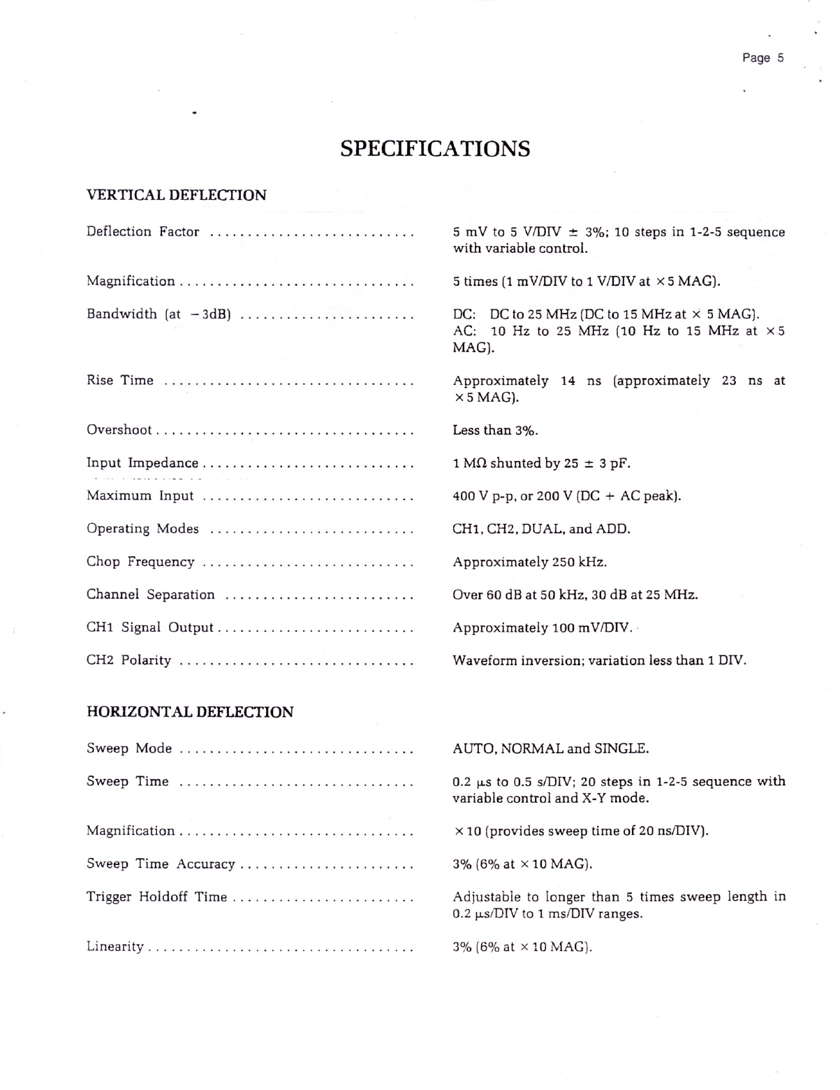
SPECIFICATIONS
VERTICAL
DEFLECTION
Deflection
Factor
..............c.oouviiinnn.
Magnification
c.is
« +
cosmssin
s s
&
smmsawmprs
&
x s
Bandwidth
(at
=3dB)
.iowsidn’s
23
mamienmness5s
s
Rise
Time
.
.......ooiuiiiiiiiiiiiiinnann,
OVErSHOOE
cv.ussemsuiss
s
&
susrarsramsamens
5,5
sistosonsmossgsss
s & &
o
«
Input
Impedance.
.
.
sseuevsin
s
v
s
vvsvmmnss
o ss
Maximu;x;
V
In;ut
............................
Operating
Modes
.
covinnsiiisssssmmnirisine
Chop
Frequency
..............oeeeeuuennnnn.
Channel
Separation
.........................
CH1
Signal
Oulput
,
..o
s
s
s
smmamen
s
s o s
s
CH2:
Polarity’
s«
5 » s
5
5
¢
sogesmmms
b+
45
4
HORIZONTAL
DEFLECTION
Sweep
IMode)
v
s
»
cevitisuis
5
5
=
s
§
5
»
596
SWeeD
TilDE
s
5 v
aemuiens
§ §
&
JEEmes
§ 5 4
59
Magnification
...............
...
ool
Sweep
Time
ACCUTACY
.
..«
.vvvvvnnennennnnn.
Trigger
Holdoff
Timei.
b
«
« »
wemmsrsmons
&
s
«
wa
s
Linearitye
woss
s ¢ 3
snomuens
5 5 §
o
uesme
¥
55
¢ 0
5
mV
to
5
V/DIV
=
3%;
10
steps
in
1-2-5
sequence
with
variable
control.
5
times
(1
mV/DIV
to
1
V/DIV
at
X5
MAG).
DC:
DCto
25
MHz
(DCto
15
MHz
at
X
5
MAG).
AC:
10
Hz
to
25
MHz
(10
Hz
to
15
MHz
at
x5
MAG).
Approximately
14
ns
(approximately
23
ns
at
x5
MAG).
Less
than
3%.
1MQ
shunted
by
25
+
3
pF.
400V
p-p,
or
200
V
(DC
+
AC
peak).
CH1,
CH2,
DUAL,
and
ADD.
Approximately
250
kHz.
Over
60
dB
at
50
kHz,
30
dB
at
25
MHz.
Approximately
100
mV/DIV.
-
Waveform
inversion;
variation
less
than
1
DIV.
AUTO,
NORMAL
and
SINGLE.
0.2
ps
to
0.5
s/DIV;
20
steps
in
1-2-5
sequence
with
variable
control
and
X-Y
mode.
X
10
(provides
sweep
time
of
20
ns/DIV).
3%
(6%
at
x
10
MAG).
Adjustable
to
longer
than
5
times
sweep
length
in
0.2
us/DIV
to
1
ms/DIV
ranges.
3%
(6%
at x
10
MAG).

Page
6
X-Y
Operation
...,
SensttiVILY,
.
wcssssins
«
5
o
sammomes
5
96
&
&
3
semEEE
Frequency
ReSpONSe
«
;s oo
owuvvissss
v
sswmnsvs
TRIGGER
INTENSITY
MODULATION
(Z-axis)
Input
Voltage
...............ccooiiinii.
...
Inputi
Resistants
s
s
s
&
sommamns
6 5
5
§
sussemnsg
Maximum
Input
............................
Frequency
Range
...........................
Mode
selected
with
SEC/DIV
switch:
CH1:
X-axis.
CH2:
Y-axis.
Same
as
CH1
vertical
axis.
DCto
1
MHz
(-3
dB).
CH1,
CH2,
LINE
and
EXT.
INT:
0.5DIV
from
DC
to
15
MHz.
1.5
DIV
from
DC
to
25
MHz.
EXT:
50mV
p-p
from
DC
to
15
MHz.
100
mV
p-p
from
DC
to
25
MHz.
AC,
HF
REJ,
TV,
and
DC.
HF
REJ:
Attenuates
signal
components
.above
50
kHz.
+0r
=,
AUTO,
NORM,
and
SINGLE.
Preset
level
from
50
Hz
to
25
MHz.
Input
Impedance:
1
MQ,
30
pF.
Maximum
Input:
100
V
(DC
+
AC
peak).
3
V
p-p
or
higher
(Bright
at
negative-going
input).
Approximately
5
kQ.
50
V
p-p
(DC
+
AC
peak).
DC
to
5
MHz.
Page
7
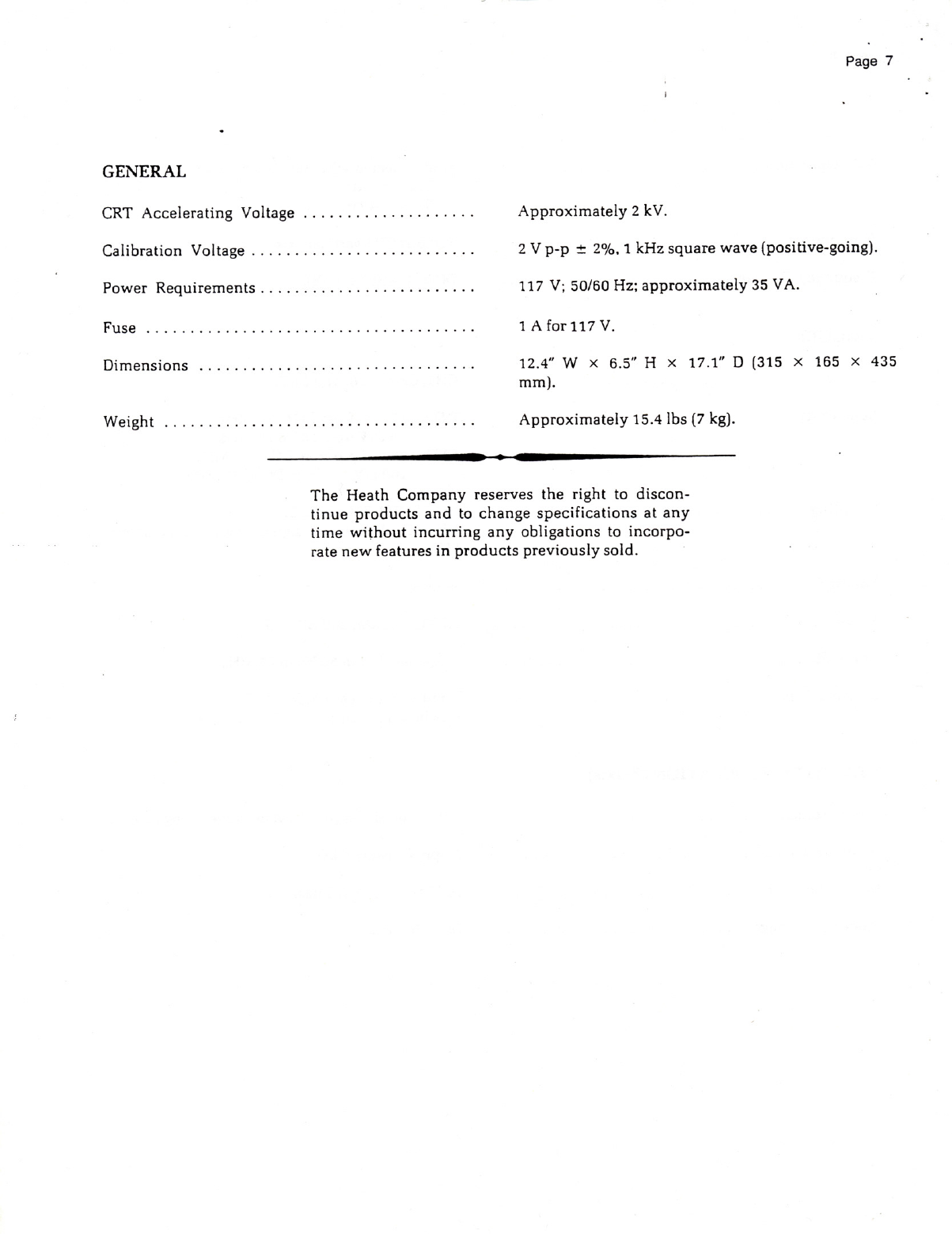
GENERAL
CRT
Accelerating
Voltage
....................
Approximately
2
kV.
Calibration
Voltage
. :
.cuusmiizin
¢
»
o
o
sionaavsiaiia
o
s
«
2V
p-p
*+
2%,
1
kHz
square
wave
(positive-going).
Power
Requirements
..............
...
117
V;
50/60
Hz;
approximately
35
VA.
FUBE
.«
covvmmmnn
»
¢
5
v
vammsen
5
o 5 %
%
s
s
2 5
1Afor117
V.
DIMensions
cwsms
s
s
555
amameis
55
¢
»
¢
e
o
12.4"”
W
X
6.5
H
x
17.1"
D
(315
X
165
X
435
mm).
WEIBHE
.
.
oonoliiths
o
o
o
o
bdeiutiie
8's
3
5
3
samaoni
i
s
5
Approximately
15.4
Ibs
(7
kg).
e
——
<
———
The
Heath
Company
reserves
the
right
to
discon-
tinue
products
and
to
change
specifications
at
any
time
without
incurring
any
obligations
to
incorpo-
rate
new
features
in
products
previously
sold.
Page
8
g
g
25
r@
Heath
25
MHz
osciloscope
{
Posirion
INTENSITY
Pocus
Tace
SeALC
o
50
G
@
POSITION
-
VARIABLE
UL
*
10
ARG
sngt
SWEEP
MODE
(nomw)
W0
woRm
gmet/minT
VERT
moo€
POSITION
CHI
DUAL
cn
q
Pt
voLTs/ov
0O
O
veursrov
&
anioLe
AmiagLE
N
[
10N:
FOR
CONTINUED
{Acamst
1
€
OF
SRR
Raries
(i
PrROTECTION
RE.
REPLACE
ONLY
WITH
THE
SPECIFIED
VOLTAGE
AND
AC
INPUT
l
@3
p
Figure
2
Page
9
OPERATION
CONTROLS
AND
CONNECTORS
Refer
to
Figure
1
and
Figure
2
as
you
read
the
follow-
ing
numbered
paragraphs.
1.
2.
10.
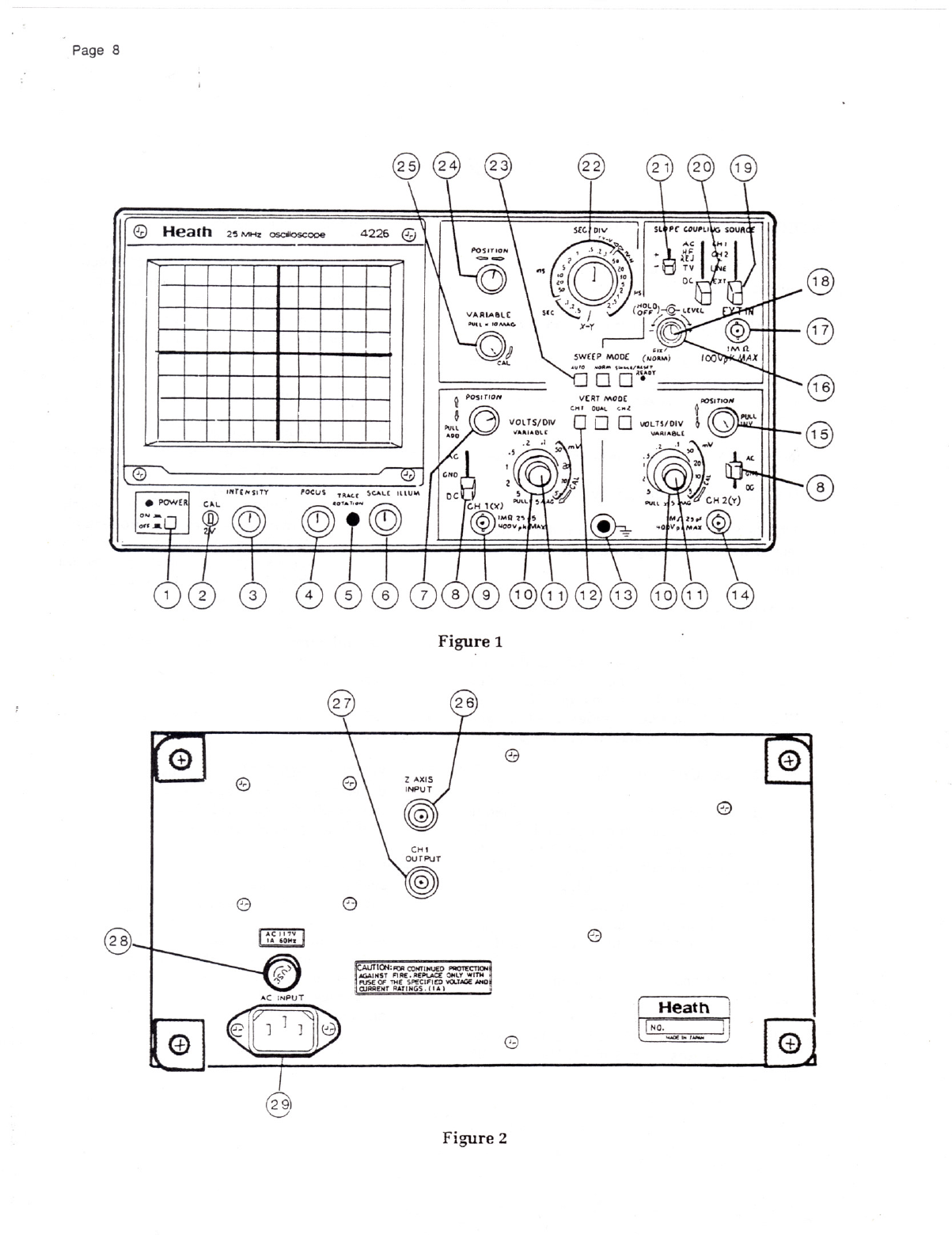
POWER
—
Turns
the
instrument
on
and
off.
CAL
2V
terminal
—
Provides
a
1
kHz
square
wave
output.
It
is
useful
for
checking
amplifier
gain,
waveform
compensation
of
probes,
etc.
INTENSITY
—
Adjusts
the
beam’s
brightness.
FOCUS
—
Adjusts
the
clarity
of
the
beam.
TRACE
ROTATION
—
Used
to
offset
the
ef-
fect
of
the
earth’s
magnetic
field
on
the
trace
line.
SCALE
ILLUM
—
Adjusts
the
scale
back-
ground
light.
POSITION/PULL
ADD
—
Positions
the
CH1
display
vertically.
In
the
X-Y
mode,
using
EXT
IN,
this
control
positions
the
CH1
Y-axis.
When
pulled
out
(ADD
mode),
the
CH1
and
CH2
input
signals
are
algebraically
added.
AC-GND-DC
(CH1
and
CH2)
—
AC:
The
signal
is
capacitively
coupled
to
the
vertical
amplifier
and any
DC
component
is
blocked.
The
low-fre-
quency
limit
(-3dB)
is
about
10
Hz.
GND:
Grounds
the
amplifier
input
and
opens
the
input
circuit.
DC:
All
components
of
the
input
signal
are
coupled
to
the
vertical
amplifier.
CH1
(X)
connector
— BNC
connector
con-
nects
the
input
signal
to
channel
1.
VOLTS/DIV
switch
(CH1
and
CH2)
—
Selects
deflection
factors
from
5
mV/DIV
to
5
V/DIV
in
10
steps.
11.
12
13.
14.
15.
16.
VARIABLE
VOLTS/DIV
control
(CH1
and
CH2)
—
Variable
controls
for
vertical
attenua-
tion.
Provides
continuously
variable
deflec-
tion
factors
(sensitivity)
between
the
steps
of
the
VOLTS/DIV
switch.
Normally
they
are
set
fully
clockwise
(CAL).
When
they
are
pulled
out,
the
sensitivity
is
magnified
by
a
factor
of
5.
VERT
MODE
selector
—
CH1:
Displays
Channel
1
only.
DUAL:
A
dual
trace
display
switches
be-
tween
CH
1
and
CH2,
with
alter-
nate
or
chopped
operation
con-
trolled
by
the
SEC/DIV
switch.
Chopping
occurs
at
approximately
250
kHz
on
the
0.5
s
to
1
ms/DIV
ranges
and
on
alternating
traces
on
the
0.5
ms
to
0.2
ps/DIV
ranges.
CH2:
Displays
Channel
2
only.
Ground
terminal
—
Provides
a
chassis
ground
that
is
connected
to
the
3-wire
AC
power
cord.
CH2
(Y)
connector
—
BNC
connector
con-
nects
the
input
signal
to
channel
2.
POSITION/PULL
INVert
—
Positions
the
CH2
display
vertically.
In
any
X-Y
mode,
this
con-
trol
positions
the
CH2
Y-axis.
When
it
is
pulled
out,
the
CH2
display
is
inverted.
HOLDOFF
—
Adjusts
the
time
between
sweeps,
and
is
used
when
the
time
base
trig-
gering
must
be
delayed
to
display
complex
waveforms
(e.g.
repetitive
complex
pulses).
When
you
turn
this
control
clockwise,
from
full
counterclockwise
(NORM),
the
holdoff
time
is
continuously
variable
from
no
delay
to
5
times
normal
sweep
time.
Operates
only
on
ranges
from
0.2
ws/DIV
to
1
ms/DIV.

Page
10
17,
18
19
20.
21.
22.
EXT
IN
—
A
BNC
connector
for
external
trig-
ger
signals.
In
the
X-Y
mode,
with
the
TRIG-
GER
SOURCE
switch
at
EXT,
the
signal
ap-
plied
to
this
connector
controls
the
X-axis
of
CH1
and/or
CH2.
LEVEL
—
Selects
the
starting
point
voltage
on
the
trigger
source
waveform
at
which
the
sweep
is
triggered.
Turn
the
control
fully
counterclockwise
to
FIX
(NORM)
for
a
fixed
level
(0
volts).
SOURCE
—
Selects
the
triggering
source
sig-
nal
as
follows:
CH1:
CH1
signal
for
triggering.
CH2:
CH2
signal
for
triggering.
LINE:
AC
line-frequency
voltage
for
trig-
gering.
EXT:
The
signal
applied
to
the
EXT
IN
connector
for
triggering.
COUPLING
—
Selects
the
triggering
mode
as
follows:
AC:
Trigger
signals
are
capacitively
coupled
to
the
trigger
circuitry.
Signals
below
10
Hz
are
at-
tenuated.
HF
REJ:
Attenuates
triggering
signals
above
50
kHz.
TV:
For
observing
TV
signals.
DC:
All
trigger
signals
are
directly
coupled
to
the
trigger
circuitry.
SLOPE
—
Selects
the
triggering
point
on
the
positive
or
negative portions
of
the
trigger
sig-
nal.
SEC/DIV
—
Selects
calibrated
sweep
rates
from
0.5
s/DIV
to
0.2
ps/DIV
in
1-2-5
sequence
(20
ranges).
At
X-Y
(fully
counterclockwise),
operation
is
for
the
X-Y
mode.
The
alternate
or
chop
and
TV-V
or
TV-H
operations
are
au-
tomatically
selected
by
the
switch.
23.
24.
25.
26.
27.
28.
29.
SWEEP
MODE
selector
—
AUTO:
For
normal
triggering.
Sweep
free-runs
in
the
absence
of
an
adequate
triggering
signal.
NORMAL:
For
normal
triggering.
No
CRT
display
in
the
absence
of
a
triggering
signal.
Allows
only
one
sweep
until
reset.
Reset
the
cir-
cuit
by
pushing
this
switch.
The
READY
lamp
indicates
when
the
circuit
is
ready
to
be
triggered.
.
SINGLE/RESET:
POSITION
—
Positions
the
CH1
and/or
CH2
trace
horizontally.
VARIABLE/PULL
X10
MAG
—
Provides
con-
tinuously
variable
sweep
rates
to
approxi-
mately
2.5
times
the
calibrated
setting.
At
the
CAL
position,
the
sweep
rate
is
set
by
the
SEC/DIV
switch.
When
you
pull
this
VARI-
ABLE
switch
out,
the
sweep
speed
is
ex-
panded
10
times.
Z
AXIS
INPUT
connector
—
A
BNC
input
connector
for
intensity
modulation
of
the
CRT
trace.
OUTPUT
connector
—
This
BNC
output
con-
nector
provides
the
signal
from
the
CH1
verti-
cal
preamplifier.
Fuseholder
—
Holds
the
AC
line
fuse.
The
rating
is
given
in
the
nearby
table.
AC
INPUT
socket
—
Receptacle
for
the
3-wire
AC
power
cord.

PRELIMINARY
OPERATION
1;
Control
settings:
A.
POWER
switch
to
OFF.
B.
All
three
POSITION
controls
to
mid-
range.
INTENSITY
contrcl
to
midrange.
Push
the
sweep
VARIABLE
knob
(25)
for
normal
conditions.
Push
the
AUTO
button
of
SWEEP
MODE
(23).
VARIABLE
VOLTS/DIV
(11)
pushed
in.
CH1
switch
pushed
in.
Other
controls
may
be
at
any position.
Check
the
AC
line
voltage
and
plug
in-
stallation
on
the
rear
panel.
oo
2
e
2.
Connect
the
AC
line
cord
between
the
AC
INPUT
socket
and
an
AC
outlet.
3.
Set the
POWER
Switch
to
ON.
After
about
20
seconds,
a
trace
line will
appear
on
the
screen.
If it
does
not
appear,
adjust
the
IN-
TENSITY
control
to
increase
brightness
to
suit
your
lighting
conditions.
4.
Adjust
the
FOCUS
and
INTENSITY
controls
for
a
clear
trace
line.
5:
Readjust
the
vertical
and
horizontal
POSI-
TION
controls
to
obtain
the
desired
location.
6.
Connect
a
10:1
probe
to
the
input
of
CH1
and
hook
the
tip
to
the
CAL
2
V
terminal.
2
Set
the
VOLTS/DIV
switch
of
CH1
to
50
mV
and
the
VARIABLE
knob
fully
clockwise.
Set
the
trigger
SOURCE
selector
(19)
to
CH1.
A
square
wave
covering
4
divisions
will
then
be
displayed.
8.
If
the
square
wave
has
excessive
rounding
or
overshoot,
adjust
the
trimmer
in
the
probe.
9.
Remove
the
probe
from
the
CAL
terminal
and
repeat
steps
6
through
8
for
a
second
probe
at
CH2.
The
Oscilloscope
is
now
ready
for
use.
Page
11
TRIGGERING
THE
SWEEP
The
horizontal
(time
base)
circuitry
can
operate
in
three
modes:
AUTO,
NORM,
and
SINGLE.
In
the
AUTO
mode,
triggering
of
the
sweep
occurs
even
in
the
absence
of
an
input
signal.
In
the
NORM
mode,
a
display
occurs
only
when
conditions
estab-
lished
by
the
triggering
controls
and
switches
are
met
(as
described
below).
The
SINGLE
mode
is
iden-
tical
to
the
NORM
mode
except
that
only
one
sweep
can
occur
and
the
RESET
button
must
be
pushed
after
each
sweep
to
enable
the
next
sweep.
The
READY
lamp
indicates
that
the
circuit
is
reset.
Triggered
oscilloscopes
include
circuits
to
display
stable
waveforms.
The
synchronizing
pulse
for
the
triggering
is
derived
from
the
vertical
or
a
time-
related
signal.
It
is
important
that
the
triggering
be
synchronized
with
the
vertical
input.
Five
controls
are
provided
in
this
Oscilloscope
for
this
purpose:
1.
SOURCE
Selector
(19):
CH1:
For
internal
triggering
with
the
CH1
input
signal.
CH2:
For
internal
triggering
with
the
CH2
input
signal.
LINE:
The
AC
line
frequency
is
used
for
triggering.
EXT:
An
external
triggering
signal
con-
nected
to
the
EXT
IN
connector
is
used.
This
provides
three
benefits,
depending
on
operating
condi-
tions:
A.
Triggering
is
not
affected
by
variations
of
the
vertical
sig-
nals.
For
example,
the
trigger-
ing
point
normally
changes
for
changes
in
the
setting
of
the
VOLTS/DIV
switch
since
the
synchronizing
source
voltage
changes.
Unless
the
external
trigger
voltage
is
changed,
triggering
is
very
stable
and
not
dependent
on
the
vertical
control
settings.
B.
You
can
delay
the
input
signal
by
using
the
delay
function
of
a
pulse
generator.
C.
A
composite
or
modulated
signal
can
be
easily
triggered.

Page
12
2.
COUPLING
Selector
(20):
Selects
the
syn-
chronizing
circuit
coupling.
“AC”
is
for
AC
coupling
and
the
DC
component
is
blocked.
At
HF
RE],
a
low-pass
filter
is
used
to
sup-
press
any
RF
noise
interference.
The
TV
set-
ting
is
for
TV
signal
triggering;
selection
is
made
for
TV-V
or
TV-H
by
the
SEC/DIV
switch.
3;
SLOPE
Selector
(21):
Selects
the
trigger
slope,
positive
or
negative,
of
the
trigger signal.
For
TV
synchronizing,
the
point
is
set
to
the
rise
or
fall
time
of
the
pulse.
4.
LEVEL
Control
(18):
For
stable
triggering
con-
trol
over
an
adjustable
range.
The
FIX
(NORM)
position
selects
a
zero
voltage
offset
to
the
trigger
level.
5.
HOLD-OFF
Control
(16):
Improves
triggering
for
_the
.
display..
of
irregular
repetitive
waveforms.
Adjust
as
required
to
delay
retrig-
gering
the
sweep.
X-Y
DISPLAY
OPERATION
For
the
most
common
X-Y
applications,
set
the
SEC/
DIV
switch
to
X-Y,
the
TRIGGER
COUPLING
switch
to
DC,
the
TRIGGER
SOURCE
switch
to
CH1,
and
PUSH
the
CH2
pushbutton
of
the
VERT
MODE
switch.
All
CH1
functions
operate
as
a
horizontal
(X-axis)
amplifier
with
the
horizontal
position
con-
trol,
while
CH2
functions
as
a
vertical
(Y-axis)
amplifier.
For
X-Y
operation
with
dual
Y
channels,
set
the
TRIGGER
SOURCE
switch
to
EXT
and
con-
nect
the
X-axis
signal
to
the
EXT
IN
BNC
connector.
Both
CH1
and
CH2
then
display
Y-axis
signals.
VOLTAGE
MEASUREMENTS
You
can
use
either
the
CH1
or
CH2
input
of
the
Os-
cilloscope
as
a
voltmeter
to
measure
peak,
peak-to-
peak,
DC
voltages,
or
a
specific
portion
of
a
complex
waveform.
1.
Set
the
VARIABLE
control
of
the
VOLTS/DIV
to
the
CAL
position.
Next
set
the
VOLTS/DIV
switch
for
the
trace
amplitude
to
be
used.
Ad-
just
the
vertical
POSITION
control
to
set
the
reference
level.
2:
For
DC
or
compiex
signals,
first
set
the
input
switch
to
GND
and
then
adjust
the
vertical
POSITION
control
for
a
reference
level.
A
positive
voltage
will
deflect
the
trace
upward
and
vice
versa.
For
the
voltage,
multiply
the
vertical
(division)
deflection
by
the
setting
of
the
VOLTS/DIV
switch.
NOTE:
When
a
10:1
probe
is
used,
the
waveform
display
is
only
1/10
of
the
actual
voltage
being
measured.
DUAL
TRACE
DISPLAY
The
MODE
selector
is
set
to
DUAL.
In
this
operating
mode,
procedures
given
above
are
the
same.
SYNCHRONIZING
TV
SIGNALS
Set
the
Trigger
COUPLING
selector
(20)
to
TV.
TV
frame
and
line
triggering
is
automatically
selected
by
the
SEC/DIV
switch.
That
is,
frame
is
selected
on
the
.5
s
to
the
.1
ms
positions, and
line
is
selected
from
the
50 ps
to
the
.2
us
positions.
ADDITION
AND
SUBTRACTION
OPERATION
When
the
CH1
POSITION
knob
is
pulled
(ADD
mode),
the
display
will
be
the
algebraically
added
waveforms
of
CH1
and
CH2.
The
subtracted
waveform
is
displayed
when
the
CH2
vertical
POSI-
TION
knob
is
pulied
for
INVERT.

Page
13
APPLICATIONS
This
Oscilloscope
has
full
capability
for
single
trace
operation
on
each
channel.
For
simplicity,
only
CH1
operation
will
be
referred
to
below.
Control
settings:
AC-GND-DC
switch
............
AC
or
DC
VERT
MODE
selector
...............
CH1
COUPLING
selector
............
AC
or
DC
SOURCE
selector
...................
CH1
Probe
cable
........
Connect
to
CH1
input
Connect
the
probe
tip
to
the
point
of
measurement
and
the
ground
clip
to
the
chassis
or
grounded
area.
NOTE:
The
input
impedance
of
this
instrument
is
1
MQ,
with
25
pF
in
shunt.
With
a
10:1
attenuation
probe,
multiply
the
voltage
reading
by
10.
The
peak-
to-peak
voltage
at
the
point
of
measurement
should
not
exceed
400
V.
AC
VOLTAGE
AND
FREQUENCY
MEASUREMENTS
Initially,
set
the
VARIABLE
knobs
of
the
VOLTS/DIV
and
SEC/DIV
switches
(11)
and
(25)
to
the
CAL
posi-
tions.
An
example
is
shown
in
Figure
3.
From
Figure
3:
P-P
voltage
...........
0.5/div
x
4
=
2V
Peak
voltage
..........
0.5/div
x
2
=
1V
Effective
voltage
........
Peak
V
+
V2
=
0.707V
Frequency,
Hz
........
1/Time
(sec),
where
Time
=
No.
of
DIVs
per
cycle
x
value
of
SEC/DIV
For
the
waveform
in
Figure
3,
frequency
=
=
——
=250kHz.
1 1
1ps
X4
(div)
4ps
e
aav
—
VOLTS/DIV
.
SEC/DIV
.
at0.5Vv
..
atlus
DC
VOLTAGE
MEASUREMENT
Set
the
AC-GND-DC
switch
to
GND.
Push
the
SWEEP
MODE
switch
(23)
to
AUTO
and
then
posi-
tion
the
trace
on
one
of
the
scale
lines
for
a
0
V
reference.
Set
the
AC-GND-DC
switch
to
DC.
The
trace
will
shift
upward
for
+
or
downward
for —
polarity.
DC
voltage
=
Shift
in
divisions
x
VOLTS/DIV
setting.

Page
14
AM
MODULATION
MEASUREMENT
There
are
several
methods
of
measuring
AM
mod-
ulation,
but
here
the
envelope
method
is
shown.
This
method
is
applicable
only
if
the
carrier
fre-
quency
is
within
the
bandwidth
of
this
instrument.
Figure
4
shows
the
display
of
a
modulated
wave.
DUAL
TRACE
APPLICATIONS
For
this
application,
set
the
VERT
MODE
selector
to
DUAL.
Signals
at
Channel
1
and
2
will
be
dis-
played
simultaneously.
The
two
signals
can
then
be
compared
with
respect
to
level,
waveform,
phase,
etc.
SOURCE
OUTPUT
COMPARISON
OF
LEVELS
An
example
of
interconnections
is
shown
in
Figure
5
for
the
output/input
level
comparison
of
an
amplifier.
Set the
displays
of
CH1
and
CH2
to
be
superimposed
using
the
POSITION
controls.
The
gain
in
the
amplifier
will
be
the
difference
in
settings
of
the
re-
spective
VOLTS/DIV
switches.
When
the
signals
cannot
be
matched,
even
if
the
VARIABLE
controls
are
adjusted,
the
difference
is
due
to
distortion
in
the
amplifier.
In
this
case,
set
the
VERT
MODE
selec-
tor
to
ADD
and
pull
the
POSITION
knob
of
CH2
to
view
only
the
distortion;
the
trace
will
be
a
straight
line
when
distortion
is
absent.
CHECKING
STEREO
SYSTEMS
Stereo
"audio
systems
have
two
~
symmetrical
amplifier
circuits.
Using
the
dual
trace
feature,
it
is
possible
to
compare
and
check
the
operation
in
each
circuit.
Location
of
any
defective
portion
is
thus sim-
plified.
SERVICING
TV
SETS
In
this
application,
a
triggered
oscilloscope
is
indis-
pensable.
This
instrument
can
synchronize
to
either
the
TV-V
(Frame)
or
TV-H
(Line)
of
the
video
signal
to
display
the
blanking
pedestal,
VITS,
or
vertical/
horizontal
synchronizing
pulses.
OSCILLOSCOPE
CH1
INPUT
o
AMP
[
R
LOAD
Y
%
o
I—g
CH2
[
Figure
5

COMPOSITE
VIDEO
ANALYSIS
The
most
important
waveforms
in
TV
servicing
are
the
composite
signals
consisting
of
the
video,
blank-
ing
pedestal
and
sync
pulses.
Figures
6
and
7
show
composite
signals
synchronized
with
horizontal
synchronizing
and
vertical
blanking
pulses.
BURST
VIDEO
"
HORIZONTAL
HORIZONTAL
SYNC
PULSE
BLANKING
PULSE
Figure
6
VIDEO
VERTICAL
VERTICAL
SYNC
PULSE
BLANKING
Figure
7
Page
15
FREQUENCY
MEASUREMENT
WITH
X-Y
METHOD
Set
the
SEC/DIV
switch
and
trigger
switches
for
X-Y
operation.
Connect
a
standard
frequency
signal
to
CH1
and
the
unknown
signal
to
CH2.
Then
CH1
is
the
X-axis
and
CH2
the
Y-axis.
The
display
will
be
the
lissajous
figure,
examples
of
which
are
shown
in
Figure
8.
(AR
e
@
rassss
swomn
JOORN
Figure
8
;|
(6
PHASES
SHOWN)
PHASE
MEASUREMENT
Using
the
X-Y
function,
connect
the
two
input
sig-
nals
to
the
CH1
and
CH2
connectors.
The
phase
is
calculated
with
the
relation
shown
in
Figure
9.
SINE
0
n
8
A
PHASE
ANGLE
©
n
Figure
9
CHI
CHI
(x)
ATT
CH2
()
@
ATT
EXT
IN@———
GENERATOR
CAL
O=—
CALIBRATOR
CHI
ouTPUT
__________
a
VERTICAL
DEFLECTION
UNIT
|
|
|
CRT
6*
CH1
|
-
7
PRE
AMP
—
VERTICAL
|
{—=
CHI
|
lswreHng]
OUTPUT
AMP
|
-
TRIG
AMP
T
|
(
MODE)
|
SELECT
|
CH2
|
™
PRE
AMP
(
TRIG
|
CH2
SELECT
I
TRIG
AMP
[
|
t
| |
s
esatemsss
s
s
e
e
i
iy
HORIZONTAL
DEFLECTION
UNIT
E
2Ky
INT
TRIG.
(X
AXIS)
|
I
-
- %
|
E
s
TETT
-1
.
:
1 ) |
)
1|
crT
HV
:
TRIGGER
SWEEP
HORIZONTAL
|
HORIZONTAL[———
1
{conTROL[™]
supeLy
)
GENERATOR
SWITCHING
QUTPUT
AMP)
|
¥
]
I
:
[z
axis
|
:
AMP
i
el
i
bt
e
BRI
o
S
e
s
s
J
| i
" I
i
PoweR
F—
.
_CRT
CIRCUIT
.
SupPLY
—
Z
AXIS
INPUT
Figure
10
Block
Diagram

Page
17
CIRCUIT
DESCRIPTION
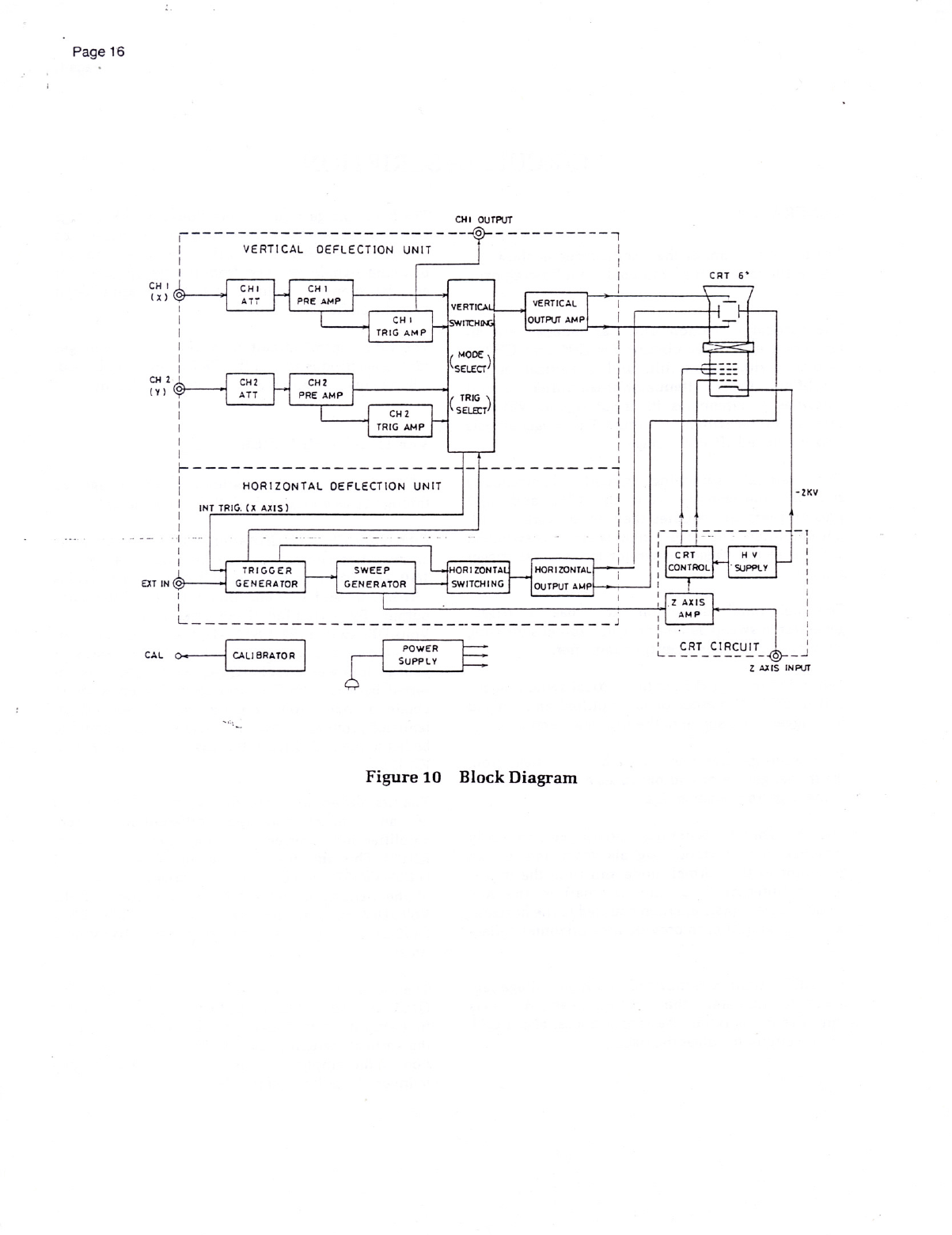
GENERAL
The
block
diagram
of
the
Oscilloscope
is
shown
in
Figure
10.
Refer
to
it
as
you
read
the
following
para-
graphs.
The
vertical
deflection
unit has
independent
at-
tenuator/preamplifier
circuits
for
CH1
and
CH2,
a
vertical
switching
circuit,
and
a
vertical
output
amplifier.
Each
attenuator/preamplifier
circuit
amplifies
or
attenuates
its
input
signal,
which
is
then
fed
to
the
switching
circuit.
The
trigger
signals
also
are
picked
off
at
this
stage.
The
vertical
switching
circuit
electronically
switches
the
signals
from
the
CH1
and
CH2
preamplifiers
and
couples
them
to
the
vertical
out-
put
amplifier.
The
trigger
signals
are
also
switched
and
fed
to
the
trigger
generator
for
internal
trigger
signals.
The
horizontal
deflection
unit has
a
trigger
generator,
a
sweep
generator,
a
horizontal
switching
circuit
and
a
horizontal
output
amplifier.
The
switching
signal
from
the
vertical
switching
cir-
cuit
or
EXT
IN
connector
is
amplified
and
shaped
to
a
trigger
pulse
signal
in
the
trigger
generator.
The
sweep
generator
is
driven
by
the
pulses
from
the
trigger
generator
and
produces
a
sawtooth
signal
in
the
triggered
sweep
mode.
The
horizontal
switching
circuit
electronically
switches
the
sawtooth
signals
from
the
sweep
generator
in
the
normal
mode
and
from
the
trigger
signals
(internal,
line,
and
external)
in
the
X-Y
mode.
These
signals
are
then
coupled
to
the
horizon-
tal
output
amplifier
to
provide
the
horizontal
deflec-
tion.
The
CRT
circuit
is
comprised
of
a
high
voltage
reg-
ulator
to
accelerate
the
electron
beam,
a
Z-axis
amplifier
to
blank
out
the
return
traces,
and
a
CRT
control
circuit
to
adjust
the
trace.
The
high
voltage
regulator
provides
a
2.0
kV
voltage
to
be
applied
to
the
CRT
cathode
to
accelerate
the
electrons.
The
Z-axis
amplifier
amplifies
the
un-
blanking
signals
received
from
the
sweep
generator
and
the
intensity
modulating
signal
for
application
to
grid
1
of
the
CRT.
The
CRT
control
circuit
provides
various
voltages
for
the
electrodes
so
that
the
CRT
is
properly
biased.
All
the
power
supplies
are
regulated
for
stability.
VERTICAL
AMPLIFIER
NOTE:
Refer
to
the
schematic
diagrams
on
Pages
25
through
30
as
you
read
the
following
paragraphs.
Each
of
the
CH1
and
CH2
attenuator
circuits
consists
of
two
attenuators.
The
first
attenuator
is
for
1/1,
1/10,
and
1/100,
and
the
second
attenuator
provides
1/1, 1/2,
1/4
and
1/10
portions
of
the
first
attenuator
output.
By
switching
these
attenuators
with
the
Volts/DIV
switch
(S2-1/S102-1),
the
signal
can
be
at-
tenuated
in
a
range
of
1/1
to
1/1000
in
10
steps.
A
voltage
follower
circuit
(Q1-Q4/Q101-Q104)
is
in-
serted
between
the
first
and
second
attenuators
to
obtain
a
high
input
impedance.
The
second
at-
tenuator
provides
a
low-impedance
output
signal
to
be
fed
to
the
first
differential
cascade
amplifier
(IC2/
1C102).
The
first
differential
cascade
amplifier
is
comprised
of
an
emitter-connected
differential
current
amplifier
and
a
current-to-voltage
converter
(IC2
or
1C102).
This
amplifier
also
has
the
Variable
circuit
(VR39/VR139)
for
continuously-variable
adjustment
of
the
deflection
factor
between
the
steps
of
the
Volts/DIV
switch,
and
the
X5MAG
switch
(S2-2/
$102-2)
for
magnifying
the
vertical
sensitivity
by
5
times.
The
second
differential
cascade
amplifier
(Q5,6.7,8/
Q105,
106,
107
—
110)
amplifies
the
output
from
the
first
amplifiers
to
a
level
that
is
sufficient
to
drive
the
vertical
switching
circuit.
The Q109.
Q110
por-
tion
of
the
amplifier
is
used
with
the
INV
switch
to
invert
the
polarity
of
the
CH2
signal.

Page
18
The
output
signal
of
the
second
amplifier
is
fed
di-
rectly
in
the
form
of
a
current
signal
to
the
diode
gate
network
of
the
vertical
switching
circuit.
The
current
signal
for
vertical
positioning
of
the
trace
is
added
to
the
current
signal
in
the
second
amplifier,
and
is
controlled
by
VR54/VR154
in
the
positioning
circuit.
A
signal
within
each
of
the
second
amplifiers
is
amplified
by
Q10
or
Q111,
and
fed
to
the
vertical
switching
circuit
as
an
internal
trigger
signal.
At
CH1,
a
signal
is
also
fed
to
the
CH1
Output
terminal
through
impedance
converter
Q11.
The
vertical
switching
circuit
determines
whether
the
CH1
or
the
CH2
preamplifier
signal,
or
both,
will
be
connected
to
the
vertical
output
amplifier
circuit.
This
circuit
is
comprised
of
diode
gate
circuits,
which
electronically
switch
the
vertical
signals
of
CH1
and
CH2,
and
a
switching
buffer
(Q201,
202)
which
provides
the
switched
signals
to
the
vertical
output
amplifier.
The
switching
buffer
output
is
routed
through
a
delay
line
(DL1)
which
allows
the
sweep
waveform
to
start
before
the
vertical
signal
is
applied
to
the
CRT.
Drive
amplifier
Q301/Q302
in
the
vertical
output
amplifier
is
a
feedback
amplifier,
with
a
low
output
impedance
for
driving
the
final
amplifier.
The
final
amplifier
circuit
provides
the
final
amplification
for
the
signal
and
applies
it
to
the
vertical
deflection
plates
of
the
CRT.
Transistors
Q303-Q306
supply
the
necessary
current
for
driving
the
final
stage
tran-
sistors,
Q307—Q310.
The
signal
is
voltage-amplified
in
this
stage
and
fed
to
the
CRT
for
vertical
deflec-
tion.
HORIZONTAL/TIME
BASE
The
trigger
generator
is
comprised
of
a
pulse
generator
circuit
which
produces
a
trigger
pulse
sig-
nal
for
driving
the
sweep
generator,
and
an
AUTO
circuit
which
produces
a
free-running
signal
for
au-
tomatic
sweep
operation
when
no
trigger
is
applied.
The
trigger
pulse
generator
circuit
includes
a
source
switch
(S401),
a
coupling
switch
(5402),
an
imped-
ance
converter
(Q403),
a
level
comparator
(Q404,
Q405),
a
TV
synchronization
separator
(Q410,
Q411),
and
a
Schmitt
trigger
circuit
(IC401).
The
source
switch
selects
the
internal
trigger
signal
fed
from
Q401,
the
line
trigger
signal
from
R1025,
or
an
external
signal
from
P405.
The
selected
signal
is
fed
to
the
coupling
switch.
The
coupling
switch
selects
the
mode
of
trigger
cou-
pling.
In
the
AC,
HF
REJ
and
TV
modes,
the
DC
component
of
the
trigger
signal
is
blocked
by
cou-
pling
capacitor
C409
and
the
frequency
components
below
10
Hz
are
attenuated.
In
the
HF
RE]
trigger
coupling
mode,
the
high
frequency
components
of
the
trigger
signal
above
about
50
kHz
are
attenuated,
while
the
lower
frequency
components
(between
about
10
Hz
and
50
kHz)
are
passed
without
attenua-
tion.
In
the
TV
mode,
the
sync
signal
is
separated
from
the
video
signal
by
the
TV
synchronization
separator.
The
DC
mode
of
trigger
coupling
passes
all
signals
from
DC
to
25
MHz
and
above.
Impedance
converter
Q403
is
an
FET
source
fol-
lower.
It
provides
a
high
input
impedance
for
the
trigger
signal
and
operates
as
a
buffer
between
the
trigger
generator
circuit
and
the
trigger
signal
sources.
The
output
signal
from
the
impedance
con-
verter
is
fed
to
the
level
comparator
circuit.
i
The
level
comparator
(Q404,
Q405)
is a
differential
amplifier
which
selects
the
rising
edge
(or
the
falling
edge)
of
the
impedance
converter
output
signal.
The
comparator
highly
amplifies
any
voltage
difference
between
the
impedance
converter
output
and
the
re-
ference
level
from
the
Level
control
VR441/S441.
At
the
Fix
position
of
the
Level
control,
the
trigger
point
is
locked
at
the
center
portion
of
the
trigger
range
by
feeding
the
output
of
the
level
fixing
circuit
(Q406—Q409)
back
to
Q405.
The
slope
of
the
trigger
signal
is
selected
by
Slope
switch
S403.

The
output
signal
of
the
level
comparator
is
fed
to
the
buffer
amplifier
(Q410-413)
and
amplified
suffi-
ciently
to
drive
Schmitt
trigger
circuit
IC401.
The
output
of
IC401
drives
the
sweep
generator
and
the
auto
circuit
(Q601,
Q602)
which
converts
the
high
speed
pulse
signal
of
the
Schmitt
trigger
circuit
into
a
DC
signal
for
operating
the
sweep
generator
in
the
Auto
mode.
The
sweep
generator
includes
a
sweep
gate
circuit
(IC601-1/2),
a
sweep
start
comparator
(Q603, Q604),
a
sweep
enable
circuit
(IC601-1/2)
a
hold
off
circuit
(Q613),
a
sawtooth
sweep
generator
and
a
sweep
length
circuit
(Q616).
The
sawtooth
sweep
generator
is
comprised
of
a
gate
transistor
amplifier,
a
Miller
integrator,
an
integration
time
constant
switching
circuit
and
a
SEC/DIV
switch
which
controls
the
switching
circuit.
The
sweep
generator
produces
the
sawtooth
voltage
that
is
amplified
by
the
horizontal
amplifier
to
pro-
vide
horizontal
deflection
on
the
CRT.
This
circuit
also
produces
the
gate
waveform
used
by
the
Z-axis
circuit
to
unblank
the
CRT
during
the
sweep
time.
Gate
transistor
amplifier
Q603
alternately
resets
the
two
selectable
sweep
ramp
capacitors
(C606/607
or
C606/607/608)
through
Q605
and
Q606
or
allows
the
capacitors
to
charge.
A
constant
current
from
Q608
generates
a
bias
(zero)
current
through
R618,
Q612,
D621,
D622,
and
R621.
A
current
selected
by
the
SEC/DIV
switch
is
generated
by
the
IC603/Q611
cir-
cuit
and
charges
the
sweep
capacitors
also
through
the
same
bias
circuit.
The
current
difference
produc-
esaramp
at
R621.
The
sawtooth
voltage
ramp
is
fed
to
the
horizontal
output
amplifier
through
switching
circuit
1C602,
which
selects
the
internal
or
external
signals.
The
horizontal
output
amplifier
consists
of
a
drive
amplifier
and
an
output
amplifier.
The
drive
amplifier
(Q801-Q804)
converts
the
single-ended
signal
from
the
switching
circuit
into
a
push-pull
signal
for
driving
the
output
amplifier.
The
gain
of
this
amplifier
can
be
multiplied
by
a
factor
of
10
for
the
x
10
MAG
operation.
Page
19
The
output
amplifier
(Q805-Q812)
which
consists
of
two
single-ended
feedback
amplifiers,
amplifies
the
signal
at
its
input
to
produce
the
output
to
drive
the
horizontal
deflection
plates
of
the
CRT.
The
sig-
nal
current
amplified
by
Q805
and
Q806
is
con-
verted
into
a
voltage
signal
by
Q807-Q812
to
obtain
a
sufficiently
high
level
and
a
low
output
imped-
ance.
By
means
of
negative
feedback
resistors
(R817,
R818),
stable
gain
and
a
wide
flat
frequency
response
are
achieved.
CALIBRATOR
The
calibrator
circuit
provides
a
square-wave
output
signal
with
an
accurate
voltage
of
2
V
p-p
(=
2%)
which
is
used
to
calibrate
the
vertical
deflection
fac-
tor.
The
calibration
signal
is
produced
by
generating
a
signal
with
the
multivibrator
(1C4001-1/4,
2/4),
shaping
the
waveform
with
the
Schmitt
circuit
(IC4001-3/4,4/4),
and
dividing
the
voltage
signal
with
resistors
R4009-4012.
CRT
CONTROL
The
CRT
control
circuit
provides
the
voltage
levels
and
control
circuits
necessary
for
operation
of
the
CRT.
Q2001
and
its
associated
circuitry
compose
the
high-frequency
oscillator
which
produces
the
drive
for
high
voltage
transformer
T2001.
The
high
voltage
output
is
rectified
by
D2010
and
D2011,
and
con-
verted
into
—2000
volts
DC.
This
high
voltage
is
supplied
to
the
CRT
cathode
as
an
acceleration
volt-
age,
and
is
stabilized
by
the
regulator
circuit
(1C2001).
POWER
SUPPLY
The
low
voltage
power
supply
circuit
supplies
the
operating
power
for
the
Oscilloscope
from
four
regu-
lated
power
supplies
(+160
V,
+5
V,
+12V,
—12
V)
and
one
unregulated
power
supply
(+16
V).
The
output
voltages
of
the
two
windings
of
the
power
transformer
are
rectified
and
then
regulated.

Page
20
MAINTENANCE
&
ADJUSTMENTS
GENERAL
MAINTENANCE
Preventive
Maintenance
—
Clean
and
recalibrate
the
Oscilloscope
on
a
regular
basis
to
keep
the
instru-
ment
looking
nice
and
working
well.
Cleaning
—
Remove
any
dirt,
dust
and
grime
whenever
they
become
noticeable.
You
can
remove
dirt
from
the
outside
covers
with
a
soft
cloth
moist-
ened
with
a
diluted
household
cleaning
solution.
Recalibration
—
Recalibrate
the
Oscilloscope
at
reg-
ular
intervals;
after
1000
hours
of
operation,
for
ex-
ample,
or
twice
a
year
if
used
daily.
Servicing
—
Should
the
Oscilloscope
ever
become
inoperative
or
damaged,
refer
servicing
to
a
qualified
repair
facility.
ADJUSTMENT
AND
CALIBRATION
WARNING:
Be
careful
when
you
are
calibrating
the
Oscilloscope;
dangerous
high
voltage
is
present
in
several
areas.
12V
=12y
+5V
+160V
VERT. PCB
VR1006
a9
+12v
ADT
Rear
side
NOTE:
Some
controls
are
factory
preset
and
are
not
included
in
this
calibration
procedure.
These
need
no
adjustment
unless
you
replace
those
parts.
In
this
event,
contact
the
Heath
Customer
Service
depart-
ment.
Power
Supply
Adjustments
(Figure
11)
1.
+12V
adjustment
—
Adjust
VR1006
for
+12
+
0.05
V
between
pin
2
on
connector
P1007
and
ground.
Adjust
this
voltage
very
care-
fully,
as
it
provides
a
reference
for
other
supplies.
2;
—12V
check
—
Check
pin
3
on
P1007
for
proper
voltage,
—12
=
0.2V.
3.
+5Vcheck
—
Chec'kvbinr‘}
on
P1007
for
pfoi)-
er
voltage,
+5V
=
0.25V.
4.
+160V
check
—
Check
pin
6
on
P1007
for
proper
voltage,
+160V
=
5V.
—2000V
check
—
Check
pin
3
on
connector
P2005
for
—2000V
=
50V.
Use
a
high
input
impedance
voltmeter
(10
MQ
or
more)
rated
for
high
voltage
measurements.
w
HORIZ.
PCB
Rear
side
Figure
11
Check
points
of
DC
supply.
Table of contents


