Heathkit SB-401 User manual

595-947-01
10-17-69
MODEL 58 ..401
sse
TRANSMITTER
®
•
PRIce $2.00
-
Copy'
Ight'~
1966
Hedth Company
.ASSE1VLBLY
•


HEATH COMPANY
Use extreme care during initial testing
and all subsequent operation of this
Transmitter. While the 5B-401 is de-
signed for maximum safety, never lose
respect for the high voltage present in
thi
s unit. AIways protect yoursel"f a-
gainst lethal or severe electric shock.
CAUTION
•
OCR, applied now searchable.

147
148
139
141
132
132
134
134
134
136
137
129
130
130
131
131
132
12 5
125
126
126
126
128
117
118
120
121
105
108
108
109
109
109
110
III
112
1 13
11 5
103
97
97
97
98
99
99
99
100
101
101
102
102
'.
.. .. .. .. .. .. .. .. .. .. .. .. .. .. .. ..
.. .. .. .. .. .. .. .. .. .. .. .. .. .. .. ..
SCHEMATIC ..... (fold-out from P age)
REPLACEl\1ENT PARTS PRICE LIST
• •
•
.. .. .. .. ..
"
.
..
.
"
.. ..
"
.. ..
•
• •
..
.
.. .. .. .. .. .. .. .. .. ..
"
..
.
CIRCUIT BOARD X-RAY VIEWS
CIIASSIS PHOTOGRAPHS .. .
Heterodyne Oscillator And H eterodyne-Oscillator
Amplifi er .................... ............................"
Heterodyne Mix er .
Driv er ..
Final Amplifiers .
Automatic Level Control .
Power Supp ,ly .
l\letering Circuits . . . . . . . . . . . . . . . . . . . . . . . .
"
.. ..
.
..
.
..
.
.
.. .. .. .. .. ..
.. .. ..
.
•••
Isolation Amplifier . . . . . . .
Symmetrical Crystal Bandpa ss Filt er . . . . . . . . . . .
Linear Master Oscillator . . . . . . . . . . . . . . .
LMO Mixer . . . . . . . . . . . . . . . . . .
.. .. .. .. .. .. .... .. .. .. .. ..
Balanced Modulator . . . . . . . . . .
"
"
.. ..
.. .. .. .. .. .. .. .. ..
"
..
.
..
..
.
.
.. .. ..
Cathode Follower .
.. .. .. .. ..
.. .. ..
"
.. .. ..
.
..
.. .. .. ..
.. .. .. ..
Schematic Diagram . . . . . . . . . . . . . . . . . . .
Frequency Chart .
Audio Preamplifier And Cathod e Follow er _ . . . . .
VOX Amplifier . . . . . . . . . . . . . . . . . . . .
Relay And Anit-VOX Amplifi er .
Tone Oscillator And Tone Amplifi er . . . . . . . . . .
LSB-USB-CW Carrier Generator And
CIRCUIT DESCRIPTION
. .
.. .. .. .. ..
.
.. ..
.
.. .. ..
.
.. .. ..
.
.. ..
.
.. .. ..
SPECIFICATIONS
..
.
.
.
..
.
..
.. .. .. ..
.
.. .. .. .. .. ..
.
.. ..
. .
.
.. ..
.
..
.
.
.. .. .. ..
.
.. .. .. .. .. .. .. .. .. .. .. ..
Troubleshooting Chart
Factory Repair Service
.
.. .. ..
.
.
.
..
.
.
.
.. .. .. .. .. .. .. .. .. ..
IN CASE OF DIFFICULTY
•
•
•
Transmitter Operation Onl y . . . . . . . . . . . . . . . .
CW Tune-U p .. . . . . . . . . . . . . . . .. .
SSB Tune -U p . . . . . . . . . . . . . . . . . . . . . . . . . .
..
. .
.. .. .. .. .. .. ..
.. ..
"
"
.
SSB .
..
.
.. .. .. .. .. .. .. .. ..
• •
..
.
.
..
"
.. ..
.
.
..
. .
..
"
..
.
.. ..
Meter .Readings . . . . . . . . . . . . . . . . . . . . . . . . .
Reading Transmitter Frequ ency .
Operating
Conditions .
Transmitt er Operation . . . . . . . . . . . . .
Operation With S8 -303 Re ceiver . . . . . . . . . . . . . .
~W ......................""....
•
•
•
"
..
.
.
.
.. .. .. .. ..
. .
INSTALLATION AND OPERATION ..
.. .. .. .. .. .. .. .. .. .. .. .. .. .. .. .. .. ..
FINAL ASSEMBL
Y . . • . . . .
.. .. .. .. .. .. .. .. ..
"
.. .. .. .. .. .. .. .. ..
.. ..
"
..
• •
•
Microphone Conn ection . . . . . . . . . . . . . . . . . .
LMO Adjustment . . . . . . . . . . . . . . . . . . . .
Frequency Shift Adju stment . . . . . . . . . .
Final Tran smitter
Adjustment .. . . . . . .
Driver ...............".."......"...."............"",,....
8.6
Megahertz Trap Adjustm ent .
Carri er Null Adjustment . . . . . . . . . . . . . . . . . . . . .
N
eu
tralizing ...."........ .."........ ".............
II .. II " ..
Final
Bias .............." ..........""........................
•
• •
.. .. .. ..
"
.. .. ..
.. ..
" "
.. .. .. ..
..
.
.. .. .. ..
.
"
.. .. ..
.. .. ..
.
•
•
•
.
..
"
..
"
..
.
"
"
"
.. .. ..
"
"
..
21 Megahertz Trap ....
Heterodyne Oscillator . . . . . . .
Carrier Generator . . . . .
CONTENTS
96
97
97
90
90
90
90
91
92
93
94
94
95
95
96
87
75
78
79
81
82
85
73
35
39
54
55
63
64
33
16
21
24
13
8
10
5
6
4
3
Page 2
.. .. .. .. .. ..
•
•
•
•
.. .. .. .. ..
Microphone COllnection . . . . . . . . . . . . . . . . . . . . .
LMO Adjllstment . . . . . . . . . . . . . . . . . . . . . . . .
Final Transmitter Adjustment . . . . . . . . . . . . .
Alignm ent With SBA401-1 Crystal Ac cesso ry Kit In stalled
Crystal In" stallation .
Equipm ent Required • . . . . . . . . . . . . . . .
8.6
Megahertz Trap . . . . . . . . . . . . . . . . .
.. .. .. ..
.
.. .. .. .. .. .. .. .. ..
.. .. .. ..
.. .. .. .. .. .. .. ..
•
•
•
.. .. .. .. .. .. .. .. .. .. .. .. .. .. .. ..
.. .. .. .. .. .. .... ..
.
..
.
.. ..
.
Driv er .
8.6
Megahertz Trap Adju stment
Carri er Null Adju stment . . . .
Neutralizing .
Final Bia s
II .. .. .. .. .. .. .. .. .. ..
.. .. .. ..
.. .. .. ..
.. ..
,.
..
•
•
•
Alignm e nt
With
S B - 303
Reteiver As A
r rrans ce iv e r . . . . . . . . . . .
8.6
Megahertz Trap . . . . . . . . . . .
21 M egahertz Trap .
Carri er Gen erator . . . . . . . . . . . . . . . . . .
ALI GNM EN1'
.. .. .. .. .. .. .. .. .. .. .. .. .. .. .. .. .. .. .. .. .. .. .. .. .. .. ..
INITIAL TEST
Parts List
#
5 .
Step-B y-Step A ssembly
Dial A ssembly .
Parts Mounting-Front Pan el .. . . . . . . . . . . . . . . . . .
Wiring Front Panel To Cha ssis . . . . . . . . . . . . . . . . . .
Front Pan el Mounting . . . . . . . . . . . . . . . . . . . . . .
Final Wiring-Chassis Top .
Final Wiring-Chassis Bottom . . . . . . . . . . . . . . . . . . .
FINAL WIRING
.. .. .. ..
•
•
•
.. .. .. .. ..
.. .. .. ..
•
•
•
•
•
•
•
•
•
.. .. .. .. .. .. .. ..
•• •
.. .. .. ..
•
•
•
.. .. .. .. .. ..
Parts List
#4 .
Step-B y-Step Assembly
Preliminar y Wiring-Chassi s Top .
Preliminar y Wiring-Chassis Bottom . . . . . . . . . . . . . . . .
Parts Mounting On Carrier Generator Shield
Wiri ng Carrier Generator Shield To Cha ssis .... . . . . .
Tran sformer Wiring . . . . . . . . . . . . .
Preliminary Wiring-Band Switch .....
CHA SSIS WIRI NG
•
••
•
•
•
.. .. .. .. ..
•
• •
.. .. .. .. ..
• • •
Parts
List
#
3 ..
Step-By-St ep Assembly
Parts Mounting-Chassis Bottom .
Coil Mounting-Chassis Top .
Parts Mounting-Chassis Top .
CHASSIS PARTS MOuNTING
.. .. .. ..
J .. .. .. .. .. ..
..
.. .. .. .. .. ..
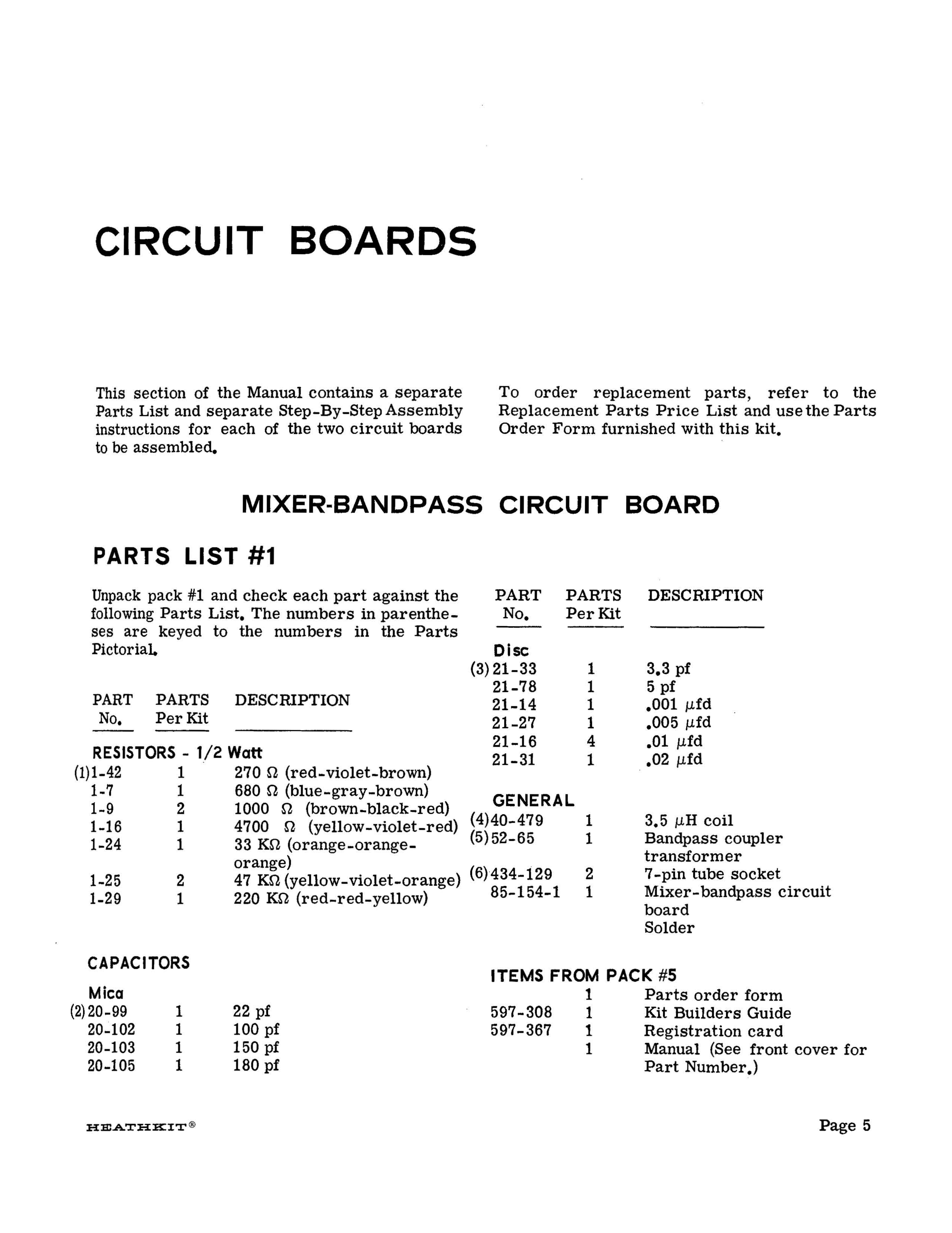
Mixer-Bandp ass Circuit Board
Parts List
#
1 . . . . . . . . . .. . . .. . . .. . . . . . . .
Step-By -Step A ssembly .
Carri er G enerator Cir cuit Board
Parts
List
#
2 . . . . . . . . . . . . . . . . . . .
Step-By -St ep A ssembly .
CIR CUIT BO ARDS
• .. • • •• • •• .. • • II .. • • .. .. ..
UNPACKING INSTRUCTIONS
..
.
.. ..
. .
.. .. .. ..
.
..
.
..
.
..
•
•
•
INTRODUCTION .... . . .
OF
TABLE

Page 3
Refer to the
"Kit
Builders Guide" for complete
information onparts identification, tools, wiring,
soldering, and step-by-step assembly proced-
ures.
Other operating features include: voice oper-
ated
(VOX)
and push-to-talk
(PTT)
control in
the 8SB mode; break-in keying in
the
CW
mode; built-in antenna change-over relay;
SWitched 120
V
AC to operate an external an-
tenna
relay; crystal filter type SSB generator;
and automatic level control to prevent distor-
tion while providing high talk power. The large
circular dial has calibration marks every kilo-
hertz and covers 100 kilohertz for every revo-
lution to provide a
bandspread
equal to approxi-
mately 10 feet per megahertz. Aslide-rule-
type dial pointer clearly indicates the number of
rotations of the circular dial. The knob-to-dial
ratio is approximately
4:1.
All-aluminum metal parts provide light-weight
and sturdy construction. Assembly time-saving
features include circuit boards, wiring cable
assemblies, and
a
preas sembled LMO tuning
unit,
The transformer-operated, silicon diode
power supply' is
a
long-life, low-heat power
source.
Complete Transceive capabilities are available when the
Transmitter is used with the Heathkit Model SB-300, SB-301,
or 5B·303 Receiver. The Transmitter can also be used with
other receivers
by
installing the SBA-401-1 Crystal Accessory
Kit
in the Transmitter. This Transmitter is compatible with
the
Heathkit Model SB-200 SSB Linear Amplifier.
The Heathkit Model SB-401 SSB Transmitter
is capable of SSB (upper or lower sideband) and
CW
operation on all amateur bands from
3.5
to
30
megahertz. A crystal-controlled heterodyne
oscillator and a preas sembled, pre aligned linear
master oscillator insure highly accurate and
stable operation.
DUCTI
INTR

:B:E.A.THKI:T@
Page 4
PICTORIAL
PARTS
NOTE: To avoid intermixing parts, do not open
any of the parts packs until directed to do so
at the beginning of one of the Parts Lists.
Any
part that is packed in an individual envelope
with a part number on it should be placed back
in its envelope, after it is identified, until that
part is called for in a step.
Pack #5 consists mainly of items too large
to
fit into the small packages, and those items
used
in a number of the assembly sections, such
as the large metal parts.
Youwill be directed to open each ofthese pack-
ages as they are needed. Each ofthe five assem-
bly sections of the Manualcontains its ownParts
List and Step-By-Step instructions. At the be-
.ginning of each Parts List you willbe told which
numbered package to open. Youwill also be
di-
rected to remove the parts from pack #5 that
are required to complete that assembly section.
The Transmitter packaging consists ofthe large
shipping carton, which contains smaller pack-
ages, and a number of loose parts. Some of the
smaller packages have numbers 1 through
4
on
them. After these four numbered packages have
been removed from the large carton, the re-
maining parts will be considered to be pack
#5.
INSTRUCTI
UNPACKING

Page 5
HEATHKIT®
ITEMS FROM PACK #5
1
Parts order form
597- 308 1 Kit Builders Guide
597-367 1 Registration card
1
Manual
(See
front
cover for
Part
Number.)
,
22 pf
100 pf
150 pf
180
pf
Mica
(2)20-99 1
,
20-102
1
20-103 1
20-105 1
CAPACITORS
2
1
2
1
1-25
1-29
3.5
J.lH
coil
Bandpass coupler
transformer
7
-pin
tube socket
Mixer- bandpass circuit
board
Solder
1
1
GENERAL
(4)40-479
(5)52-65
270
n
(red-violet-brown)
680
n
(blue-gray-brown)
1000
n
(brown-black-red)
4700
n
(yellow-violet-red)
33
Kn
(orange-orange-
orange) ,
47 KQ (yellow-violet-orange) (6)'434-129
220 Kn (red-red-yellow) 85-154-1
1
1
2
1
1
(1)1-42
1..7
1-9
1-16
1-24
RESISTORS - 1/2 Watt
3.3
pf
5
pf
.001 J.lfd
.005
Mfd
.01 J.lfd
.02
J..Lfd
1
1
1
1
4
1
Disc
(3)21-33
21-78
21-14
21-27
21-16
21-31
DESCRIPTION
PARTS
Per
Kit
PART
No.
DESCRIPTIONPARTS
Per
Kit
PART
No.
Unpack pack #1 and check each part against the
following Parts List. The numbers in parenthe-
ses are keyed to the numbers in the Parts
Pictorial.
PARTS LIST #1
MIXER-BANDPASS CIRCUIT BOARD
To order replacement parts, refer to the
Replacement Parts Price List and use the Parts
Order Form furnished with this kit •
•
This section of the Manual contains a separate
Parts List and separate Step-By-Step Assembly
instructions for each of the two circuit boards
to be
assembled.
•

PICTORIAL 1-1 PROCEED TO PICTORIAL 1-2.
( ) Check all connections tobe sure
they are soldered. Cutoffall the
excess leads.
( ) 47 Kn
(yellow-violet-orange).
( ) Solder all connections and cut
off the excess leads.
( ) .01 ufd disc.
.
) 1000
n
(brown-black-red).
(
( ) 4700
n
(yellow-violet-red) •
•
•
·
.
.
.
.
..
.
.
·
.
.
•
• •
.
( ) .01 Mfddisc. 270
n
( ) 5 pf disc.
SOLDER
AND
CLIP OFF
E XC E SS
•
•
•
.
.
..
.
•
•
•
.. ..
.
.
·
.
.
..
.
.
..
·
.
.
.
.
-
.
·
.
.
.
.
.
.
·
. .
..
.
.. ..
-..
.
..
.
.
.. ..
( ) 1000
n
(brown-black-red).
.
.
..
"
..
.
-..
.
.
lo.!...I" • • .. .. •
...
~~~~~
..
~
.
~ ~
......
;:--
.
.
SOLDER AND
CLIP OFF
EXCESS
-
•
·
.
.
~===== . ==================~
( ) 180 pf mica.
( ) .005 J.lfddisc.
( ) 270
n
(red-Violet-brown) re-
sistor and 100 pf mica capac-
itor combination.
( ) .01 ufd disc.
( ) 33
Kn
(orange-orange-orange).
I............: ·
( ) .02J.lfddisc.
================~
( ) 3.3 pf disc.
( ) 150 pf mica.
( ) .01 Mfddisc.
( ) 47 Kn
(yellow-violet-orange).
( ) 220
Kn
(red-red-yellow).
( ) 22 pf mica.
( ) Locate the mixer- bandpass cou-
pler circuit board (#85-154-1)
and position it lettered side up,
as shown.
( ) .001 /lfd disc.
•
START
( ) 680
n
(blue-gray-brown) •
CONTINUE
Refer to Pictorial
1-1
and complete the circuit
board steps.
Use
1/2
watt resistors unless directed other-
wise in a step. All resistors will be called out
by
only the resistance value in
n, KQ,
or
megohms and color code•.Capacitors will be
called
out
only by the capacitance value and
type.
When a circuit board is finished, set
it
aside
until it is called for later inthe assembly steps.
In some instances, parts may be left over and
will be used in the next assembly section.
Before starting to assemble this kit, review the
circuit board wiring and soldering instructions
in the Kit Builders Guide.
ASSEMBLY
STEP-BY-STEP
Page 6

FI N ISH
PICTORIAL 1-2
) Set the circuit board aside tern-
porar
ily,
(
) Check all connections to see that
they are soldered. Do not cut
off the transformer, tube sock-
et, and coil pins.
(
( ) Install the IF bandpass coupler
transformer (#52-65). Solder all
7
-pins,
L E TTER.ED
SID E
trap coil
may be
direction.
) Install the 21 MHz
(#40-479).
The coil
installed in either
Solder both lugs.
(
CONTINUE
.. .. ..
.
..
.
.
.
.
.
. .
.
·
.
·
.
·
.
.
·
.
•
•
•
·
.
·
.
.
•
•
·
.
.
·
.
.
• •
·
.
.
-: 0 ' ' .
" ..
.."
..
.
.. .."
'..
.."
..
.
·
.
..
"
.. .. .. .. ..
..
.
.. .. .. .. .. .. .. ..
• .._ .. .. .... .. .. • .. .. .. .. .. .... .. .... .... .. .. t ...... .. .. .. .... ......
..
.
.. .. .. .. .. .. .. .. .. .. .. .. .. .. .. .. .. .. .. .. .. .. .. .. .. .. .. .. .. .. .. .. ..
.
.. .. .. .. -.. .. .. .. .. .. .. .. .. .. .. .. .. .. .. .. .. .. .. .. .. .. .. .. .. .. .. .. .. ..
,
•• , ,t •••••••••
....................................
...........................
,
.
-.. .. .. .. .. .. .. .. .. .. .. .. .... ............. .... ........ .. .. ..,
..
.
.. .. .. .. .. .. .. .. .. .. .. .. .. .. .. .. .. .. .. ..
,
.. .. .. .. .. .. ..
PRESS
THE
SOCKET DOWN
UNTIL IT
SEATS
IN PLACE.
ALIGN ALL PINS
TO THEIR
RESPECTIVE
HOLES.
Install 7-pin tube sockets at V5
and V4. Solder all 7-pins and
the center pin of each socket.
LETTERED
SI D E
(
)
SOLDER
( ) Solder the center pin to the
ground clip on the two 7-pin
tube sockets before the sockets
are mounted.
NOTE: When soldering the tube
sockets
in
the following steps, the
first application of solder will tend
to
run into the pin. After applying
one layer of solder, allow it to cool;
then apply a second layer using only
enough heat to permit the solder to
flow.
START
Page 7

1
1
1
3
44
(11) 205-87
434-129
(12) 434-130
(13) 434-140
(14) 259-20
Balanced modulator trans-
former
Silicon diode
Crystal diode (one to
be
used
in Section 5)
P.E.C.
network
Carrier generator circuit
board
Bottom tube shield
7-pin tube socket
9- pin tube socket
12-pin tube socket
Terminal pin
GENERAL
(7)52-70 1
(8)57-27 2
(9)56-26-1 5
(10)
84-22
1
85-76-3 1
200
n
linear
5000
n
linear
10 Kn linear
500 Kn linear
10
megohm linear
.2 Jlfd
resin
10
/lfd
electrolytic
20 /.lfd electrolytic
2-19
pf variable
Other
(2)27-34 1
(3) 25-54 4
(4) 25-135 1
(5)26-93 1
CONTROLS
(6) 10-147 1
10-150
1
10-148 1
10-149 2
10-151
1
.001 /-lfd
.005 /-lfd
.01
/lfd
.05
/lfd
Disc
21-14 5
21-27 6
21-16 11
21-48
1
7.5 pf
30
pf
50
pf
270
pf
680
pf
Mica
20-52 1
20-100 2
20-97
2
20-114 1
20-107 1
CAPACITORS
DESCRIPTION
PART PARTS
No.
Per
Kit
1500
n
(brown-green-red)
220 KS1(red-red-yellow)
1 Watt
(1)1-22-1 1
1-30-1 1
1-35 5
1-36 3
1-25
7
1-50
1
1-26
2
1-29 3
1-33 1
10
n
(brown-black-black)
68
n
(blue-gray-black)
220
n
(red-red-brown)
470
n
(yellow-violet-brown)
680
n
(blue-gray-brown)
1000
n
(brown-black-red)
1500
n
(brown-green-red)
2000
n
(red-black-red)
2700
n
(red-violet-red)
15 Kn (brown-green-orange)
33
KS1
(orange-orange-
orange)
47 KS1
(yellow-violet-orange)
68 KS1 (blue-gray-orange)
100
Kn
(brown-black-yellow)
220 Kn (red-red-yellow)
470
Kn (yellow-violet-
yellow)
1
megohm (brown-black-
green)
1.5
megohm (brown-green-
green)
RESISTORS
1/2 Watt
1-41
3
1-2 2
1-45
2
1-6 1
1-7 1
1-9 5.
1-11 1
1-90 1
1-13 2
1-21 1
1-24
1
PART PARTS DESCRIPTION
No.
Per
Kit
Unpack pack #2 and check each part against the
following Parts List. The numbers in parenthe-
ses are keyed to the numbers in the Parts
Pictorial. Parts that have been illustrated
previously have been omitted from this Parts
Pictorial.
PARTS LIST #2
CARRIER GENERATOR CIRCUIT BOARD
Page 8
15vdc
350v

. f
,
®ooooo
®
,
PARTS PICTORIAL
Page 9

PROCEED TO PICTORIAL 2-2.
Check all connections to be sure
they are soldered. Cut off all of
the excess leads.
)
) .01 J..Lfddisc.
Ilfd disc..01
)
•
resm,
.2
)
.005 J..Lfddisc.
)
Crystal diode. Position bands as
shown.
)
Post-
Crystal diode (#56-26).
tion bands as shown.
)
cutandSolder all connections
off the excess leads.
)
.001 J..Lfddisc.
)
(
(
PICTORIAL 2-1
Solder all connections and cut off
the excess leads.
)
680 pf mica.
)(
( ). 1 megohm (brown-black-green).
47
(yellow- violet-orange).KG
)
15 (brown-green-orange).
Kn
)
1.5 megohm (brown-green-
green).
)
(
220
n
(red-red-brown).
)
10
n
(brown-black-black).
)
.001 IJ.fddisc.
)
·
.
...
"
,"
·
.
·
.
·
.
•
••••••••••••••
·
..
•••••••••••••••
.
.
.
...
"
.
.
..
.
... ..
...
,
.
.
.
..
.. ..
.
.
....
...
.
..
.
...
.
.
..
.
.
.
.
'~.'
.
·
~.:":.~.:"::.":'.
~.~.:":.:"::.":'.
~.~.:":.:"::.~
.
.
.
.
.
.
.
.
.
.....
.
..
....
.
.
.
..
.
..
...
....
.
.
·
..
cutand
all connections
excess leads.
Solder
off the
)
(
·
.
•••••••••'••••••••••••••••••••••••••II~~~
~·~·~·~···~·..·..·":···~·..·..·..···~l·
•
•••
•
•
••
•
••••••••••••••
,
..
..
..
.
,
.
.
.
..
.
..
~
.
•
•
•
•
••
•
••••••••••••••
••••
••
•
••••••••••••••
Kn
(yellow -violet- orange).
47
)
(
(
(
(
(
(
(
(
(
(yellow -violet- yellow).
470 Kn
)
) 220
Kn
(red-red- yellow).
(
.01 Mfddisc.
)
(
(
COLOR
BAND
COLOR
DOT
COLOR
END
1.5 megohm (brown-green-
green).
)
.01 J..Lfd
disc.
)
220
Kn
(red-red-yellow).
)
(
(
(
Silicon diode.
NOTE:
Place sili-
con diodes with the cathode end
as directed. The cathode end
may be identified by
)
(
.01 J..Lfddisc.
)
(
47
(yellow -violet-orange).
Kn
)10 J..Lfdelectrolytic.
)
680
n
(blue-gray-brown) •
) 1 megohm (brown-black-green).
CONTINUE
(
(
Kn
100
)
(
(
Kn
47
)
·.,......................~~~~~tj::~""',~~:,
·
.
•
•
•••
••••••
•
•
•
••
•
••••
•
• •
•
•
········0······0········
•
••••••
•
• • • • ••••••
·
.
.
.
.
..
.,
..
.
.
·
.
..
..
..
.
,
.
.
,.
.
•••
•
•••
• •
••••••
•
•
• •
•••
•
•
•
•
•••
• • • •
•
•
•
•
•
•
•••
•
•
•
•
•
•
••
NOTE:
When installing electrolytic
capacitors, position the positive (+)
end as shown.
(
.........................
"
...
.. .. .. .. .. .. .. .. .. .. .. .. .. .. .. .. .. .. .. .. .. .. .. .. .. .. .. ..
.. .. .. .. .. .. .. .. .. .. .. .. .. .. .. .. .. .. .. .. .. .. .. .. .. .. ..
.. .. .. .. .. .. .. .. .. .. .. .. .. .. .. .. .. .. .. .. .. .. .. .. ..
)
(
7.5 pf mica.
)(
up,it,
circuit
position
as shown.
.. .. .. .. .. ..
.
steps
•
In
this Pictorial are for
mounting parts on this portion of
the (#85-76-3) circuit board.
The
carrier generator
board (#85-76-3) and
lettered side
the
Locate
)
PART NUMBER
~
...... I I , ......
..............
I -.. ......
f··· ..
.. .. .. .. .. .. .. .. .. ..
.. .. .. .. .. .. .. ..
.
.. .. .. .. .. .. .. .. .. ..
.. .. .. ..
.
.. .. .. ..
.. .. .. .. .... -.
~
....
.. .. .. .. .. .. .. .. ..
• .. I ..
,
..
~
"
...............
START
STEP-BY-STEP ASSEMBLY
~
f:
~ · ·,:.·.·.·.1
t
1
I ..
.. .. .. ..
,
..
.. .. .. .. .. .. I ..
t······~·I.
• .... I ..
4 •
I .
I..
.. ..
.
..
"
..
'
..
• • .. .. .. .. I ..
1• ..
..• I • I .
1• " ..
.. .. I ,
I'· ..
.. .. ..
.
.
'
.,.
..,
(
Page 10
V1
V2
v3
v13
v13
R101
R103

PICTORIAL 2~3.
PROCEED TO
Check all connections to be sure
they
are soldered. Cut off all of
the excess leads.
}
mica.
30
pf
)
) 2700
n
(red-violet-red).
===
PICTORIAL 2-2
Solder all connections and cut off
all the excess leads.
10 J.lfdelectrolytic.
====
(
)
(
)
.01 Mfddisc.
(
1000
n
(brown-black-r-ed),
(
) 2700
n
(red-violet-red).
•
• •
•
(
1500
n
(brown-green-red).
..
"
"
.
,
.
.,
.
• • • ••• • •I •
"t •••• ,.····
..~.....,'I.}
• ~• • • •••I• •• •
•, ••••••• t. I.
''''
,
.
.."- '1 .
,
__,
,.
••• II •• ••••• •• • •• •
• • • • •• • •• I • I • • •••, I • •
"'
"
.
e •••••••••••••••••••••
,
.
•••••••••••••••••f•••••••
• • • • • • •• • • • • • • • • • f • • • • • • • • • •• • • • • • • • •
.. 0 .
• • ••••• • • • t • • • ••• • •• • • • •
.....
,.~
...
,
....
.
...
.
,
.
.
.
.
..
.
.
.
.
...
.
.
.
.
.... '. ..
.
.
.
•.•....•..•••••• ~,.t ••. ,.,.... , .
.
.
~~
..
• • • •••• 6 • • 4 • • • • • • ~ 4• •• •••• •• .'. •••••••••
• • •• • • •• ••• •••• • • ~ • • • • • t • •
.
.
.
.
.
..
.
.
,,
..
....
..
......
.
•
• •
•
•
•
•
••
•
•
10
n
(brown-black-black).
===
)
.001 Jlfd
disc.
)
I~::.:::: ·':·
... ..... .... .... .
·
.
·
..
.
.
.. .
.
.
.
.
.
.
•••
•
•
• •
•
•
(
(
)
(
)
(
)
( ) 220 Kn
(red-red-yellow).
====
1000
n
(brown-black-red).
(
)(
mica.50 pf
)
mica.
30 pf
)
1000
n
(brown-black-red).
(
•005 J.lfddisc.
(
cut
and
Solder all connections
off the excess leads.
)
.001 J.lfddisc.
(
)
(
)
( )
"
.
"
.....
"
...
.
.
.
. .
...
..
..
.
.
.
.
.
.
.. .. ..
...
..
.
..
.
..
.
..
.
·.
..
...
.
.
.
.. .. ..
..
.
.
.
••• • •I I• • •..•..• • •• "
,
.
.
.
.
.
.
..
.
.
.
.
..
.
.
..
•
••
•
•
•
•••
•
••
••
•
•
•
•
•
..
..
.. ..
.
,
,
,
..
.
...
..
.
,
.
•
•
•
•
••••
•
•••••
•
•
•
•
•
••••• • I ,• ••• • ••.. ,,
·
..
. .
.
,
.
.
.
.
.
.
.
.
.
.
.
.
• •••• ••I • •• • • • •..•, •
·
... . . .
,
.
..
...
.
,
,,
.
.
·.....
.
.
.
..
.
.. . .
..
...
.
..
.
...
.
.
,
..
.
..
.
.
,
.. ..
.
..
.
.
,
.
.
..
......... ..
,
. ..
.
, ,
.
••••••••••••
•
••
·
..
,
......
•
••••••••••
·
,
.
·.
.. .. ..
.
..
.
.
.
·
..
.
..
.
..
,
.
.
mica.
50 pf
(
......
"
.
• ••• • •I • •• •
• •I I•• .. ••
• •
•••
•
Kn
47 (yellow -violet-orange).
)
47
(yellow -violet-orange ).
)
(
cutandSolder all connections
off the excess leads.
.. . .. .. ...
.
.
...
.
,.
.
.
.
.
.
. .
....,...
..
.
..
.
....
",.,
.
.
...
·
.
• • • • • • • • ··,J".I.';'C
"
.
.,..,
.
.,...•I •••••••
•I •• • • • ••••I
-""' "
.001 Jlfd disc.
)
Kn
(
(yellow -violet -orange).
47
(
(
)
( )
(
)
.005 Mfddisc.
)
33 Kn (orange-orange-orange).
(
)
(
•
.01 J.lfddisc.
)
10 J.lfdelectrolytic.
( ) 2000
(red-black-red)
==
)
-~
-
68
n
(blue-gray-black).
)
(
(
•
.005 Mfddisc
(
68 Kn (blue-gray-orange).
(
)
(
)
.01 J.lfddisc. 68
n
(blue-gray-black).
)
(
( )
•
1000
n
(brown-black-red)
1500
red). watt
1
(brown-green-
)
(
1
megohm (brown-black-green).
.01 J.lfddisc.
)
•
(
..
'"
.
..
'"
.
.
'"
'"
'" '"
..
.
,
.
,
.
'"
'"
..
••, , I , ,• , •'"
f • • • • • '"• '" ••
..... ...
'"
,.
'"
'"
'"
.
'"••••• I •~ .
..
,,,
.
.
.
,,,
...
....
.
.
.
..
.
.
"
..
.
.
.
...
.
..
.
..
..
.
..
.
.
.
,
.. .. ...
....
. ..
....
.
.
,
.
..
.
,,
.
.
...
.
.
..
.
.
.
.
..
.
.
• " • • • • . • • • • • • • • • ' " ,·~IIi ·~ ·~;' ·~ ··;' ·;··;'..
';;·;II!··IIII~•
....
.
,
.
..
.
"
.
•
•
•••
• •
•
•••
•
••
•
• •
•
.....
,
.
..
...
..
.
.
..
.
...
.
.
.
.
.
.
.
..
.
.
..
.
, ,
.
..
. . . ......... . . . , . ....... . .
.
..
.
....
.
...
...
.
.
.
.
.
.
..
.
...
..
=
~c,~~;~~~~~~~~~·... ......
·
..
.. .
.
...
.
.
..
.
..
.
.
1000
n
(brown-black-red)
.05 /.lfd disc.
)
(
10
ufd
electrolytic.
(
)
(
)
(
)
(
)
.005 J.lfddisc.
)
1.5 megohm (brown-green-
green) •
)
(
(yellow-violet -brown) •
470
(
)
•005 Mfddisc.
(
Silicon diode. Position as shown.
•
m
egohm (brown-black-green)
~
1
CONTINUE
)
(
•
(brown-black- yellow)100
START
'"
.
·
.
• ' 4 .••
4•
..
'"
,
.
, • , J '" •••
. i
4 .
,
.
,.
..
,
""
,
..
·
. ..
,
.
·
,
'"
...
.
.
The steps in this Pictorial are for
mounting parts on this portion of the
('85-76-3) circuit board.
·
.
,
..
,.
'"
..
:c: ' ••••
It ,. ,. ,.
It • It ... '" .. • .. '"
• • ,., .. '"e·•
.. •'j '", •'"•
·
,
..
·
,.
.
.
. .
,,,
--.r""",
,. ~ ••••• _It ,
,. ,.
,
,.
.
~
.
~
-"
."
,,.
..
'" ,.
.
..
.. .
•.. '"•'""• I
·
. ...
,.
...
'" .•• 4 . ""
...
'" '"
,
• I "••
·
.'~
,
.
,t•'" .
,. ••• I I •,.
• ~ .... .A ••
...
.
.
.
.
•
•• ,. ,. It •,. ...
PART NUMBER
(
)
(
)
()
Page 11
C103
R104
V1

•
-
FINISH
porarily.
Set the circuit board aside
tern
)
(
Check all connections to be sure
.
.
.
they are soldered. Cut off the
excess leads of theP.E.C.only.
)
(
•
•
J"'L'o' •
..
'
... ..
•
••••••
.
'"
'
.
.
"
..
.
'
..
-
.
.
.
-
.
.
'.
'.
.. . . .. .
-.
••••••
. .
'.'
"
.
..
'.
.
'.
"'
...
.
.
'.
,,
,
,
TAB
•
•
•
.
.
L
LETTERED
S 10 E
AVOID
SHORTS
HERE
BEND
3/8
t.~
Install shield.tubebottom
a
)
(
LETTERED
SI D E
WIDE
SPACE
Install
balanc
ed modulator
transformer (#52-70).
)
(
. ... .
.
,',
..
'
..
e,., ·.e••'...
.
"
.
.
:
:
"
.;
..
.
"
..
.. .. .. ..
,
.'
.'
.
........
• It' " ••
.
'.~.'
..
'
..
..
'
..
o "
•
LETTERED
SID E
(#26-
Install variable capacitor
93).
Position as shown.
)
(
20 J..Lfd350 V electrolytic. Po-
sition the positive
(+)
pin in the
positive (+) marked hole.
)
(
CONTINUE
PICTORIAL 2-3
•
controlminiature
10 megohm
(#10-151) •
(
)
-
(
500 KS'2miniature control (#10
149)•
)
·
,
,
.
- • ':<:;i. ' . •.
·
.. .
.
...
..
.
.
..
.
••
••
•••
•••••••
••
........ .
·
..
.
.
..
.. ..
..
.
.
.
.
. ..
.
.
.
.
..
..
.
.
..
.
..
.
.
.
.
. .
..
.
..
.
.
,
.
.
.
.
..
.
..
.
.
. .
.
..
.
I ~ , ••••••• ,
'0 ..
.....
,
,
.
.
.
. .
.
.
.
...
. .
...
.
.
.
.
...
.
.
.
.
.
.
.
.
.
.
.
..
..
.
.
.
.
.
.
...
.
"
..
,
.
.
..
.
.
.
.
..
.
....
.......•••• ....... ••
.
•
••••
.. • t' •
·
.
,
•
•
·
,
.
• •
-
•
•
•••••
•
•
•
•
•
•
• •
•
.
.
..
.
.
.
.
..
..
·
,
.
•
••
..................
:
:"'.;..;.,.;.,~
.... ...
.:..; ..:~ .
.
.
.
.
,
..
.
.
..
.
.
.
.
.
.
.
,
.
·
.
.. ..
.
.
.
..
.
.. ..
.
..
.
..
.
..
·
.
.
..
.
.
,
. . ..
.. ..
.
.
.
.
,
.
..
.
.
....
.
.
.
.
..
.
.
..
.
. ..
.
..
.
.
.
.
.
.
..
.
..
"
..
.••..•••••....•""~':'':I
.
.
.
.
.
.
.
.
.
..
.
..
.
.
••••• ff ••••••••••••••••••••
.
.
..
.
..
.
.
..
.
..
..
.
..
·
.. .. ..
.
.. ..
.
.. ..
............9.
·
..
.
.
.
.
.. .
..
..
..
.
.
.
.
..
.
• • • • • • '!& '&,I • • • • .. • • ... •
,
'~..
.
..
.
.
.
.
..
. .
.
,
.
.. ..
..
.
.
.. .. .. ..
.
.. .. ..
.
..
.
.
..
,
.
.
..
.
..
·
..
.
.
.
.
.
,
.
.
.
..
·
,
~n~;'!;j!j!~'.,••••,•..•••..•..•
•
•
•
•
•
•
••
•
•
•
•
.. ..
.
.. .. .. ..
.
.
.
,
.
.
."-:';'';';";'';'';;'-.~~r-:,:;:~~~.:.:.,·...•••• • •, . •
..
,... .
.
,
.
.
.
..
.
.
..
'o'rT':''::''! • • •• •• .. • • ..
·
..
•••••••
.
..
.
..
.
..
.
.
.
..
.
·
.. .. .. ..
.
..
..
.
·
..
.
.
..
.
.
.
..
.
.
..
..
.
. .
..
.
..
.
13", ,
·
.
... .... ..... .
·
,
.
..
.
.. ..
.
.
.
I .
-
.
..
.
.
..
..
.
.
.
,.
.. , •••• I •
..
.
..
.
..
.
.
..
.
.
.. ..
.
.
.
,r
:,tj~::-:~,..... .. •..
~"
.
r • \ •••••
.
...
.....
........... .. ....
.
.. ..
,
.
.. ..
.
..
..
• • ·4.. •• •... .~ •
."..t_•••••••
.". . "+ ,-. •• ..•.... .
,,,
..
,
,.
.. ..
,
.
.
,
..
..
,
..
..
.
.. ..
..
.
.
.
.
.
..
.
•
••
• •
•
•
·
,,
•
•
·
..
.
.
.
..
.
.
.. .. .. ..
•
•
•
.
.
.... .. , • ••• • 10 ••• •••••• •
•
•
••
•
•
•
••
•
•
•
•
•
•
•
•
••
•
•
•
........................ .
• • • 41 .
..... ..... .... .... .. .
•
•
.
..
.
..
. '0
•
•••
•
•
•••
•
•
•••••••••
·
,
.
••••••••
•
•••
•
•••
••••••••
•
• •
•
•
•
.
,
•
•••••••••
•••••••• fr,
·
.
I.•.....It
·
.
..
..
.
.
.
· v
·
,
·
'"
,,
.
·
,
.
.
..
.
.
...
·
.
•
••••••••••
•
••
••
•
•
• •
•
·
,
.
•
••••••••••
•I •••••• I ••
·
.
·
..
.
....
.
-
· 0: ,
·..
..
..
.
,.
•
•
•
•
•
••
•
•••
•
•
•
·
.
t •••••••
·
....
,
..
• •• 110 • • •
•
•
•
......
,
.....
.
,
,
•
•
•
•
•
••
•
•
•
• •
•
•
•
. , <::
V 1
•
•
•
••
••
•
•
•
••
•
•
••
•
••
•
•
•
•
•
.
.
....
.
,
,
. .
, f ••••••• ,••••••
•
•
•
•
•
•
••
••
••
•
•
•
.
,
..
.
.
.
.
..
.
.
.
..
.
.
..
...
.
.
.
.
,
.
.
.
.
•••• ••••• ••• ,I •
-
-
-
••
J
LETTERED
SID E
•
corresponding numbered holes.
)(#84-22). Align
leads with the
Install P.E.C.
the numbered
(
500 KS"lminiature control (#10
149).
)
(
10 Kn
148).
(
control (#10-
miniature
)
Similarly,
iature control
,
mm
install 200
n
(#10-147).
(
)
WHEN MOUNTING CONTROLS ON
THE CIRCUIT
BOARD.
SOLDER
COVER TO FOIL AT THE REAR
OF THE CONTROL.
SOLDER
SOLDER
) 5000
n
miniature control (#10
150) on foil side.
LET T ERE
D ' .-: :::~ : ..
SIDE ...;.,' .. ..:' .....
.• .• 7· ... ., .
.....
.
.
.
\"
• .. '. 0 :f: .... •.
• " It • •• • • • '.. • ••• , .
•• ' ... -, '" -, • ••• eO,...
• •.. ." .o.'.
;?."' .
.. a . .. .. • .. " . " • • •
, 8"""······· ....'
0'. ." ........ •••••..
I', .. ..
4i ., • •••
I' _.,.
"_'"
'
r. . , . . , .
. ..
"
.....
I
l
',.','
f .....
I I
I '
!
I
(
NOTE: All miniature controls mount
on foil side of board.
soldering.
the
,
In
tube at
sockets
Install 12
-pin
V2, V12, and V13.
CAUTION: Be sure all of the pins are
circuit board holes before
(
)
,
pIn.
,
mm
Similarly, install a
7
-pin
iature
tube socket at V3. Solder
all
7
pins and the center
()
Install a 9-pin miniature tube
socket at
VI.
Solder all
9
pins
and the center pin.
()
,
pIn
ing them.
,
pin
ground clip on all 7-pin and 9
tube sockets before mount
the thetocenterSolder
(
)
as
component installed.
,
IS
it
each the of
connectionsSolder
NOTE:
and position it as shown.
grees
Turn circuit board 180 de-the
(
)
START
Page 12

Page
13
HE.A.T~::H::rT®
1
1
.005 fJ.fddisc
1000 pf (brown-black-red)
TERMINAL STRIPS
125 Jlfd electrolytic (11)431-25
1
I-lug vertical
20
pf
variable (12)431-14 1 2-lug
20-200-20-200 pf 4-section(13)431-10 53-lug
variable ' (14)431-38
1
3-lug miniature
250 pf variable (15)431-40 1 4-lug
245-245-354 pf, 3-section (16)431-11 1 5-lug
variable 431-42
2
5-lug wide space
2
1
2
1
1
Other
21-27
(1}21-59
(2)
25-34
(3)
26-24
(4)
26-74
(5)26-77
{6}26-92
1
(10)40-548
1
40-550
CAPACITORS
15-meter
RF
amplifier
20-meter
RF
amplifier
40-meter
RF
amplifier
80-meter
RF
amplifier
20-meter heterodyne
oscillator
40-meter heterodyne
oscillator
80-meter heterodyne
oscillator
15-20-40-80 meter final
tank
1
40-551
5
2
2
2
1
COILS
(9)40-529
40-528
40-602
40-601
40-552
22 pf
62
pf
68
pf
100 pf
270
pf
1
1
1
5
2
Mica
20-99
20-109
20-76
20-102
20-114
DESCRIPTIONPARTS
Per
Kit
PART
No.
200
n
linear, tab mount
600
n
linear
10
Kn
linear, tab mount
CONTROLS
(7)
10-61
1
(8)10-34 1
10-57 1
DESCRIPTION
PARTS
Per Kit
PART
No.
Unpack pack #3 and check each part against the
following Parts List. The numbers in parenthe-
ses are keyed to the numbers in the Parts
Pictorial (fold-out from Page'15). Parts that
have been shown in previous Parts Pictorials
are not shown again.
PARTS LIST #3
This section of the Manual contains the Parts
List and Step-By-Step Assembly instructions
for the assembly and initial wiring of the chassis.
UNTING
CHASSIS PARTS
450v

3-48
x
3/8" screw
3-48
x
1/4't screw
3-48 nut
#3 lockwasher
#3
Hardware
(46)250-172
8
(47)250-49 8
(48)252-1 16
(49)254-7 21
10-24 x1-1/8" screw
10-24 nut
10-24 wingnut
#10 flat washer
#10 lockwasher
HARDWARE
#1 0
Hardware
(27) 250-191 1
(28)252 -30 1
(29)252-31 1
(30)253-19 2
(31)254-3 1
4-40 X5/16" screw
4-40 nut
#4 lockwasher
#4 Hardware
(43) 250-213 19
(44}252-15 19
(45) 254-9
24
6-32
X
2't screw
6-32 x5/8" screw
6-32 x
3/8"
screw
6-32
x
1/4f' screw
6-32
spade bolt
6-32 nut
#6 flat washer
#6 lockwasher
#6 large solder lug
#6 small solder lug
#6 fiber shoulder washer
1
2
2
(18) 73- 3
(19) 73-43
73-46
INSULATORS-GROMMETS #6 Hardware
(17) 71-4 2 Ceramic insulator (This part (32}250-27 2
may come disassembled in a (33) 250-26 1
plastic
bag,)
(34)250-89
4
1/2" rubber grommet (35)250-56 63
3/8't plastic grommet (36)251-1 6
5/16" plastic grommet, {37}252-3 68
{38}253-25
4
CONNECTORS-SOCKETS-JACKS (39)254-1 83
(20)432-4 1 Male line cord connector (40)259-1 5
434-34 1 7
-pin
tube socket (41)259-6 8
434-36 2 9-pin tube socket (42)253-2
3
(21)434-53 2 8-pin octal tube socket
(22) 434-42
13
Phono socket
(23) 434-74 8 Crystal socket
(24) 434-90 1 Pilot lamp socket
(25) 436-3 1 Banana jack
(26) 436-20 1Phone jack
Per Kit
No.
Per Kit
No.
PART PARTS DESCRIPTION
Page 14

#100-450 PackagedDial Drive Assembly,
Consisting
Of
The Following:
(75) 204-553 1 Dial mounting bracket
(76) 100-443 1 Dial pointer assembly
(77) 464-30-1 1 Plastic dial window
(78) 100-447 1 Dial pointer drive arm
(79) 250-63 1 3-48 x 1/8" screw
(80) 266-74 1 Nylon spiral follower
(81) 100-445 1 Zero set drive pulley (small)
(82) 100-449 1 Circular dial
(83) 100-444 1 Dial drive pulley (large)
(84)455-42 1 Drive shaft bushing assembly
490-85 1
490-5 1
489-1 1 ·
Items From Pack #5
110-40 1 Linear master oscillator
200-469-1. 1 Chassis
(62)45.41 1
(63)46-43 1
(64)100-19 1
(65)204-9 1
(66)
423-1
1
(67)
437
-1 1
(68)456-4 1
(69)481-1 1
481-3
1
#20 bare wire
Red stranded wire
Black hookup wire
Brown hookup wire
Red hookup wire
Orange hookup wire
Yellow hookup wire
Green hookup wire
Blue hookup wire
Violet hookup wire
White hookup wire
Sleeving
1
1
1
1
1
1
1
1
1
1
1
1
WIRE
340-2
344-21
344-50
344-51
344-52
344-53
344-54
344-55
344-56
344-57
344-59
346-1
4700
n
1/2 watt resistor
(yellow -violet- red)
425 J.lH
RF choke
4.5 Hfilter choke
Dial pulley assembly
Angle bracket
Fuseholder
Banana jack insert
Phenolic shaft coupling
Capacitor mounting wafer,
metal
Capacitor mounting wafer,
insulated
#8 allen wrench
Nut starter
Sandpaper
GENERAL
1-16 3
2
1
Large tuning capacitor
mounting bracket
Small tuning capacitor
mounting bracket
Coil partition shield
Final amplifier enclosure
1
(72)204-316
(73) 206-223
(74) 100- 593
METAL PARTS,
(71)204-573
1
8-32 x 1/4" setscrew
8-32 x1/8" setscrew
Control nut
Control flat washer
Control lockwasher
Control solder lug
Nylon flat washer
Nylon shoulder washer
Push-on speednut
5/16" xI" tapped spacer
5/16" x15/32"tapped spacer
7/32" x5/16" spacer
1/4" split bushing
OtherHardware
250-93 2
250-105
1
(51)252
-7 2
(52)253-10
2
(53}254-5
1
(54}259-10 1
(55)253-49
1
(56)
75-18
1
(57)
252-32
1
(58)
255-11
1
(59)255
-2
3
2
(60)255-49
1
(61}455-11 1
Per Kit
No.
Per Kit
No.
PART PARTS DESCRIPTION
PART
PARTS DESCRIPTION
Page 15

( ) Refer to Detail 3-1D, and mount a male
line cord connector at BD with a #6 solder
lug on each mounting screw at BC and BE.
Use 6-32 x 1/4" hardware.
Detail 3-1C
CONTROL
NUT
CONTROL
:':':. F LA TWA 5HER
.....
',
'.'" t.
;.:.',,::."::.
....... f
'0 ......
·
...
"
.
.'
..
C
ONT
R
OL :::;::~":::::::""
... .:.. : .,.:.; ~: .. . .': . . .. . . .. G
L
OC
K
WAS HER :":::'::::::::"::':::':':::':';'::;:;'"
l£j
....·'·'.1.•·.' 'I' ,II' •
'.'::.'t'
.11 .,~It ";.: : •,'.; ,,::: ;,.; ••
, •• " •••• ' . , ,. to'.
I.. . .' .
-r. r
« :
-r : ••
[1 ~.
•f •• ' ••
tt " ••••••••••
t •• '.' ••t• •.. " ••• :••••• ,.••
....
"
.'
.'
....
·
,
--
-
',.,
-'"
"
;,;.
--
,
·
.
...
.
.
.
.
·
.
..
..
'.
, ,
"'" -"" --=; • :. . . . . • • • • • ••••
,.,.t
~ ,•. :.: -r»::....
II:.;.:.~.•.•.:.'.:
J " :••••••••'.'.,.' ••
r •••• ' ••••••••••• : ••:., ••••••••••
...
\
~
'
..
'
..
,
.,
.
I .•••••••••,-".' •••••••'•••••
,.'
.'
..
..
.
'.,
"
..
",I. ••••••••••••••••••• :.,:, ••••••
~::.=
.. ' •• O' . • • • • •• • ••• ••
O' ••
•• '" I••• •••• • ••••
• •• ' ••••••••• ' ••• , O'.
• ' O' •••
•• .. • • • : O' •• O' ••• ' •
INS IDE 0 F
:;r .:!:~~~~~:~~~)l;
CHASSIS ....:;.
( ) Refer to Detail 3-1C, and mount a phone
jack at BA. Use a control lockwasher, a
control flat washer, and a control nut.
Position the lugs as shown.
( ) Install the remaining two phono sockets
at BX and BY. Use 6-32 x 1/4" hardware.
Position each socket as shown.
( ) Install ten phono sockets at locations BH
through BT. Use 6-32 x 1/4" hardware.
Position each socket as shown.
( ) Refer to Detail 3-1B, and mount a phono
socket at BB. Use 6-32 x 1/4" hardware,
Position the lugs and bend them as shown
in Pictorial 3-1.
Detail 3-1B
#6 L OC K WAS HER'
NOTE: Lockwashers and nuts are used with all
screws when mounting parts, unless otherwise
stated inthe Assembly steps. Therefore the steps
will callout only the type and size of the hard-
ware to be used. For example, the phrase, "Use
6-32 x 1/4". hardware," means to use a 6-32 x
1/4" screw, #6 lockwasher, and a 6-32 nut.
Refer to the mounting details for proper install-
ation of hardware.
Detail
3-1 A
RULER OR
STRAIGHT EDGE
SIDE APRON
FRONT
FLANGE--
BE NO AS
REQUIRED"
SIDE APRON
( ) Refer to Detail 3-1A and check the front
edges of the chassis to be sure they are in
perfect alignment by placing the edge of a
ruler or other' straight edge along the sur-
face as shown. Straighten the front flange by
carefully bending it as required.
NOTE: Because of the mechanical operation of
the dial mechanism used in this kit, it is very
important that the front edges of the chassis be
in perfect alignment. This is checked at the
factory. However, if the kit receives rough hand-
ling in shipment, this alignment may be changed.
Check the alignment of the front edges of the
chassis with a ruler or other straight edge
as directed in the following step. Use care in
handling the chassis throughout the assembly
of the kit.
Refer to Pictorial 3-1 for the following steps.
PARTS MOUNTING-CHASSIS BOTTOM
STEP-BY-STEP ASSEMBLY
c
~>
Page 16

®
J
®
®
/
)
)
'.
~':'i'
::':"':' ;"
••••••••••••• ••
•••••
••
•
•
• •
'.'
••....
,'
.
,
.
1 :':':': ':':'::': ':':':';"
":': ':': ':':';=::':':':':':' :'.
~ .: .:.:.:.:.:.:.:::: .:.:.:.:.:.
:';'.
·
..
.
.
.
..
...
".
. ••........... . . ... . .••...•
,
.
·
'.
~;~~l~~~~f~t~~~~~~l~l~~l~~~i~~~~~~~~~~~~~l~l~-
•.•.••... . ........••...... .. .....
'.'
.
:::.: .: .;.;.:.: .:.::::::; ::: ::.:.:.;.:.:.;.: .
·
'
..•.... . . . . . . .
. : .:.; . :.: .:, • . .•..... :.:.:.:.: . : . : . :
,
'.' '.'
.
~::;:~~;~i~~~~~~~;~l~l~~;~f~[~~~~~~~~~~l~l~:
. . .. . ............ . ... . . ........ ...
••
•
•••••••••••
• ••• •••• •••••••• '.' ••• ..i.
• • ~••• • ••••• ••• • •: . : . ; . ;-<
..
~
'
•••••••••
','
.
-, : .;:::: : ;::
•• •••
-
.'
r .
.
.
'
"
.
• " • '. ',' • '0 " • "
...... . ................... .. . . .......... .
..
'.
'
:.
"
"
-
.'
'.
'.'
.
.'
.
'.
'.'
..
,.
.',.
,,-- :••• • .' :r . : :. .
.
,,':'
:
"
.. . . . . ................ . .. .. . ........
:
.. . ... . .... . .•.
:.:
.
. •0 ":': ' '.
,0 '.•• '. ' •
........ .. ..
: :
..
::::
::
:~~
:
.,: ".,
.
., .
~$:~:.::.:.~~.;.::.:: .: : . : . ::.:~:.::.:-:::~ . :: . :. : ;.;.:: . ::.: . ::..
:~$..
;.::.%: . ;.~-::.:.::.:::.:.~-:%.: : .~ . :.::.:-:%-~::.,:.~~.,.;~.~• . ,
..
;:
,.:
::
":., :.... ... .......... . . . ...
,.
.. . . . .. ..
: :
-,
"
.,
..
".
'
,:
"
:
:
.
... .. .......... ... ... ...... ......... r. ••.•..
.... . ...... ..
'
'.
' '
.
'.
'
..
'
..
'
...
®
®
®
r
1
70
®
®
63
@
: < ) "
®
@2
~
~
,
~, ~
®
46
®
F
@
©
@
e
®
@
o
/l)
®
@
~C
let
o
o
®®
®
t:
®
12
13
-
O p O
0
0
.
Db
r
r
r
r
-
r
-"0")
'-'
16
--
=
It;
o
PICTORIAL #3
PARTS
-
,
-
,
,
."
••
,
,
,
... .
~:..
.
-'
-
." I.' '.
"'/'
.-
•: to ' • ," .'
.,
.
.'
.
.
,
.
-
.
:
- .
~
..
'
....
"
,-
'
;~-'".,
'"
',"
'.
.'
.....
'
....
.
.".
,"
,,:
',,"
.
. .. . .
,
.'
. .
" ... .
,
.

o
(()
«)
())
0
0
r
--
0
@@
0
{/"\
0
BEND LU
t\
OUT @
PICTORIAL 3-1
o
o
~--------~0~---------~0------------0--------------j0
o
o
o
o
~
o
0
o
0
o~ o~ ~o~ ~
r-------------~~
0
0
0
o
I
00
o
@ @
o
oo
@
o
o
o
FILTER CHOKE
@
o
o
o
o
,-L-
-L_
0
_.-j
'-./'~(D
~~
r7S:l0
g
o
o
o
o
o
o
o
o
o
0
@ CD
o
o
o
oo
o
o
o
o
o
00
o
0
o
0
0
~<!..J~~
~~~
-, 0 ~~
m
~ 0
~(D
o
0
OJ ID OJ
OJ ID OJ
Table of contents
Other Heathkit Transmitter manuals

Heathkit
Heathkit DX-40 Guide

Heathkit
Heathkit DX-100 User manual

Heathkit
Heathkit DX-20 Installation instructions

Heathkit
Heathkit DX-60 Installation instructions

Heathkit
Heathkit DX-100 User manual

Heathkit
Heathkit Heathkit VHF-1 User manual

Heathkit
Heathkit AT-1 Installation instructions

Heathkit
Heathkit HG-10B Installation instructions

Heathkit
Heathkit DX 35 Guide
Popular Transmitter manuals by other brands

Cable AML
Cable AML ITX21-100 Installation and maintenance manual

BT Redcare
BT Redcare Advanced installation guide

Satson
Satson HDM-IP-001C user manual

IFM Electronic
IFM Electronic efector600 TA3130 installation instructions

Clarion
Clarion FM700W installation instructions

Questtel
Questtel 1B-SDI-W-TX user manual