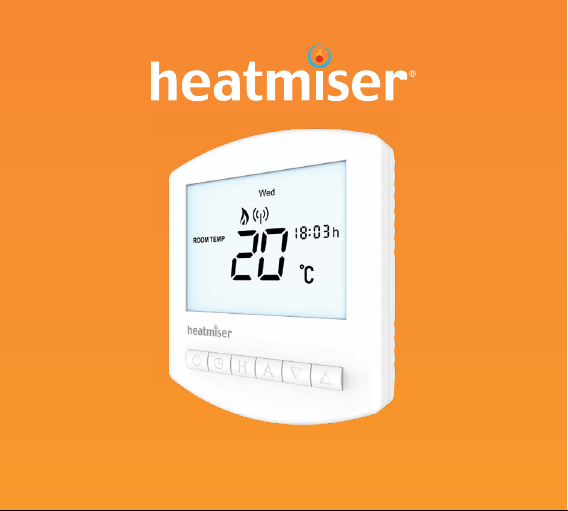
Heatmiser Slimline-RF User manual
Other Heatmiser Thermostat manuals

Heatmiser
Heatmiser PRT-UWTS User manual

Heatmiser
Heatmiser PRTHW-TS User manual

Heatmiser
Heatmiser DT-B User manual

Heatmiser
Heatmiser PRT-ETS WiFi User manual

Heatmiser
Heatmiser JG PRT-E User manual

Heatmiser
Heatmiser neo Stat-e User manual

Heatmiser
Heatmiser NetMonitor V3 Operation manual

Heatmiser
Heatmiser PRT-E1 User manual

Heatmiser
Heatmiser NeoAir V2-M User manual

Heatmiser
Heatmiser touch-n User manual

Heatmiser
Heatmiser smartstat User manual

Heatmiser
Heatmiser PRT-ETS User manual

Heatmiser
Heatmiser TM4-TS User manual

Heatmiser
Heatmiser Touch-RF User manual

Heatmiser
Heatmiser neoStat-hw V2 User manual

Heatmiser
Heatmiser PRT-W User manual

Heatmiser
Heatmiser PRT-EAU1 User manual

Heatmiser
Heatmiser DT User manual

Heatmiser
Heatmiser Wireless Series User manual

Heatmiser
Heatmiser TouchScreen Series User manual


Popular Thermostat manuals by other brands


Charmeg
Charmeg MP-R user manual

dixell
dixell WING XW40LS Installing and operating instructions

Network Thermostat
Network Thermostat NetX X7C-WIFI Installation and programming manual

Radio Thermostat
Radio Thermostat CT80 Operation guide

HAI
HAI Omnistat RC-120 installation manual

Lennox
Lennox iComfort E30 Installation and setup guide

Lux Products
Lux Products PSD011Ba Installation and operating instructions

Computherm
Computherm Q20 operating instructions

Mars
Mars HEAT CONTROLLER IR Wireless Thermostat user manual

LUX
LUX LP0511D user manual

Saswell
Saswell SAS920XWHB-7-S-RF User manual and warranty card

Aircalo
Aircalo TFP1-ET85P2 operating manual