3
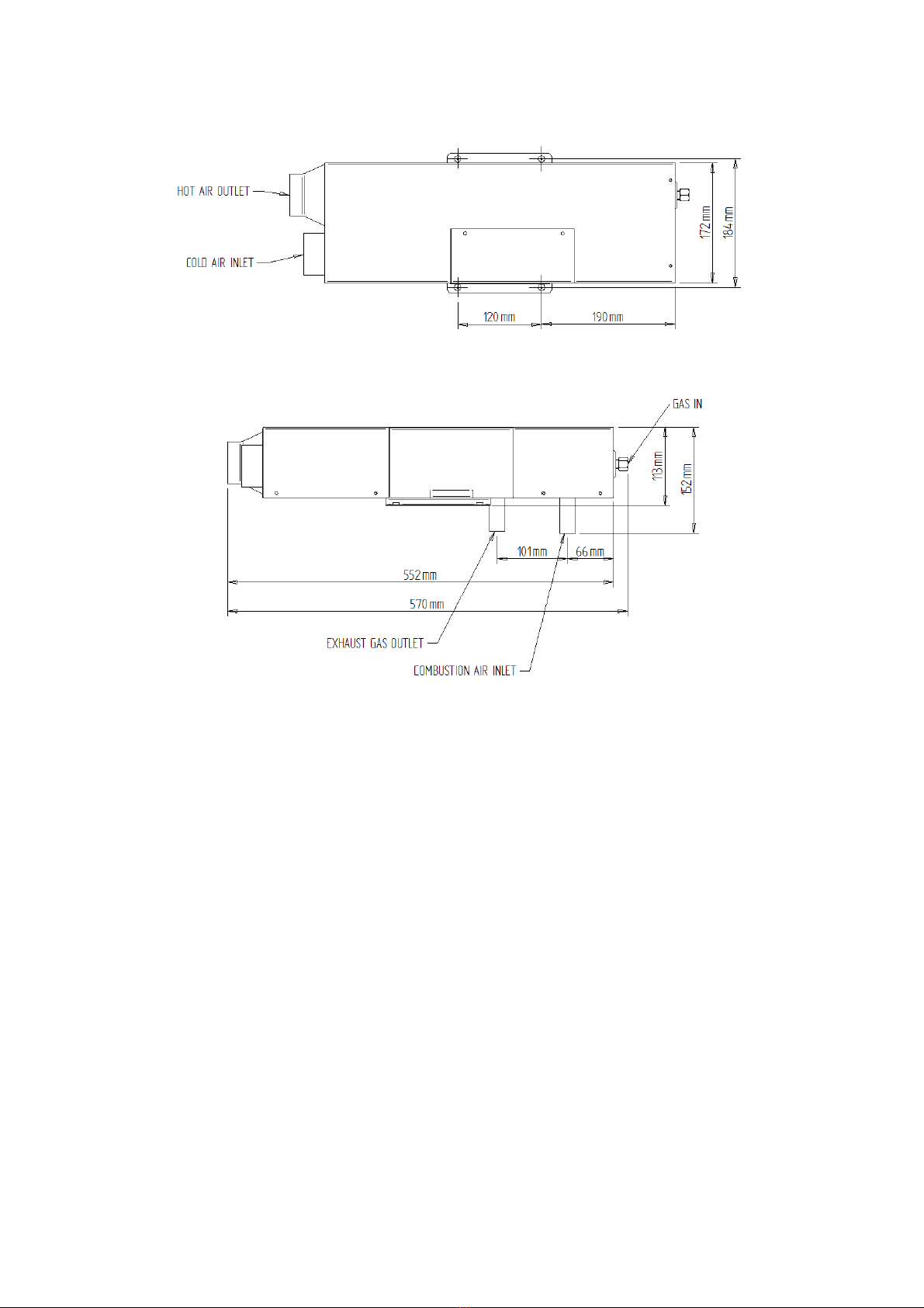
Ensure the position allows access for servicing the Space Heater and that there is a minimum of
25mm distance around the heater to adjacent walls when mounted inside the vehicle.
Propex’s policy is one of continuous improvement and we reserve the right to change specifications
without prior notice.
4. WARNINGS
The Propex Space Heater has been designed for caravan, motor home and mobile applications, and
is more than adequate for typical recreational vehicle use. The Propex Space Heater is designed to
be installed in conjunction with a ducted hot air system.
Observe all warnings.
In the unlikely event of leaks in the gas system, or if there is a smell of gas:
- Extinguish all naked flames
- Do not operate any electrical switches
- Turn off all gas appliances
- Open windows and doors for ventilation
- Do not smoke
- Shut off gas connection
Get the system thoroughly checked by a registered gas engineer.
-The space heater shall not be operated in the following situations:
•When refuelling the vehicle, the vehicle towing the caravan, or other appliances
•When the vehicle in which the heater is installed is in motion.
•When the vehicle in which the heater is installed is in a confined space such as a garage
This appliance is not intended for use by persons (including children) with reduced physical, sensory
or mental capabilities, or lack of experience and knowledge, unless they have been given supervision
or instruction concerning use of the appliance by a person responsible for their safety. Children
should be supervised to ensure that they do not play with the appliance.
Ensure that a minimum of one hot air outlet vent is permanently open at all times. This should ideally
be the first outlet and not more than approximately 1 metre from the heater.
Any alteration to the appliance, including flue components, use of non-Propex spare
parts/accessories and non-observation of the installation and operation instructions shall lead to
cancellation of the warranty and exclusion of liability claims and results in it becoming illegal to use
the appliance.
Please note that incorrect installation, misuse or use of non original Propex parts may invalidate the
warranty. It also becomes illegal to use the appliance if incorrectly installed, and in some countries
this even makes it illegal to use the vehicle.
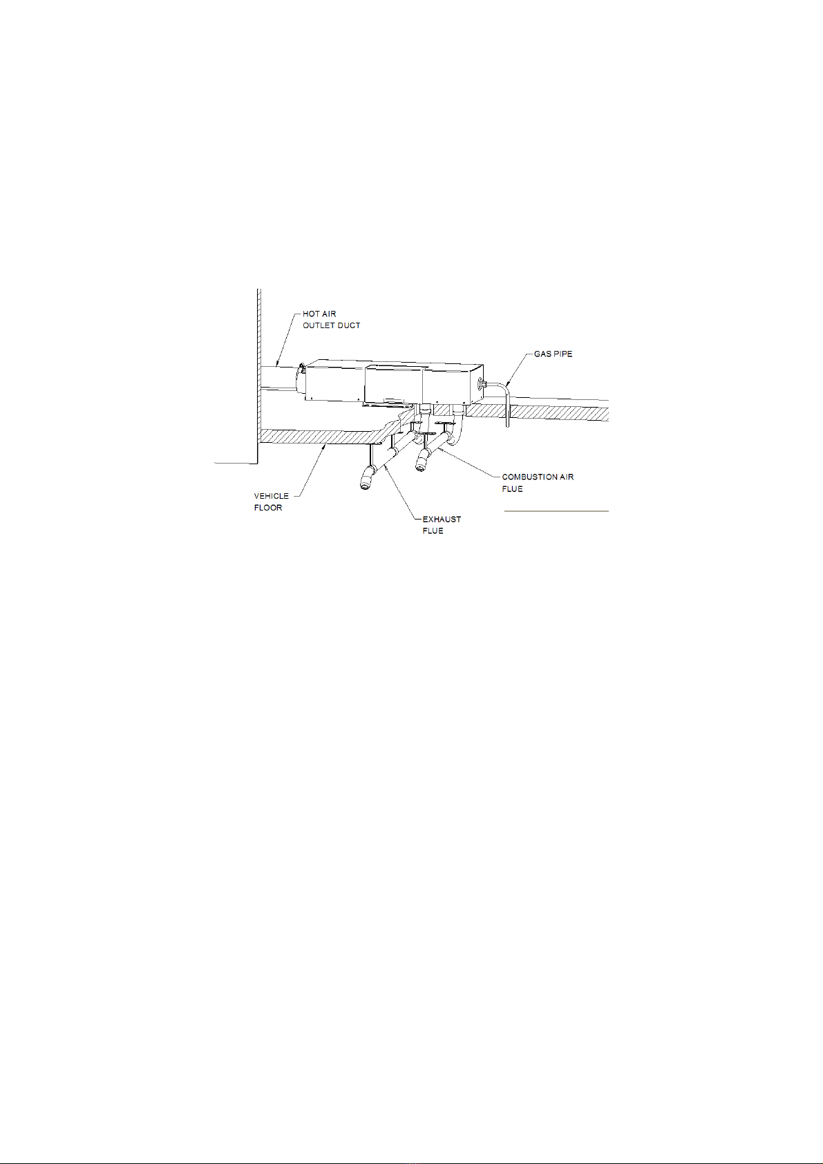
When operating using gas, the combustion air flue and outlet opening for the products of combustion
(exhaust flue) shall never be obstructed. They should be checked regularly, and if necessary cleaned
by the user (e.g. in winter, snow shall be removed from the combustion outlet and air intake).
This symbol indicates that this appliance is suitable for use in Leisure Accommodation Vehicles.
This symbol indicates that this appliance is suitable for use in boats when the correct flue
terminal is used.