HEIDELBERG Wallbox Energy Control User manual

Wallbox Energy Control, eng
Installation instructions
00.999.3040/


A Installation instructions
Installation instructions ................................................................................................................ A.1.1
1 Wallbox Energy Control assembly instructions ........................................................................ A.1.1
1.1 Safety ............................................................................................................................. A.1.1
1.2 Prerequisites .................................................................................................................. A.1.1
1.3 Checklist ........................................................................................................................ A.1.1
1.4 Scope of supply/accessories in the separate parts set .................................................. A.1.1
1.5 Mounting on the wall ...................................................................................................... A.1.2
1.6 Mounting on a column .................................................................................................... A.1.5
1.7 Electrical connection ...................................................................................................... A.1.5
1.8 Commissioning .............................................................................................................. A.1.9
1.9 Contact address/Customer Sales Representative ......................................................... A.1.10
1.10 Environment ................................................................................................................... A.1.10
Main chapter overview
00.999.3040/ A. 1

Main chapter overview
A. 2 00.999.3040/

Installation instructions
1 Wallbox Energy Control assembly instructions
1.1 Safety
Before installing and starting up the Wallbox, please
carefully read the enclosed safety instructions.
1.2 Prerequisites
● The Wallbox may only be operated when mount‐
ed vertically.
● If possible, the Wallbox should be mounted so
that it is not directly exposed to rain e.g. to pre‐
vent icing, being damaged by hail or similar. Do
not expose the Wallbox to direct sunlight be‐
cause this can cause it to overheat.
● The individual phases of the supply voltage must
each be protected with residual current devices
and circuit breakers.
● Single wires are not permitted to supply power.
● The diameter of the supply line must be between
9 mm and 17 mm.
● The charging current of the Wallbox must be set
in accordance with the building's circuit breakers.
(The procedure is described in the "Electrical
connection" section.)
Note
Please note that, depending on the local
installation location of the Wallbox, a
registration with the responsible network
operator can be necessary.
1.3 Checklist
The points listed below are essential for trouble-free
installation and start-up:
● Mechanical assembly,
● Electrical connection,
● Setting of the maximum charging current.
1.4 Scope of supply/accessories in the separate parts set
● Mounting plate with electronics housing,
● Wallbox housing cover,
● Safety instructions.
Bag 1:
● 4x fillister head screws M4x10 (to attach the
housing cover of the Wallbox),
● Cable gland ESKV25 (cable entry for power sup‐
ply),
● Gasket EADR25, for cable gland ESKV25.
Bag 2:
WB.000.3001-000UTKENU_02
Installation instructions
00.999.3040/ A.1.1

● Cable gland ESKV25 (cable entry for optional ex‐
ternal blocking device and optional RS485 bus),
● Gasket EADR25, for cable gland ESKV25,
● Multigasket for cable gland ESKV25,
● 2 blind plugs BS7 for multigasket.
1.5 Mounting on the wall
Note
The following drilling plan is not to scale.
It may not be used as a drilling template.
Please use only the specified dimen‐
sions from the drilling plan.
Installation instructions
A.1.2 00.999.3040/

210mm
105mm
260 mm
1
1
1
00.779.2712-000GRAUND_01
Fig. 1 Drilling plan for the Wallbox Energy Control
Prerequisites
Recommended mounting height above the floor is
1.00 m -1.10 m up to the lower hole.
The mounted Wallbox must be able to withstand a load
of at least 16 kg.
Installation instructions
00.999.3040/ A.1.3

Installation steps
1. Mark the three mounting holes (Fig. 1/1) as
shown on the drilling plan.
2. Drill and prepare the mounting holes according to
the type of mounting surface (e.g. dowels for ma‐
sonry). The screw diameter must not exceed
8 mm.
3. Screw in the two top fastening screws.
Note
The fastening screws are not included in
the scope of delivery due to the different
types of mounting surfaces.
1
2
WB.000.0004-000GRAUND_00
Fig. 2 Wallbox Energy Control, mounting plate
4. Hang the mounting plate (Fig. 2/1) of the Wallbox
on the two fastening screws (slotted holes,
Fig. 2/2).
5. Screw the third fastening screw into the lower
hole.
6. Tighten the three fastening screws (approx.
12 Nm).
Installation instructions
A.1.4 00.999.3040/

1.6 Mounting on a column
1
00.779.0000-000GRAUND_00
Fig. 3 Column with three attachment points
1. Hang the mounting plate of the Wallbox (Fig. /1)
on the three stud bolts of the column (Fig. 3/1).
2. Screw the three nuts (separate parts set for the
column) on the stud bolts (Fig. 3/1) and tighten
(approx. 12 Nm).
1.7 Electrical connection
Prerequisites
The Wallbox can be connected with a single phase
1 AC 230 V or with three phases 3 AC 400 V.
1
2
3
4
WB.000.0005-000GRAUND_00
Fig. 4 Wallbox Energy Control, open electronics
housing
1. Remove the four screws (Fig. 4/1) and take off
the cover of the electronics housing (Fig. 4/2).
2. Screw the cable gland ESKV25 (enclosed ac‐
cessories) with the respective gasket EADR25
(enclosed accessories) into the electronics hous‐
ing (Fig. 4/3) and tighten (approx. 8 Nm).
3. Strip off maximum 13 cm jacket from the power
supply cable.
4. Strip off approx. 11 to 13 mm insulation from the
individual wires.
5. Follow the instructions on the sticker (Fig. 4/4)
and then pierce the sticker on the cable entry.
6. Insert the connecting line into the cable gland.
7. Tighten the cap nut of the cable gland (approx.
4 Nm).
Installation instructions
00.999.3040/ A.1.5

N
1
L1
L2
L3
PE
00.779.2714-000GRAUND_00
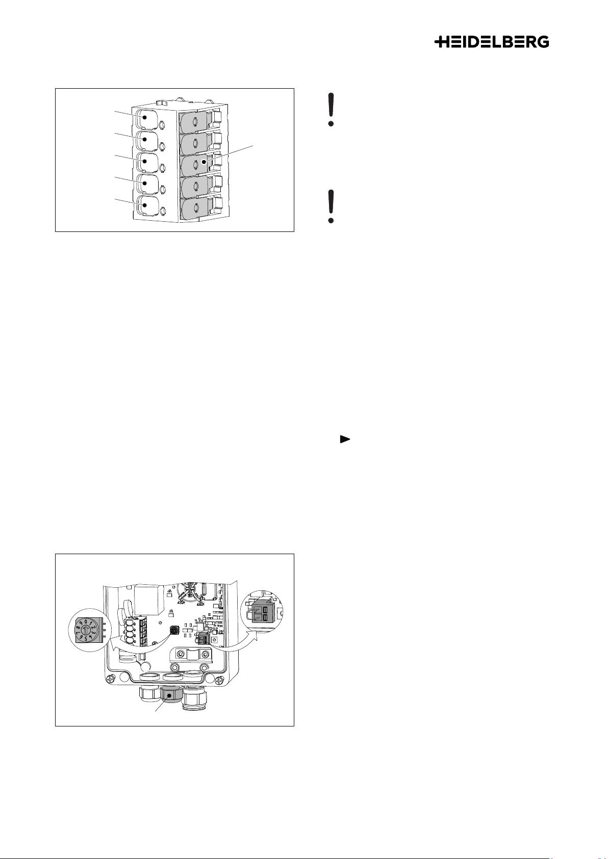
Fig. 5 Terminal clamps of the power supply unit
Caution - Heed the terminal sequence.
When clamping the connecting line,
heed the sequence of the terminals. PE,
L3, L2, L1, N.
Reverse polarity of the electrical con‐
necting lines will destroy the electronics
in the Wallbox!
Caution - Single-sided phase load
If in a system network of Wallboxes (with
load management), several vehicles
should be charged single-phased at the
same time, this can generate an unfa‐
vorable current distribution between the
phases.
Therefore, the Wallboxes must be con‐
nected with alternating phase sequence.
First Wallbox L1, L2, L3.
Second Wallbox L2, L3, L1.
Third Wallbox L3, L1, L2.
Fourth Wallbox again L1, L2, L3, etc.
8. Connect the individual wires of the power supply
cable as shown in the diagram (Fig. 5). If a single-
phase supply voltage is used, it must be con‐
nected to L1. Terminals L2 and L3 are not used
for a single-phase connection.
Note
This is a tool-free terminal strip. Folding
back the clamping lever (Fig. 5/1) opens
the terminal so that the respective indi‐
vidual wire can be inserted. The respec‐
tive clamping lever is then shut to secure
the respective individual wire. Folding
back more than one clamping lever at a
time must be avoided.
1
2
3
WB.000.0006-000GRAUND_00
Fig. 6 Opened electronics housing
Setting the charging current
The charging current of the Wallbox must be set in ac‐
cordance with the building's circuit breakers. Under no
circumstances may the charging current be set higher
than the respective circuit breaker.
The rotary switch (Fig. 6/1) is used to set the charging
current from 6 to 16 A.
06 A (default setting, delivery state)
18 A
210 A
312 A
414 A
5 ... 9 16 A
Installation instructions
A.1.6 00.999.3040/

External enabling/disabling of the Wallbox
The Wallbox can be optionally disabled or enabled by
means of external switching elements (e.g. key
switch). For this, the plug (Fig. 6/2) in the electronics
housing must be pulled out and the wire jumper re‐
moved. The now vacant contacts of the plug must then
be connected to a two-pole lead that exits through the
multigasket of the cable entry (Fig. 6/3) to the corre‐
sponding switching element.
The contacts of the switching element must be dimen‐
sioned so that they can switch zero-potential currents
of approx. 30 mA/12 V.
S6
S2 S3
S4 S5
WB.000.0023-000GRAUND_00
Fig. 7 Basic position of the microswitches
Basic position of the microswitches
The basic positions of the microswitches must not be
changed for Wallboxes in individual operation. The
microswitches are only configured for use in load/
energy management.
In the figure, you can see the basic position of the mi‐
croswitches.
Exception: S5/1, setting of the front illumination
The front illumination setting is made with the S5/1 mi‐
croswitch (Fig. 7).
The illumination behavior only affects status mes‐
sages.
Error messages always light up steadily.
This setting is only effective if a vehicle is connected.
S5/1
ON Front illumination lights up
steadily
OFF Front illumination goes out
after 5 min.
Tab. 1
Note
If an external switching element and/or
the load/energy management is used,
the blind plugs on the electronics hous‐
ing must be removed and the cable
gland with gasket installed, as well as
the multigasket (enclosed accessories)
(Fig. 6/3).
All remaining openings in the multigas‐
ket of the cable entry (Fig. 6/3) must be
sealed with the included blind plugs.
After inserting and connecting the ap‐
propriate lines, the cap nut of the cable
gland must be tightened (4 Nm).
Installation instructions
00.999.3040/ A.1.7

Load/energy management (optional)
The Wallbox "Energy Control" can be operated with
load/energy management. This way, the Wallbox can
be operated in various configurations, e.g.:
● Operation of several Wallboxes in a network with
monitoring of the power distribution (load man‐
agement),
● Operation of one or more Wallboxes with differ‐
ent types of energy supply, e.g. solar energy,
normal power network, ...
For additional information, read the online instructions
"Wallbox Energy Control, Local Load Management
and External Load Management":
https://wallbox.heidelberg.com/
If the Wallbox is operated in load/energy manage‐
ment, the communication lines (RS485 bus) must also
be laid through the multigasket of the cable gland
(Fig. 6/3).
9. Replace the lid of the electronics housing
(Fig. 4/2) and tighten the four screws (2.5 Nm).
1
1
1
2
WB.000.0007-000GRAUND_00
Fig. 8 Wallbox Energy Control with cover
10. Replace the cover, fasten it with the four screws
M4x10 (Fig. 8/1) and tighten them (1.8 Nm). The
four screws are included in the enclosed acces‐
sories.
Installation instructions
A.1.8 00.999.3040/

1.8 Commissioning
12
WB.000.0003-000GRAUND_00
Fig. 9 Wallbox Energy Control
1Front illumination
2Nameplate
1. Establish the power supply to the Wallbox.
As soon as the Wallbox is connected to the power
supply, the front illumination lights up for 5 minutes and
then goes out.
2. Connect the charging cable to the vehicle.
As soon as the charging cable is plugged into the ve‐
hicle, the Wallbox switches automatically to ready to
run state. The front illumination lights up.
If the vehicle requests the charging process, the Wall‐
box enables the charging process and the front illumi‐
nation pulses.
WB.000.0010-000GRAUND_00
Fig. 10 Status display "external block"
External block
If an external blocking device is used, when the vehicle
is connected, it checks whether there is an external
block (e.g. by means of a key switch or similar). As long
the external device has not enabled the Wallbox, the
front illumination lights up white with brief interruptions
(95% on, 5% off) and no charging takes place. After
the external device has enabled the Wallbox, the front
illumination lights up steady white until the vehicle re‐
quests the charging process.
Note
The procedure for fixing a malfunction
(various flashing sequences of the front
illumination) is described in the Wallbox
operating manual.
Installation instructions
00.999.3040/ A.1.9

1.9 Contact address/Customer Sales Representative
Hotline: +49 6222 82-2266
E-mail: [email protected]
Contact language: German and English.
Website: https://wallbox.heidelberg.com/
1.10 Environment
00.779.2716-000GRAUND_00
Fig. 11
This device is used for charging electrically powered
vehicles and is regulated by the corresponding EU Di‐
rective 2012/19/EU on waste electrical and electronic
equipment (WEEE).
Its disposal must comply with the national and regional
regulations for electrical and electronic equipment.
Waste equipment and batteries must not be disposed
of by putting them in household or bulky waste. The
device should be made inoperative before disposal.
Please dispose of the packaging material in the usual
collection containers for cardboard, paper, and plas‐
tics for your region.
Installation instructions
A.1.10 00.999.3040/
Table of contents
Other HEIDELBERG Batteries Charger manuals