HEIN-WERNER AUTOMOTIVE HW93657 Instructions for use

Operating Instructions & Parts Manual
Model Number
HW93657
HW93667
HW93660
HW93662
Service Jacks
HW93657/HW93660 HW93667/HW93662
Capacity
4 Ton
4 Ton Air/ Manual
10 Ton
10 Ton Air/ Manual
Made in
North America

Save These Instructions
For your safetyread,understand, andfollow the informationprovided withandon this jack. Theownerand operator of this
equipmentshallhaveanunderstandingofthisjackandsafe operating procedures before attempting to use. The owner and
operatorshallbeawarethatuse and repair of this product may require special skills and knowledge. Instructions and safety
informationshall be conveyed intheoperator's native language before useof this jack is authorized.If any doubt exists as
to the safe and proper use of this jack, remove from service immediately.
Inspect before each use. Do not use if there are broken, bent, cracked, or damaged parts (including labels). Any jack
thatappears damaged in anyway, operates abnormally, orismissing parts, shall beremoved from service immediately.If
thejack has been or is suspectedtohavebeen subjected to a shock load(aloaddropped suddenly, unexpectedly upon it),
immediately discontinue use until the jack has been checked by a Hein-Werner authorized service center. It is recom-
mended that an annual inspection be done by qualified personnel. Labels and Operator's Manual are available from
manufacturer.
PRODUCT DESCRIPTION
Hein-Werner Hydraulic Service Jacks are designed to lift,not sustain,rated capacity loads.Theyaredesignedtobe
used in conjunction with jack stands.Intended use: To lift one wheel or one axle of a vehicle for the purpose of service
and/orrepairof vehicle components. After lifting, loadsmustbeimmediatelysupported by appropriately rated jack
stands.Checkwithvehicle owner's manual for proper lift points.
DO NOT USE TO DOLLYORMOVEVEHICLE.
DONOTUSE FOR ANY PURPOSEOTHERTHAN THOSE USES OUTLINEDABOVE!
SPECIFICATIONS
SAFETY INSTRUCTIONS
BEFORE USE
1. Verify that the product and application are compatible, if in doubt callHein-Werner technical service.
2. Readtheoperator'smanualcompletelyand familiarizeyourselfthoroughlywiththeproduct,its componentsandrecognize
the potential hazards associated with its use before the use of this product.
3. Follow assembly instructions
4. Lower saddle fully.
5. Locateandremovetheairventscrew.
6. Ensure the oil level is within ~ 3/16" from the inner cylinder as viewed from the air vent screw hole.
7. Reinstallthe air vent screw.
8. Closereleasevalve by turning the release knob clockwise untilfirmresistanceisfelt.
9. Ensure that the jack rolls freely.
10.Raiseandlowertheunloadedsaddlethroughoutthe lift range before putting into service to ensurethepumpandrelease
valveoperate smoothly.
11. Replace worn or damaged parts and assemblies withHein-Werner Replacement Parts only. (See Replacement Parts
Section). Lubricate as instructed in Maintenance Section.
Min.Height Max.Height
5-1/4"
Capacity
26"
Model
5-1/4"
HW93657
Jack Size ( L x H )
4Ton
4Ton
26"
48-1/4"x 7-1/2"
HW93667
Air / Manual
HW93660
HW93662
Air / Manual
10Ton
10Ton
5-7/8"
5-7/8"
26"
26"
48-1/4"x 7-1/2"
53-3/8"x 9-3/4"
53-3/8"x 9-3/4"

•Study, understand, and follow all instructions
providedwith and on thisdevice before operating this
device.
•Do not exceed rated capacity.
•This is a lifting device only.
•After lifting, immediately transfer the load to
appropriately rated vehicle stands.
•Neverwork on, under, oraround a load supportedby
this device.
•Use only on hard, level surfaces capable of
sustaining rated capacity loads.
•Do not move or dolly loads with this device.
•Do not modify this device.
•Do not use adapters or accessories that are not
providedinitially.
•Lift only on areas of the vehicle as specified by the
vehiclemanufacturer.
•Failure to heed these markings may result in
personal injury and/or property damage.
!WARNING
ASSEMBLY
EQUIPMENTNEEDEDFORASSEMBLY:
1. Needle nose locking pliers
2. Snap-ring pliers (for:HW93657 andHW93667only)
3. 15/16“wrench(for: HW93660 andHW93662only)
4. Hammer
5. Tape measure
6. All necessary hardware is included and is assembled loosely onto the jack
ASSEMBLYINSTRUCTIONS:
1. Remove the service jack base and handle from the carton.
2. ForHW93657and HW93667, see figure 1 to removetheretainingring and the handle pivot pinfromthejack base that
connectsthrough the handle fork. ForHW93660and HW93662 (as shown infigure 2) remove the 5/16-18boltsand
the pin from the jack base that connects through the handle fork.
3. Removethe #6-32 screw and nutfromthe universal receptacle on top ofthehydraulic unit.
4. Pull the universal assembly, located on the bottom of the handle, out a minimum of 1-3/4".
5. Clamp the needle nose locking pliers onto the rod so that the universal assembly will not retract back into the handle.
6. Slide the universal assembly into the handle socket so that it extends out the other side.
7. Push the pivot pin that was removed in step 2 back through the handle and handle socket (may have to gently tap the
pinwithahammer).
8. Align the pivot pin with the holes on the side plates that the pivot pin was removed from and tighten the 5/16"-18 bolts
intothepivotpinuntil secure. (for HW93660andHW93662only)
9. Connecttheuniversal assembly to the universal receptacle rodusingthe#6-32 screw and nut from note 3(finger
tighten only).
10.Removetheneedle nose lockingpliers.
11. Jack is now operational and ready for use.
Helpful hint:
If the jack cover is a hindrance, it can be removed by using a 1/8" punch and taping out the pivot pins (be sure to attach
the cover back to the jack after assembly is completed).
!WARNING
To avoidcrushingand relatedinjuries:
NEVER work on, under or around a load supported
only by a jack. ALWAYS use adequately rated jack
stands.Immediately transfer the load toadequately
rated jack stands.
Besure all tools and personnel areclearbefore lowering
load. No alterations shall be made to this device. Only
attachmentsand/or adapters supplied by themanufac-
turer shall be used. Lift only on areas of the vehicle as
specifiedbythevehiclemanufacturer.

OPERATION
Lifting
1.Place the vehicle inthepark gear.
2. Engage the emergency brake.
3.Chock the wheels securely to preventinadvertentvehicle movement.
4.Locate and close the releasevalve by turning release knobclockwise,firmly.
5.Centerjacksaddleunderliftpoint.Refertothevehiclemanufacturerowner'smanualtolocateapprovedliftingpointson
thevehicle.
6. Verify lift point then use handle pump to contact lift point. To lift, pump handle until load reaches desired height.
7. Transfer the load immediately to appropriately rated jack stands.
Lowering
1. Raise load high enough to clear the jack stands.
2. Remove jack stands, carefully. (always used in pairs).
3. Slowly turn the release knob counterclockwise, but no more than 1/2 turn.If the load fails to lower:
a. Use another jack to raise the vehicle high enough to reinstall jack stands.
b.Remove the malfunctioning jackand then the jackstands.
c.Using the functioning jack, lowertheload by turning the operating handlecounterclockwise,but no more than 1/2 turn.
4.Push saddle down toreduceram exposure to rust andcontamination after removing the jackfromunder the load.
Figure3-HW93657/HW93660 Nomenclature Figure 4 -HW93667/HW93662Nomenclature
Lift Arm
Figure 1 - HW93657/ HW93667 Figure 2 - HW93660/ HW93662
Air Hose
Saddle
Handle Lift Arm
Handle Fork
Caster
Front Wheel
Release Knob
Saddle
Handle
Release Knob
Caster
Air Motor
Air Vent Screw
(on the power unit)
Air Vent Screw
(on the power unit)
Handle Fork
Lift Arm

TROUBLESHOOTING
MAINTENANCE
Important: Useonlya good grade hydraulic jack oil. Avoid mixing differenttypesoffluidandNever use brake fluid, turbine
oil, transmission fluid, motor oil or glycerin. Improper fluid can cause failure of the jack and the potential for sudden and
immediatelossof load. We recommend Hein-Werner hydraulicjackoilHW93291.
Adding oil
1.Lowersaddlefully.
2. Set jack in its upright, level position.
3.Locate and remove air ventscrew.
4. Fill with oil until ~3/16" above the inner cylinder as seen from theair vent screw hole.
5. Reinstall theair vent screw.
Changing oil
For best performance and longest life, replace the complete hydraulic fluid at least once a year.
1.Lowersaddlefully.
2.Removetheairvent screw.
3. Lay the jack on its side and drain the fluid into a suitable container.
Note: Disposeof hydraulic fluid inaccordance with local regulations.
4. Fill with oil until ~3/16" above the inner cylinder as seen from theair vent screwhole.
5. Reinstall theair vent screw.
Lubrication
Aperiodic coating of lightlubricating oil to pivotpoints, axles and hinges willhelp to prevent rustand assure
thatwheels,castors and pump assemblies move freely.
Cleaning
Periodically check the pump piston and ram for signs of rust or corrosion. Clean as needed and wipe with an oily cloth.
Note: Neverusesandpaper orabrasivematerialonthese surfaces!
Storage
Lower the saddle to its lowest position when not in use.
•Contact Hein-WernerTechnical Service
PossibleCauses Corrective Action
Jack will not lift load
Jackbleedsoffafter lift
Will not lift to full extension
• Release knob nottightly closed
•Overloadcondition
•Fluidlevellow
•Hydraulicunitmalfunction
• Ensure release knob tightly closed
• Remedy overload condition
•Ensureproper fluidlevel
Jackwillnotlowerafterunloading •Reservoiroverfilled
• Linkages binding
•Fluidlevellow
•Drain fluid to proper level
•Cleanandlubricatemoving parts
•Ensureproper fluidlevel
Symptom

Model HW93657 Replacement Parts
Figure 5 - Parts Illustration for Model HW93657

Figure6 - Parts Illustrationfor Model HW93657 (HydraulicUnit)
Model HW93657 Replacement Parts (cont.) - Hydraulic Unit

Model HW93657 Replacement Parts List
Part# Description Qty.
200003hGasket 1
200472 Screw 2
201110 Lockwasher 4
201479 Lockwasher 2
201733 Plug 1
201779 Lockwasher 2
201784 Lockwasher 1
201808 Rivet 2
203198hBall (7/32" O.D.) 1
203199hBall (1/4" O.D.) 1
203200hBall (9/32" O.D.) 1
203201hBall (5/16" O.D.) 1
203205hBall (7/16" O.D.) 1
203299 JamNut 4
203313 JamNut 2
203332 Nut 1
203344 JamNut 2
204270 Washer 2
204277 Washer 1
204301 Washer 1
204303 Washer 1
204343 Washer 4
204372 Washer 1
204444 Cotter Pin 3
204461 Cotter Pin 1
204842hCopper Gasket 1
209964 Lockwasher 2
210225 Spacer 1
210311 Pipe Plug 3
210411hWasher 1
211341 Rivet 1
212227 ReleaseValve 1
213152hPacking Ring 2
213171hPacking Ring 2
214538 GroovePin 4
214555hO-ring 1
214699 Bushing 1
214700 HandleSegment Assy.1
216645 Pin 1
216646 Pump Pin 1
218988 Roll Pin 1
219451 Hex Nut 2
220769 Cross Pin 1
221739hPoppet 1
221740 Ball Stop Plug(7/16" L)1
Part# Description Qty.
221742 Ball Stop Plug (3/4" L) 1
221764hRam Quad Ring 1
221766 Cylinder 1
221770 Low Pressure Pump 1
221771hWasher 1
221772hQuad ring 1
221778 Washer 4
221781 Handle and Cross Bar 1
221798 RetainerRing 4
221817 RetainerRing 2
221823 ParallelLink 2
221825 Parallel Link Pin 1
221829 Pin 1
221937 TurningKnob 1
221938 Roll Pin 1
222095 Release Stem Kit 1
222098 Speed Pump Assy. 1
222201hSpring 1
222257 Plug Poppet Valve 2
222533hScreen 2
223166hRam Screen 1
226314 GlandNut 1
226318 Grease Fitting 1
226319 Bellcrank Pin 1
226324 Pressure Plug 1
226325 Pump Link 2
226326 Nut 1
226327 Slotted Tube 1
226329 Pin 1
226331hSpring 1
226353hSpring 1
226366 Hex Head Bolt 1
226372 Spring 1
226615 Front Wheel 2
227395 PlungerAssy. 1
227397 Release Link 1
227399 Extension Rod 1
227436 TurningRod Assy. 1
228257hU-cup 1
228354 UniversalAssy. 1
228875 Spring 1
228881 Grip 2
229392 Serial Plate 1
229748hHeel Plate 3
229749 Washer 1
Part# Description Qty.
229750 Ram 1
229751 Pin 1
230583 Ram Assy. 1
231316 VentValve Assy. 1
231583 Rear Caster 2
231638 Filler Screw 1
231710 OilTank 1
232968hBack-up Washer 1
232969hU-cup 1
232970 Pressure Pump 1
232971 Pressure Pump Kit 1
233798 Tank Nut 1
233880 Tank Nut and Quad Ring1
233917hPlastic Spring 1
233921 Release Stem 1
234976 Cap Housing 1
241885 Bellcrank 1
241887 Handle Socket 1
241889 Liftcap 1
241893 SideplateAssy 1
241894 SideplateAssy 1
241895 Hydraulic Unit Cover 1
241907 RepairKit(Hyd.Unit) -
241956 Fulcrum Pin 1
241983 SideplateTieRod 2
241985 Support Rod 1
241986 FrontAxle 1
241987 Retainerring 2
241988 Handle Pivot Pin 1
241989 Extension Spring 2
241990 Handle Assy. 1
241991 Hydraulic Unit Casting 1
241993 HydraulicUnitAssy. 1
HW93657-K0 Label Kit (not shown)
HW93657-M0 Manual
hIncluded in Repair Kit 241907

Model HW93660 Replacement Parts
Figure 7 - Parts Illustration for Model HW93660
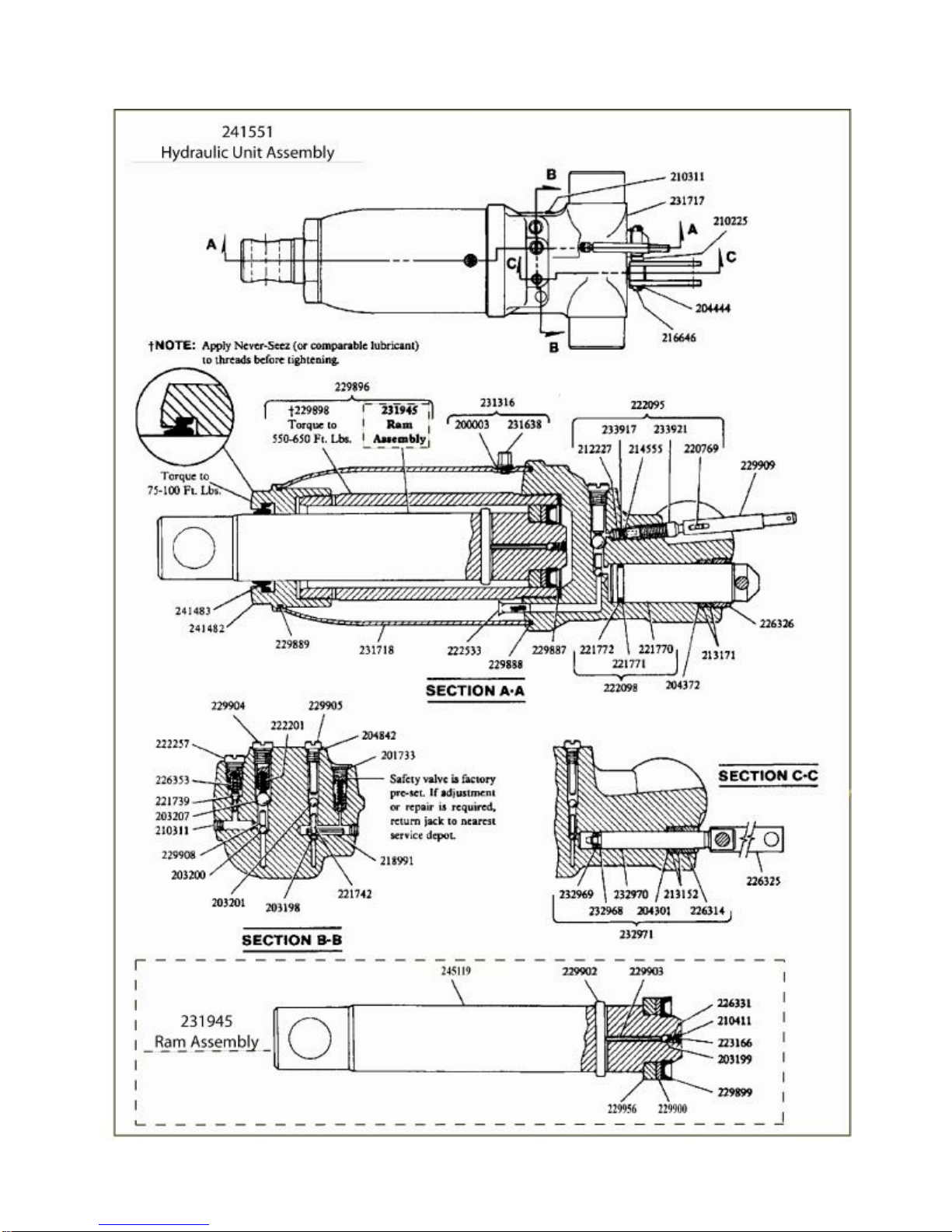
Model HW93660 Replacement Parts (cont.) - Hydraulic Unit
Figure8 - Parts Illustrationfor Model HW93660 (HydraulicUnit)

Model HW93660 Replacement Parts List
Part# Description Qty.
200003 Gasket 1
200472 Bolt 2
201110 Lockwasher 4
201115 Lockwasher 2
201481 Lockwasher 2
201733 Expansion Plug 1
201784 Lockwasher 1
201789 Lockwasher 2
203198hBall 1
203199hBall 1
203200hBall 1
203201hBall 1
203207hBall 1
203272 Nut 2
203297 Nut 2
203299 Nut 2
203323 Nut 2
203332 Nut 1
203344 Nut 2
204270 Washer 2
204277 Washer 1
204301 Washer 1
204303 Washer 1
204372 Washer 1
204444 Cotter Pin 4
204461 Cotter Pin 1
204842hGasket 1
207169 Nut 2
209964 Lockwasher 2
210225 Spacer 1
210311 Pipe Plug 3
210411hWasher 1
211341 Rivet 1
212227 ReleaseValve 1
212689 Bolt 2
213152hPacking Ring 2
213171hPacking Ring 2
214538 GroovePin 4
214555hO-ring 1
214699 Bushing 1
214700 Handle Segment 1
& Bushing
216645 Pin 1
216646 Pin 1
217653 Roll Pin 2
218988 Roll Pin 1
218991 Roll Pin 1
Part# Description Qty..
220769 Cross Pin 1
221739 Poppet 1
221742 Ball Stop Plug 1
221770 Speed Pump 1
221771hBack-up Washer 1
221772 Quad Ring 1
221781 Handle & Cross Bar 1
221809 HandleGrip 2
221937 Release Knob 1
221938 Roll Pin 1
222095 Release Stem Assy. 1
222098 Speed Pump Assy. 1
222201hSpring 1
222257 Plug 1
222533hScreen 2
223166hScreen 1
224253 Cover 1
226271 Fulcrum Pin 1
226314 GlandNut 1
226318 Grease Fitting 5
226325 Pump Link 2
226326 GlandNut 1
226331 Spring 1
226353hSpring 1
226366 Bolt 1
226372 PlungerSpring 1
227397 Link 1
227436 TurningRod Assy. 1
228875 Spring 1
229887hO-ring 1
229888hO-ring 1
229889hO-ring 1
229896 Ram & Cylinder Assy. 1
229898 Cylinder 1
229899hU-cup Packing 1
229900hBack-up Washer 1
229902 Cross Pin 1
229903 Pin 1
229904 Plug 1
229905 Plug 1
229908 Spacer 1
229909 Slotted Tube 1
229910 RetainingRing 2
229911 RetainingRing 2
229912 Washer 4
229913 Bell Crank 1
229915 Front Wheel 2
Part# Description Qty.
229927 Cap Housing 1
229929 Bearing 1
229932 Spring 2
229933 Plate 2
229934 Pin 1
229937 Caster 2
229938 Pin 1
229939 FrontAxle 1
229946 Pin 1
229947 RetainingRing 4
229949 Handle Socket 1
229951 Extension rod 1
229952 PlungerAssy. 1
229956 Heel Plate 1
230006 Bumper Pin 1
230407 UniversalAssy. 1
231316 Filler Plug & Gasket Assy. 1
231419 Fulcrum Pin 1
231420 Bolt 2
231430 ParallelLink 2
231474 Bell Crank & Fittings 1
231638 Filler Plug & Vent Valve 1
231717 Base 1
231718 OilTank 1
231945 Ram Assy. 1
231962 Handle Assy. 1
231963 Front Wheel Assy. 2
232619 Lifting Cap 1
232620 SwivelPin 1
232968hBack-up Washer 1
232969hU-cup Packing 1
232970 Pressure Pump 1
232971 Pressure Pump & 1
Gland Packing Assy.
233917 Plastic Spring 1
233921 Release Stem 1
240616 RepairKit(Hyd.Unit) -
241482 Tank Nut 1
241483hSeal 1
241551 HydraulicUnitAssy. 1
244317 Pin 1
245119 Ram 1
HW93660-K0 Label Kit (not shown)
HW93657-M0 Manual
hIncluded in Repair Kit 240616
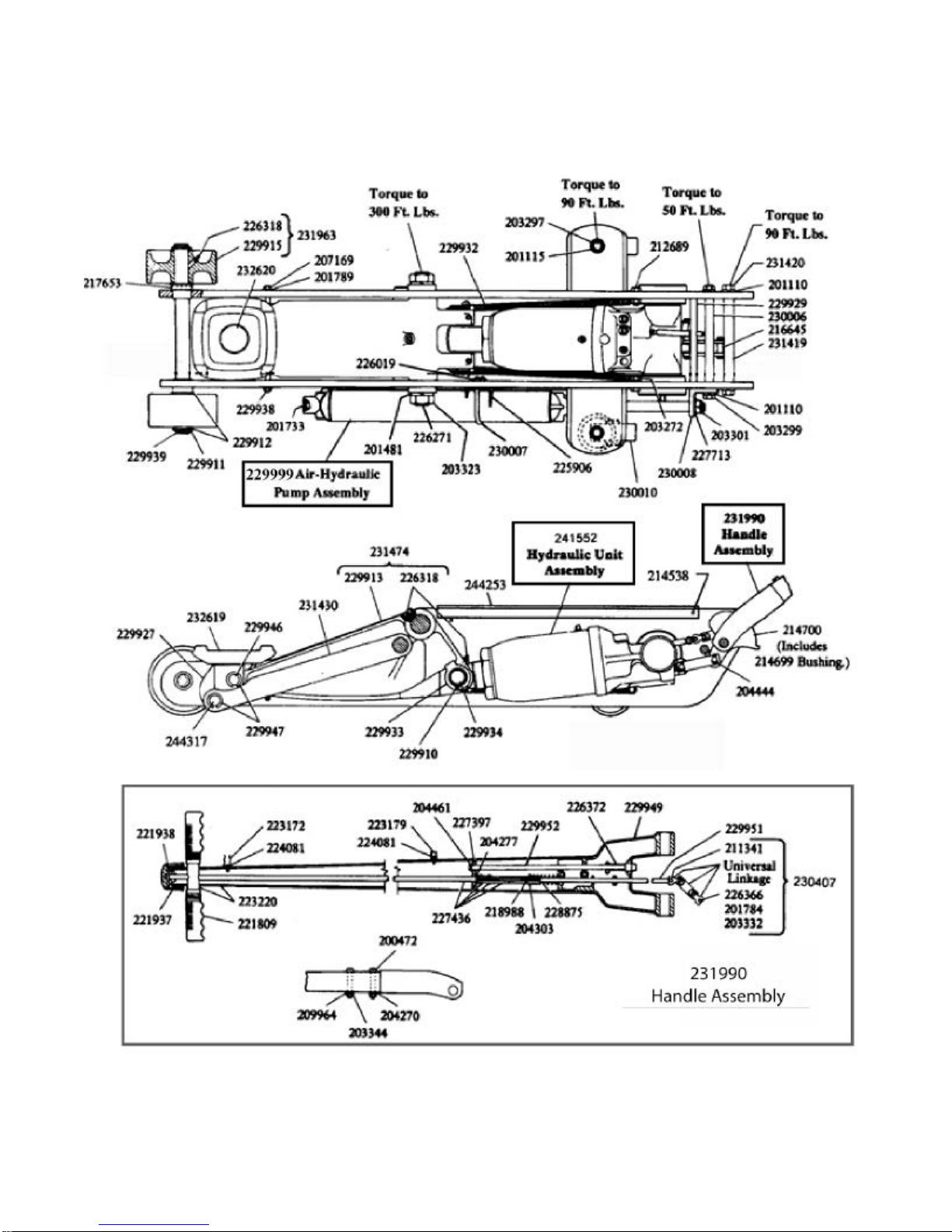
Model HW93662 Replacement Parts
Figure 9 - Parts Illustration for Model HW93662

Model HW93662 Replacement Parts (cont.) - Hyd. Unit
Figure10 - Parts Illustration for ModelHW93662(Hydraulic Unit)

Model HW93662 Replacement Parts (cont.) - Air Hyd. Pump
Figure 11- Parts Illustration forModel HW93662 (Air Hyd.Pump)
200003 Gasket 1
200472 Bolt 2
201110 Lockwasher 4
201115 Lockwasher 2
201481 Lockwasher 2
201733 Expansion Plug 1
201784 Lockwasher 1
201789 Lockwasher 2
203198hBall (7/32" O.D.) 1
203199hBall (1/4" O.D.) 1
203200hBall (9/32" O.D.) 1
203201hBall (5/16" O.D.) 1
203202 Ball (11/32" O.D.) 1
203207hBall 1
203272 Nut 2
203297 Nut 2
203299 Nut 2
203301 JamNut 1
203323 Nut 2
203332 Nut 1
203344 Nut 2
204270 Washer 2
204277 Washer 1
204301 Washer 1
204303 Washer 1
204372 Washer 1
204444 Cotter Pin 4
204461 Cotter Pin 1
204842hGasket 1
207169 Nut 2
209964 Lockwasher 2
210225 Spacer 1
210311 Pipe Plug 3
210411hWasher 1
211341 Rivet 1
212227 ReleaseValve 1
212689 Bolt 2
213152hPacking Ring 2
213171hPacking Ring 2
214538 GroovePin 4
Model HW93662 Replacement Parts List
Part# Description Qty
214555hO-ring 1
214699 Bushing 1
214700 Handle Segment & 1
Bushing
216645 Pin 1
216646 Pin 1
217653 Roll Pin 2
218988 Roll Pin 1
218991 Roll Pin 1
219861 O-ring 1
220769 Coss Pin 1
221013#U-cup Packing 1
221739 Poppet 1
221742 Ball Stop Plug 1
221770 Speed Pump 1
221771hBack-up Washer 1
221772 Quad Ring 1
221809 HandleGrip 2
221820 RetainingRing 2
221937 Release Knob 1
Part# Description Qty Part# Description Qty

Model HW93662 Replacement Parts List (Cont.)
221938 Roll Pin 1
222095 Release Stem Assy. 1
222098 Speed Pump Assy. 1
222201hSpring 1
222202 Elbow 1
222257 Plug 1
222288#O-ring 1
222533hScreen 2
223166hScreen 1
223172 Hose Clip 1
223173 ReturnSpring 1
223176 Cylinder,Air 1
223179 Hose Clip 2
223180 AirValve 1
223183 Plug 1
223184 Spring 1
223187#Valve & Plunger 1
223194 Spring & Cushion 1
223203 TripWasher 2
223220 Handle & Cross Bar 1
223678 Pump Packing & 1
Piston
223680 Screen 1
224021 Hose,Air 1
224081 Screw 2
224156 Spring 1
224469 Washer 1
225371 Rubber Cushion 1
225384 TripSpring 1
225906 Bracket, Speed pak 1
226153 Spring 1
226271 Fulcrum Pin 1
226314 GlandNut 1
226318 Grease Fitting 5
226325 Pump Link 2
226326 GlandNut 1
226331 Spring 1
226353hSpring 1
226366 Bolt 1
226372 PlungerSpring 1
226373 Adjusting Screw 1
226401 Spring 1
226450 End Block 1
226451 Set Screw 2
226483 PipeNipple 1
227397 Link 1
227436 TurningRod Assy. 1
227713 Lockwasher 1
228235 Cotter Pin 1
228813 Washer 1
228814#Gland Nut 1
228815#U-cup Packing 1
228816#Washer 1
228875 Spring 1
229754 Pin 1
229887hO-ring 1
229888hO-ring 1
229889hO-ring 1
229896 Ram & Cylinder Assy.1
229898 Cylinder 1
229899hU-cup Packing 1
229900hBack-up Washer 1
229902 Cross Pin 1
229903 Pin 1
229904 Plug 1
229905 Plug 1
229908 Spacer 1
229909 Slotted Tube 1
229910 RetainingRing 2
229911 RetainingRing 2
229912 Washer 4
229913 Bell Crank 1
229915 Front Wheel 2
229927 Cap Housing 1
229929 Bearing 1
229932 Spring 2
229933 Plate 2
229934 Pin 1
229938 Pin 1
229939 FrontAxle 1
229946 Pin 1
229947 RetainingRing 4
229949 Handle Socket 1
229951 Extension Rod 1
229952 PlungerAssy. 1
229956 Heel Plate 1
229999 Air Hyd. Pump Assy. 1
230000 PumpCylinder 1
230003 Back-up Washer 1
230005 GlandNut 1
230006 Bumper Pin 1
230007 U-bolt 1
230008 Bracket 1
230010 Caster 2
230011 Spacer 1
230407 UniversalAssy. 1
231316 Filler Plug & 1
Gasket Assy.
231347 Piston & Roll Pin 1
231419 Fulcrum Pin 1
231420 Bolt 2
231430 ParallelLink 2
231474 Bell Crank & Fittings 1
231572 Cylinder Cap 1
231604 Piston Assy. 1
231619 Rod, Pump 1
231638 Fillerplug & VentValve 1
231717 Base 1
231718 OilTank 1
231945 Ram Assy. 1
231963 Front Wheel Assy. 2
231990 Handle Assy. 1
232619 Lifting Cap 1
232620 SwivelPin 1
232968hBack-up Washer 1
232969hU-cup Packing 1
232970 Pressure Pump 1
232971 Pressure Pump & 1
Gland Packing Assy.
233110 Pump U-cup 1
233622 Screw 4
233897 Ring,Sealing 1
233917 Plastic Spring 1
233921 Release Stem 1
240564 Repair Kit (Air Pump) -
240616 RepairKit(Hyd.Unit) -
241482 Tank Nut 1
241483hSeal 1
241552 HydraulicUnitAssy. 1
244253 Cover 1
244317 Pin 1
245119 Ram 1
HW93662-K0 Label Kit (not shown)
HW93657-M0 Manual
hIncluded in Repair Kit 240616
#Included in Repair Kit 240564
Part# Description Qty Part# Description Qty Part# Description Qty

Model HW93667 Replacement Part
Figure12-PartsIllustrationforModelHW93667

Model HW93667 Replacement Parts (cont.) - Hyd. Unit
Figure13-Parts Illustration for Model HW93667 (Hyd. Unit)

Model HW93667 Replacement Parts (cont.) - Air Hyd. Pump
Figure 14 - Parts Illustration for Model HW93667 (Air Hyd. Pump)
Model HW93667 Replacement Parts List
Part# Description Qty Part# Description Qty Part# Description Qty
200003hGasket 1
200472 Screw 2
201110 Lockwasher 4
201479 Lockwasher 2
201733 Plug 1
201779 Lockwasher 2
201784 Lockwasher 1
201808 Rivet 2
203198hBall (7/32" O.D.) 1
203199hBall (1/4" O.D.) 1
203200hBall (9/32" O.D.) 1
203201hBall (5/16" O.D.) 1
203202 Ball (11/32" O.D.) 1
203205hBall (7/16" O.D.) 1
203299 JamNut 4
203313 JamNut 2
203332 Nut 1
203344 JamNut 2
204270 Washer 2
204277 Washer 1
204301 Washer 1
204303 Washer 1
204343 Washer 4
204372 Washer 1
204444 Cotter Pin 3
204461 Cotter Pin 1
204842hCopper Gasket 1
209964 Lockwasher 2
210225 Spacer 1
210311 Pipe Plug 4
210411hWasher 1
211341 Rivet 1
212227 ReleaseValve 1
213152hPacking Ring 2
213171hPacking Ring 2
213639 Bolt 1
214538 GroovePin 4
214555hO-ring 1
214699 Bushing 1
214700 Handlesegment Assy.1
216645 Pin 1
216646 Pump Pin 1
218988 Roll Pin 1
219451 Hex Nut 2
220769 Cross Pin 1
221013#U-cup Packing 1
221377 Roll Pin 1
221739hPoppet 1
221740 BallStopPlug (7/16" L)1
221742 Ball Stop Plug(3/4" L)1
221764hRam Quad Ring 1
221766 Cylinder 1
221770 Low Pressure Pump 1
221771hWasher 1
221772hQuad ring 1
221778 Washer 2
221798 RetainerRing 4
221817 RetainerRing 2
221820 RetainingRing 1
221823 ParallelLink 2

Model HW93667 Replacement Parts List (cont.)
Part# Description Qty Part# Description Qty Part# Description Qty
221825 Parallel Link Pin 1
221829 Pin 1
221937 TurningKnob 1
221938 Roll Pin 1
222088 ScreenAssembly 1
222095 Release Stem Kit 1
222098 Speed Pump Assy. 1
222201hSpring 1
222202 Elbow 1
222257 Plug Poppet Valve 2
222288#O-ring 1
222533hScreen 2
223166hRam Screen 1
223172 Hose Clip 1
223173 ReturnSpring 1
223179 Hose Clip 2
223180 AirValve 1
223183 Plug 1
223184 spring 1
223187#Valve & Plunger 1
223203 TripWasher 2
223213 GlandNut 1
223220 Handle & Cross Bar 1
223678 Pump Packing & 1
Piston
223680 Screen 1
224034 Air Cylinder 1
224038 PumpRod 1
224081 Screw 3
224156 Spring 1
224344 Ball Stop Plug 1
224414 RetainingRing 1
224469 Washer 1
225371 Rubber Cushion 1
225384 TripSpring 1
225906 Bracket, Speed pak 1
226019 Lock Nut 4
226153 Spring 1
226314 GlandNut 1
226318 Grease fitting 1
226319 Bellcrank Pin 1
226324 Pressure Plug 1
226325 Pump Link 2
226326 Nut 1
226327 Slotted tube 1
226329 Pin 1
226331hSpring 1
226353hSpring 1
226366 Hex Head Bolt 1
226372 Spring 1
226373 Adjusting Screw 1
226450 End block 1
226451 Set Screw 2
226483 PipeNipple 1
226615 Front Wheel 2
227052 Washer 1
227395 PlungerAssy. 1
227397 Release Link 1
227399 Extension Rod 1
227436 TurningRod Assy. 1
228235 Cotter Pin 1
228257hU-cup 1
228354 UniversalLinkage 1
228813 Washer 1
228814#Glant Nut 1
228815#u-cup Packing 1
228816#Washer 1
228875 Spring 1
228881 Grip 2
229392 Serial plate 1
229748hHeel Plate 3
229749 Washer 1
229750 Ram 1
229751 Pin 1
229754 Extension tube 1
230003hBack-up Washer 1
230007 U-bolt 1
230430 Air Hose Assy. 1
230583 Ram Assy. 1
230753 Suction Tube 1
231316 VentValve Assy. 1
231572 Cylinder Cap 1
231583 Rear Caster 2
231638 Filler Screw 1
231710 OilTank 1
232968hBack-up Washer 1
232969hU-cup 1
232970 Pressure Pump 1
232971 Pressure Pump Kit 1
233110 Pump U-cup 1
233798 Tank Nut 1
233880 Tank Nut and Quad 1
Ring
233917hPlastic Spring 1
233921 Release stem 1
234976 Cap Housing 1
236684 Piston 1
236685 Sealing ring 1
240564 Repair Kit (Hyd. Pump) 1
241780 Handle 1
241885 Bellcrank 1
241887 Handle Socket 1
241889 Liftcap 1
241894 SideplateAssy 1
241895 Hydraulic Unit Cover 1
241907 RepairKit(Hyd.Unit)-
241955 SideplateAssy 1
241956 Fulcrum Pin 1
241983 SideplateTieRod 2
241985 Support Rod 1
241986 FrontAxle 1
241987 Retainerring 4
241988 Handle Pivot Pin 1
241989 Extension spring 2
241992 Hydraulic Unit Casting1
241994 HydraulicUnitAssy. 1
242160 Air Hyd. Pump Assy. 1
242161 PumpCylinder 1
243098 U-bolt 1
243101 Sleeve 1
HW93667-K0 Label Kit (not shown)
HW93657-M0 Manual
hIncluded in Repair Kit 241907
#Included in Repair Kit 240564
This manual suits for next models
3
Table of contents


