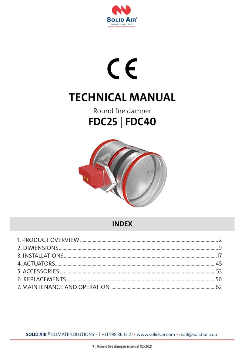
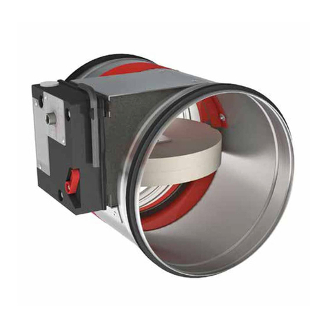
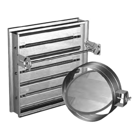
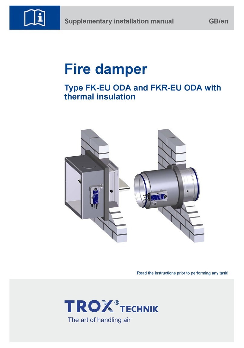
Helios BRK User manual

Bypassregelklappe
Bypass control damper
Registre de réglage
BRK
Helios Ventilatoren
MONTAGE- UND BETRIEBSVORSCHRIFT
INSTALLATION AND OPERATING INSTRUCTIONS
NOTICE DE MONTAGE ET D’UTILISATION FR
EN
DE

DEUTSCH
Bypassregelklappe BRK 1000x1000
Montage- und Betriebsvorschrift
Inhaltsverzeichnis
KAPITEL 1 ALLGEMEINE HINWEISE ������������������������������������������������������������������������������������ SEITE 2
1.1 Wichtige Informationen..................................................................................................... Seite 2
1.2 Warn- und Sicherheitshinweise ....................................................................................... Seite 2
1.3 Garantieansprüche – Haftungsausschluss........................................................................ Seite 2
1.4 Einsatzbereich – Bestimmungsgemäße Verwendung........................................................ Seite 2
1.5 Funktionsbeschreibung .................................................................................................... Seite 2
1.6 Abmessungen Bypassregelklappe BRK 1000x1000......................................................... Seite 3
KAPITEL 2 INSTALLATION UNDINBETRIEBNAHME������������������������������������������������������������ SEITE 3
2.1 Allgemeine Montagehinweise ........................................................................................... Seite 3
2.1.1 Sendungsannahme ................................................................................................... Seite 3
2.1.2 Einlagerung ............................................................................................................... Seite 3
2.1.3 Demontage und Wiederaufbau.................................................................................. Seite 3
2.1.4 Entsorgung ............................................................................................................... Seite 3
2.2 Mechanische Montage..................................................................................................... Seite 3
2.2.1 Bypassregelklappe BRK 1000x1000 ......................................................................... Seite 4
KAPITEL 3 SERVICE UND WARTUNG ���������������������������������������������������������������������������������� SEITE 4
3.1 Service und Wartung........................................................................................................ Seite 4

2
Bypassregelklappe BRK 1000x1000
Montage- und Betriebsvorschrift
DE
1�1 Wichtige Informationen
Zur Sicherstellung einer einwandfreien Funktion und zur eigenen Sicherheit sind alle nachstehenden Vorschriften genau
durchzulesen und zu beachten. Im Wartungsteil sind wichtige Informationen und erforderliche Reinigungs- und War-
tungstätigkeiten aufgeführt. Die Reinigungs- und Wartungsarbeiten dürfen nur von qualifizierten Elektrofachkräften
durchgeführt werden. Das Kapitel „Installation und Inbetriebnahme“ mit wichtigen Installationshinweisen und Geräte-
grundeinstellungen richtet sich an den Fachinstallateur.
mDer Elektroanschluss muss bis zur endgültigen Montage allpolig vom Netz getrennt sein!
Dieses Gerät ist nicht für den Gebrauch durch Personen (einschließlich Kinder) mit eingeschränkter körper-
licher, sensorischer oder geistiger Leistungsfähigkeit oder mangelnder Erfahrung und Kenntnis bestimmt, es
sei denn, sie wurden von einer für ihre Sicherheit verantwortlichen Person beaufsichtigt oder unterwiesen�
Kinder sollten beaufsichtigt werden, um sicherzustellen, dass sie nicht mit dem Gerät spielen�
Die Montage- und Betriebsvorschrift als Referenz am Gerät aufbewahren. Nach der Endmontage muss dem Betreiber
(Mieter/Eigentümer) das Dokument ausgehändigt werden.
1�2 Warn- und Sicherheitshinweise
Nebenstehendes Symbol ist ein sicherheitstechnischer Warnhinweis� Alle Sicherheitsvorschriften bzw� Symbole
müssen unbedingt beachtet werden, damit jegliche Gefahrensituation vermieden wird�
m GEFAHR
Warnung vor Gefahren, die bei Missachtung der Maßnahmen unmittelbar zu Tod oder schweren Verletzungen
führen.
m WARNUNG
Warnung vor Gefahren, die bei Missachtung der Maßnahmen zu Tod oder schweren Verletzungen führen können.
m VORSICHT
Warnung vor Gefahren, die bei Missachtung der Maßnahmen zu Verletzungen führen können.
ACHTUNG
Warnung vor Gefahren, die bei Missachtung der Maßnahmen zu Sachschäden führen können.
1�3 Garantieansprüche – Haftungsausschluss
Wenn die nachfolgenden Ausführungen nicht beachtet werden, entfällt die Gewährleistung. Gleiches gilt für Haftungs-
ansprüche an den Hersteller.
Der Gebrauch von Ersatzteilen, die nicht von Helios empfohlen oder angeboten werden, ist nicht statthaft. Eventuell
auftretende Schäden unterliegen nicht der Gewährleistung.
1�4 Einsatzbereich – Bestimmungsgemäße Verwendung
Die Bypassregelklappe BRK 1000x1000 ist ausschließlich als Zubehör für Spül- und Rauchschutz-Druck-Regelsyste-
me bestimmt.
Zur bestimmungsgemäßen Verwendung gehört auch die Beachtung der Betriebsanleitung und die Anweisung des
Herstellers des Lüftungsgerätes bzw. Rauch-Schutz-Druck-Anlage, sowie der von Helios festgelegten Inspektions- und
Wartungsintervalle.
Ein bestimmungsfremder Einsatz ist nicht zulässig!
1�5 Funktionsbeschreibung
Die Bypassregelklappe BRK 1000x1000 ist eine Präzisionsregelklappe für Rauchschutz-Druck-Anlagen. Der 24 V DC-
Antrieb öffnet und schließt die Bypassregelklappe BRK 1000x1000 vollständig in ca. 1,5 Sekunden. Entsprechend
schneller kann jede beliebige Zwischenstellung angefahren werden. Zur Steuerung des Antriebs ist an der Lamellen-
klappe eine LON-Bus-Baugruppe verbaut.
KAPITEL 1
ALLGEMEINE HINWEISE
m GEFAHR
m
m GEFAHR
m WARNUNG
m VORSICHT
ACHTUNG

Bypassregelklappe BRK 1000x1000
Montage- und Betriebsvorschrift
DE
DE
3
1�6 Abmessungen Bypassregelklappe BRK 1000x1000
2�1 Allgemeine Montagehinweise
2�1�1Sendungsannahme
Die Sendung ist sofort bei Anlieferung auf Beschädigungen und Typenrichtigkeit zu prüfen. Falls Schäden vorliegen,
umgehend Schadensmeldung unter Hinzuziehung des Transportunternehmens veranlassen. Bei nicht fristgerechter
Reklamation gehen evtl. Ansprüche verloren.
2�1�2Einlagerung
Bei Einlagerung über einen längeren Zeitraum sind zur Verhinderung schädlicher Einwirkungen folgende Maßnahmen
zu treffen:
Schutz durch trockene, luft- und staubdichte Verpackung (Kunststoffbeutel mit Trockenmittel und Feuchtigkeitsindika-
toren). Der Lagerort muss erschütterungsfrei, wassergeschützt und frei von übermäßigen Temperaturschwankungen
sein. Schäden, deren Ursprung in unsachgemäßem Transport, unsachgemäßer Einlagerung oder Inbetriebnahme lie-
gen, sind nachweisbar und unterliegen nicht der Gewährleistung.
2�1�3Demontage und Wiederaufbau
m Gefahr von Personen- und Sachschäden!
Die Demontage und der Wiederaufbau des Geräts gehören nicht zur routinemäßigen Wartung�
– Die Demontage und der Wiederaufbau des Geräts dürfen nur von qualifiziertem Fachpersonal durchgeführt werden.
2�1�4Entsorgung
m Lebensgefahr durch Stromschlag!
Ein Stromschlag kann zu Tod oder schweren Verletzungen führen�
– Sicherstellen, dass das Gerät spannungsfrei und isoliert ist. Gerät erden und kurzschließen, benachbarte spannungs-
führende Komponenten abschirmen.
Alle Komponenten müssen umweltgerecht, gemäß den örtlichen Vorschriften, Praktiken und Umweltvorschriften, ent-
sorgt werden.
Ein autorisierter Fachbetrieb für die Abfallbehandlung muss das Gerät oder die einzelnen Komponenten entsorgen. Der
beauftragte Auftragnehmer muss sicherstellen dass:
Die Komponenten nach Materialarten getrennt werden.
2�2 Mechanische Montage
mLebensgefahr durch Stromschlag!
Gefährdung durch elektrischen Schlag, bewegliche Teile�
Die Installation und der Anschluss des Geräts dürfen nur von qualifiziertem Fachpersonal durchgeführt werden. Die
elektrischen Anschlüsse müssen von einer Person durchgeführt werden, die über eine entsprechende Berufsausbil-
dung und Erfahrung in den einschlägigen Unfallverhütungsvorschriften sowie den allgemein anerkannten Sicherheits-
und Gesundheitsschutzvorschriften verfügt und berechtigt ist, Arbeiten am Gerät durchzuführen.
1287
1072
1036
1000
165
1287
1036
1000
1072
Abb�1
KAPITEL 2
INSTALLATION UND
INBETRIEBNAHME
m WARNUNG
m GEFAHR
m GEFAHR

Bypassregelklappe BRK 1000x1000
Montage- und Betriebsvorschrift
DE
DE
4
2�2�1Bypassregelklappe BRK 1000x1000
Vor allen Wartungs- und Installationsarbeiten oder vor Öffnen des Klemmenkastens ist das Gerät allpolig vom
Netz zu trennen! Der elektrische Anschluss darf nur von einer autorisierten Elektrofachkraft entsprechend den
nachstehenden Anschlussplänen ausgeführt werden� Der Elektroanschluss muss bis zur finalen Montage all-
polig vom Netz getrennt sein!
Gefahr von Sachschäden!
Die Bypassregelklappe BRK 1000x1000 könnte zerstört werden�
- Der Bypassregelklappen Antrieb darf nicht demontiert werden�
- Der elektrische Anschluss darf nur von einer Helios autorisierten Fachkraft durchgeführt werden�
Die Bypassregelklappe BRK 1000x1000 muss so montiert werden, dass sich der elektrische Anschlusskasten
und damit die Kabeleinführung an der Unterseite der Bypassregelklappe BRK 1000x1000 befinden�
1. Ggf. eine bauseitige Dichtung auf die Flanschoberfläche aufkleben.
2. Die Bypassregelklappe BRK 1000x1000 nun an einem entsprechenden Gegenflansch mit geeigneten Verbindungs-
material (Schrauben und Muttern) verschrauben (s. Abb. 3).
– Darauf achten, dass der 24 V DC-Antrieb seitlich positioniert ist.
– Der elektrische Anschluss muss durch eine Helios autorisierte Fachkraft hergestellt werden.
3�1 Service und Wartung
Reinigungs- und Wartungsarbeiten dürfen nur von einer Elektrofachkraft durchgeführt werden.
m Lebensgefahr!
Gefährdung durch elektrischen Schlag, bewegliche Teile�
Vor allen Wartungs- und Installationsarbeiten sowie vor Öffnen des Klemmenkastens ist das Gerät allpolig vom
Netz zu trennen!
Die Bypassregelklappe BRK 1000x1000 und der Stellantrieb müssen alle 6 Monate auf Schmutz überprüft werden.
m GEFAHR
ACHTUNG
HINWEIS
Abb�2
Abb�3
KAPITEL 3
SERVICE UND WARTUNG
m GEFAHR

Bypassregelklappe BRK 1000x1000
Montage- und Betriebsvorschrift
DE
DE
5
Leckverlust-Diagramm Abb�4 Druckbelastung Abb�5
Regelcharakteristik Abb�6 Druckverlust-Diagramm Abb�7

Bypassregelklappe BRK 1000x1000
Montage- und Betriebsvorschrift
DE
DE
6
Schall-Leistungs-Diagramm Abb�8 Widerstandsbeiwert Abb�9

ENGLISH
Bypass control damper BRK 1000x1000
Installation and Operating Instructions
Table of Contents
CHAPTER 1 GENERAL INFORMATION ��������������������������������������������������������������������������������� PAGE 2
1.1 Important information ...................................................................................................... Page 2
1.2 Warning and safety instructions ...................................................................................... Page 2
1.3 Warranty claims – Exclusion of liability ............................................................................. Page 2
1.4 Area of application – Intended use................................................................................... Page 2
1.5 Functional description...................................................................................................... Page 2
1.6 Dimensions Bypass control damper BRK 1000x1000...................................................... Page 3
CHAPTER 2 INSTALLATION AND COMMISSIONING ����������������������������������������������������������� PAGE 3
2.1 General installation instructions........................................................................................ Page 3
2.1.1 Receipt ....................................................................................................................... Page 3
2.1.2 Storage ....................................................................................................................... Page 3
2.1.3 Disassembly and re-assembly ..................................................................................... Page 3
2.1.4 Disposal ...................................................................................................................... Page 3
2.2 Mechanical assembly ...................................................................................................... Page 3
2.2.1 Bypass control damper BRK 1000x1000 ................................................................... Page 4
CHAPTER 3 SERVICE AND MAINTENANCE ������������������������������������������������������������������������� PAGE 4
3.1 Service and maintenance ................................................................................................ Page 4

2
Bypass control damper BRK 1000x1000
Installation and Operating Instructions
1�1 Important information
In order to ensure safety and correct operation and for your own safety, please read and observe the following inst-
ructions carefully before proceeding. Important information on filter changes and necessary cleaning and maintenance
activities is specified in the maintenance section. Filter changes are usually carried out by the user. Further cleaning and
maintenance work may only be carried out by qualified electricians. The chapter “Installation and commissioning” with
important installation information and basic unit settings is intended for the specialist installer.
mThe electrical connection must be fully isolated from the mains power supply until final assembly!
This unit is not intended for use by persons (including children) with reduced physical, sensory or mental
capabilities, or lack of experience and knowledge, unless they have been given supervision or instruction con-
cerning use of the unit by a person responsible for their safety� Children should be supervised to ensure that
they do not play with the unit�
Keep the installation and operating instructions with the unit for reference. The document must be handed to the ope-
rator (tenant/owner) after final assembly.
1�2 Warning and safety instructions
The adjacent symbol is a safety-relevant prominent warning label� All safety regulations and/or symbols must be
absolutely adhered to, so that any dangerous situation is avoided�
m DANGER
Indicates dangers which will directly result in death or serious injury if the safety instruction is not followed.
m WARNING
Indicates dangers which will result in death or serious injury if the safety instruction is not followed.
m CAUTION
Indicates dangers which can result in injuries if the safety instruction is not followed.
ATTENTION
Indicates dangers which can result in material damage if the safety instruction is not followed.
1�3 Warranty claims – Exclusion of liability
If the preceding instructions are not observed, all warranty claims shall be excluded. This also applies for liability claims
against the manufacturer.
The use of accessories, which are not recommended or offered by Helios, is not permitted. Any possible damages are
not covered by the warranty.
1�4 Area of application – Intended use
The bypass control damper BRK 1000x1000 is intended exclusively as an accessory for scavenging air systems and
smoke protection pressure control systems.
Intended use also includes the observance of operating instructions and the instructions from the manufacturer of the
ventilation unit and/or smoke protection pressure system, as well as the inspection and maintenance intervals specified
by Helios.
Any use other than the intended use is prohibited!
1�5 Functional description
The bypass control damper BRK 1000x1000 is a precision control damper for smoke protection pressure systems.
The 24 V DC drive opens and closes the bypass control damper BRK 1000x1000 fully in around 1.5 seconds. Accor-
dingly, any desired intermediate position can be reached faster. A LON bus module is fitted to the blade damper to
control the drive.
CHAPTER 1
GENERAL INFORMATION
m DANGER
m
m DANGER
m WARNING
m CAUTION
ATTENTION
EN

Bypass control damper BRK 1000x1000
Installation and Operating Instructions
EN
EN
3
1�6 Dimensions Bypass control damper BRK 1000x1000
2�1 General installation instructions
2�1�1Receipt
Please check delivery immediately on receipt for accuracy and damage. If damaged, please notify the carrier immedia-
tely. In case of delayed notification, any possible claim may be void.
2�1�2Storage
When storing for a prolonged time, the following steps are to be taken to avoid damaging influences:
Protection by dry, airtight and dust-proof packaging (plastic bag with desiccant and humidity indicators). The storage
place must be waterproof, vibration-free and free of temperature variations. Damages due to improper transportation,
storage or commissioning must be verified and are not liable for warranty.
2�1�3Disassembly and re-assembly
m Risk of personal injury and material damage!
The disassembly and re-assembly of the unit are not part of routine maintenance�
– The disassembly and re-assembly of the unit may only be carried out by a qualified specialist.
2�1�4Disposal
m Danger to life due to electric shock!
An electric shock can result in death or serious injury�
– Ensure that the unit is voltage-free and isolated from the mains power supply. Ground and short circuit the unit, shield
neighbouring live components.
All components must be disposed of in an environmentally-friendly manner in accordance with the local codes, practi-
ces and environmental regulations.
An authorised specialist waste processing company must dispose of the unit or the individual components. The appo-
inted contractor must ensure that:
The components are separated according to material types.
2�2 Mechanical assembly
mDanger to life due to electric shock!
Risk of injury due to electric shock, moving parts�
The installation and connection of the unit may only be carried out by qualified specialist personnel. The electrical con-
nections must be carried out by a person who has proper professional training and experience in the relevant accident
prevention regulations, as well as other generally recognised safety and occupational health codes, with authorisation
to perform work on the unit.
1287
1072
1036
1000
165
1287
1036
1000
1072
Fig�1
CHAPTER 2
INSTALLATION AND
COMMISSIONING
m WARNING
m DANGER
m DANGER

Bypass control damper BRK 1000x1000
Installation and Operating Instructions
EN
EN
4
2�2�1Bypass control damper BRK 1000x1000
The unit must be fully isolated from the mains power supply before all maintenance and installation work and
opening the terminal compartment! The electrical connections must be carried out in accordance with the
relevant wiring diagram and must only be carried out by qualified electricians� The electrical connection must
be fully isolated until the final assembly!
Risk of material damage!
There is a risk of the bypass control damper BRK 1000x1000 bring destroyed�
- The bypass control damper drive must not be dismantled�
- The electrical connection may only be carried out by a specialist authorised by Helios�
The bypass control damper BRK 1000x1000 must be installed so that the electrical terminal box and cable
entry point are located on the underside of the bypass control damper BRK 1000x1000�
1. Affix an on-site seal to the flange surface, if necessary.
2. Screw the bypass control damper BRK 1000x1000 to a corresponding counter flange with suitable connection
material (nuts and bolts) (see Fig. 3). .
– Ensure that the 24 V DC drive is positioned at the side.
– The electrical connection must be carried out by a specialist authorised by Helios.
3�1 Service and maintenance
Cleaning and maintenance work may only be carried out by an electrician.
m Danger to life!
The unit must be fully isolated from the mains power supply before all maintenance and installation work and
opening the terminal compartment!
Danger of electric shock, moving parts�
The bypass control damper BRK 1000x1000 and the actuator must be checked for dirt every 6 months.
m DANGER
Fig�2
Fig�3
CHAPTER 3
SERVICE AND
MAINTENANCE
m DANGER

Bypass control damper BRK 1000x1000
Installation and Operating Instructions
EN
EN
5
Leakage loss diagram Fig�4 Pressure load Fig�5
Control characteristics Fig�6 Pressure loss diagram Fig�7

Bypass control damper BRK 1000x1000
Installation and Operating Instructions
EN
EN
6
Sound power diagram Fig�8 Drag coefficient Fig�9

FRANÇAIS
Registre de réglage BRK 1000x1000
Notice de montage et d’utilisation
SOMMAIRE
CHAPITRE 1 INFORMATIONS GÉNÉRALES ������������������������������������������������������������������������ PAGE 2
1.1 Informations importantes .............................................................................................. Page 2
1.2 Précautions et consignes de sécurité ........................................................................... Page 2
1.3 Demandes de garantie – Réserves du constructeur...................................................... Page 2
1.4 Domaines d’utilisation – Utilisation conforme ................................................................ Page 2
1.5 Description des fonctionnalités ..................................................................................... Page 2
1.6 Dimensions du registre de réglage BRK 1000x1000 .................................................... Page 3
CHAPITRE 2 INSTALLATION ET MISE EN SERVICE������������������������������������������������������������ PAGE 3
2.1 Consignes de montage générales ................................................................................ Page 3
2.1.1 Réception de la marchandise ................................................................................... Page 3
2.1.2 Stockage ................................................................................................................. Page 3
2.1.3 Démontage et remontage ........................................................................................ Page 3
2.1.4 Mise au rebut ........................................................................................................... Page 3
2.2 Montage mécanique..................................................................................................... Page 3
2.2.1 Registre de réglage BRK 1000x1000 ....................................................................... Page 4
CHAPITRE 3 ENTRETIEN ET MAINTENANCE���������������������������������������������������������������������� PAGE 4
3.1 Entretien et maintenance .............................................................................................. Page 4

2
Registre de réglage BRK 1000x1000
Notice de montage et d’utilisation
FR
1�1 Informations importantes
Il est important de bien lire et suivre l’ensemble des consignes suivantes pour le bon fonctionnement de l’appareil et
pour la sécurité des utilisateurs. La section relative à l’entretien contient des informations importantes sur les activités
de nettoyage et d’entretien requises. Les travaux de nettoyage et d’entretien doivent être effectués exclusivement par
des électriciens qualifiés. Le chapitre « Installation et mise en service », qui contient des instructions d’installation impor-
tantes et les réglages de base de l’appareil, s’adresse aux installateurs professionnels.
mL’alimentation électrique doit être maintenue hors tension jusqu’à la fin de l’installation !
Cet appareil ne peut être utilisé par des personnes (y compris des enfants) dont les capacités phy-
siques, sensorielles ou mentales sont réduites ou qui manquent d’expérience ou de connais-
sances, sauf si elles sont surveillées ou formées par une personne responsable de leur sécurité�
Les enfants doivent être surveillés afin de garantir qu’ils ne jouent pas avec l’appareil�
Conserver la notice de montage et d’utilisation comme référence à proximité de l’appareil. Après le montage final, le
document doit être remis à l’utilisateur (locataire / propriétaire).
1�2 Précautions et consignes de sécurité
Les symboles ci-contre indiquent une consigne de sécurité� Toutes les consignes de sécurité ainsi que les
symboles doivent être impérativement respectés, afin d’éviter tout danger�
m DANGER
Mise en garde contre des dangers qui, en cas de non-respect des mesures, entraînent immédiatement la mort ou
de graves blessures.
m AVERTISSEMENT
Mise en garde contre des dangers qui, en cas de non-respect des mesures, peuvent entraîner la mort ou de graves
blessures.
m ATTENTION
Mise en garde contre des dangers qui, en cas de non-respect des mesures, peuvent entraîner des blessures.
ATTENTION
Mise en garde contre des dangers qui, en cas de non-respect des mesures, peuvent entraîner des dégâts matériels.
1�3 Demandes de garantie – Réserves du constructeur
Si les consignes figurant dans cette notice ne sont pas correctement respectées, la garantie s’annule. Il en est de
même pour toute implication de responsabilité du fabricant.
L’utilisation de pièces de rechange non conseillées ou proposées par Helios n’est pas permise. Les dégâts causés par
cette mauvaise utilisation ne sont pas inclus dans la garantie.
1�4 Domaines d’utilisation – Utilisation conforme
Le registre de réglage BRK 1000x1000 est un accessoire pour les systèmes de protection incendie par mise en sur-
pression (pour la protection contre les fumées).
L’utilisation conforme comprend le respect de la notice de montage et d’utilisation ainsi que des instructions du fabri-
cant des ventilateurs ou du système du contrôle de pression contre la fumée, ainsi que des intervalles d’inspection et
de maintenance spécifiés par Helios.
Tout usage inapproprié est interdit !
1�5 Description des fonctionnalités
Le registre de réglage BRK 1000x1000 permet de contrôler avec précision la pression dans les sytèmes de protection
incendie. Le servomoteur 24 V DC ouvre et ferme complètement le registre de réglage BRK 1000x1000 en 1,5 secon-
de environ. Toute position intermédiaire peut être approchée en conséquence plus rapidement. Le signal de pilotage du
servo-moteur se fait via une connection Modbus.
CHAPITRE 1
INFORMATIONS GÉNÉ-
RALES
m DANGER
m
m DANGER
m AVERTISSEMENT
m ATTENTION
ATTENTION

Registre de réglage BRK 1000x1000
Notice de montage et d’utilisation
FR
FR
3
1�6 Dimensions du registre de réglage BRK 1000x1000
2�1 Consignes de montage générales
2�1�1Réception de la marchandise
Dès réception, vérifier l’état et la conformité du matériel commandé. En cas de dégâts, les signaler immédiatement en
mentionnant le nom du transporteur. Attention, le non-respect de ces procédures peut entraîner le rejet de la réclama-
tion.
2�1�2Stockage
Pour un stockage de longue durée et pour éviter toute détérioration préjudiciable, il convient de se conformer aux
instructions suivantes :
Protéger avec un emballage sec, étanche à l’air et à la poussière (sac en matière synthétique contenant des sachets
déshydrateurs et un indicateur d’humidité). Stocker le matériel dans un endroit abrité de l’eau, exempt de vibrations et
de variations de températures excessives. Les dommages dus à de mauvaises conditions de transport ou de stockage
ou à une utilisation anormale sont décelables et ne sont pas couverts par la garantie.
2�1�3Démontage et remontage
m Risque de dommages corporels et matériels !
Le démontage et le remontage de l’appareil ne relèvent pas de la maintenance courante�
– Le démontage et le remontage de l’appareil doivent exclusivement être effectués par un personnel qualifié.
2�1�4Mise au rebut
m Danger de mort par choc électrique !
Un choc électrique peut causer la mort ou de graves blessures�
– S’assurer que l’appareil est hors tension et isolé. Mettre l’appareil à la terre, le court-circuiter et protéger les
composants adjacents sous tension.
Tous les composants doivent être éliminés dans le respect de l’environnement et conformément aux règles, aux pra-
tiques et aux réglementations environnementales locales.
L’élimination de l’appareil ou des différents composants doit être confiée à une entreprise agréée spécialisée dans le
traitement des déchets. L’entreprise mandatée doit garantir :
que les composants sont séparés en fonction des types de matériaux.
2�2 Montage mécanique
mDanger de mort par choc électrique !
Risque de choc électrique et risque lié aux pièces mobiles�
L’installation et le raccordement de l’appareil doivent exclusivement être effectués par un personnel qualifié. Le rac-
cordement électrique doit être réalisé par une personne dûment habilitée à intervenir sur l’appareil et disposant d’une
formation professionnelle et d’une expérience adéquates quant aux prescriptions applicables en matière de prévention
des accidents et aux règles reconnues en matière de sécurité et de santé.
1287
1072
1036
1000
165
1287
1036
1000
1072
Fig�1
CHAPITRE 2
INSTALLATION ET
MISE EN SERVICE
m AVERTISSEMENT
m DANGER
m DANGER

Registre de réglage BRK 1000x1000
Notice de montage et d’utilisation
FR
FR
4
2�2�1Registre de réglage BRK 1000x1000
Mettre impérativement l’appareil hors tension avant tous travaux d’entretien, d’installation ou avant l’ouverture
du boîtier électrique ! Le raccordement électrique doit être effectué par un électricien qualifié selon les
schémas de raccordement de cette notice� L’alimentation électrique doit être maintenue hors tension jusqu’à
la fin de l’installation !
Risque de dommages matériels !
Le registre de réglage BRK 1000x1000 pourrait être détruit�
- L’entrainement registre de réglage ne doit pas être démonté�
- Le raccordement électrique ne doit être effectué que par un spécialiste agréé par Helios�
Le registre de réglage BRK 1000x1000 doit être monté de manière à ce que le boîtier de raccordement élec-
trique et donc le passage des câbles se trouvent sur la face inférieure du registre de réglage BRK 1000x1000�
1. Si nécessaire, coller un joint sur la surface de la bride.
2. Visser maintenant le registre de réglage BRK 1000x1000 à une contre-bride correspondante avec le matériel de
raccordement approprié (vis et écrous) (voir Fig.3)
– S’assurer que le servo-moteur 24 V CC est positionné latéralement.
– Le raccordement électrique doit être effectué par un spécialiste agréé par Helios.
3�1 Entretien et maintenance
Les travaux de nettoyage et de maintenance doivent être effectués exclusivement par un électricien qualifié.
m Danger de mort !
Mettre impérativement l’appareil hors tension avant tous travaux d’entretien, d’installation et avant l’ouverture
du boîtier électrique !
Risque de choc électrique et risque lié aux pièces mobiles�
Tous les 6 mois, il convient de vérifier l’encrassement du registre de réglage BRK 1000x1000 et du servomoteur.
m DANGER
ATTENTION
REMARQUEREMARQUE
Fig�2
Fig�3
CHAPITRE 3
ENTRETIEN ET
MAINTENANCE
m DANGER

Registre de réglage BRK 1000x1000
Notice de montage et d’utilisation
FR
FR
5
Diagramme de fuite Fig�4 Charge de pression Fig�5
Courbe de réglage Fig�6 Diagramme de perte de charge Fig�7

Registre de réglage BRK 1000x1000
Notice de montage et d’utilisation
FR
FR
6
Diagramme de puissance sonore Fig�8 Coefficient de résistance Fig�9

Service und Information
DHELIOS Ventilatoren GmbH + Co KG · Lupfenstraße 8 · 78056 VS-Schwenningen FHELIOS Ventilateurs · Le Carré des Aviateurs · 157 avenue Charles Floquet · 93155 Le Blanc Mesnil Cedex
CH HELIOS Ventilatoren AG · Tannstrasse 4 · 8112 Otelfingen GB HELIOS Ventilation Systems Ltd. · 5 Crown Gate · Wyncolls Road · Severalls Industrial Park ·
AHELIOS Ventilatoren · Postfach 854 · Siemensstraße 15 · 6023 Innsbruck Colchester · Essex · CO4 9HZ
www.heliosventilatoren.de
Als Referenz am Gerät griffbereit aufbewahren! Druckschrift-Nr�
Please keep this manual for reference with the unit! Print-No�:
Conservez cette notice à proximité de l’appareil! N° Réf� 37 528-001/19-0265/V01/1021
Table of contents
Languages:
Other Helios Fire And Smoke Damper manuals
