Rf-t CR2 User manual

www.rft.be
en
Rf-Technologies nv Lange Ambachtstraat 40 9860 Oosterzele Belgium Tel +32 9 362 31 71 Fax +32 9 362 33 07 [email protected]
0749
C1-EN-M 06/2021
CR2
Circular re damper for large diameters

2Table of content
Table of content
Declaration of performance 4
Product presentation CR2 5
Range and dimensions CR2 5
Variant CR2-L500 5
Range and dimensions CR2-L500 6
Evolution - kits 6
Options - at the time of order 10
Storage and handling 11
Installation 11
Installation at a minimal distance from another damper or from an adjacent supporting construction 12
Installation in a rigid wall 13
Installation in rigid floor 15
Installation in flexible wall (metal stud gypsum plasterboard wall) 17
Installation in flexible wall (metal stud gypsum plasterboard wall), sealing with gypsum 19
Installation in flexible wall (metal stud gypsum plasterboard wall), sealing with mortar 21
Installation in gypsum block wall 23
Installation in flexible and rigid wall, sealing with rigid rock wool boards with coating 25
Installation in rigid floor, sealing with rigid rock wool boards with coating 28
Inspection of the damper 30
Operation and mechanisms 31
Electrical connection 36
Weights 38
Selection data 38
Example 39
Correction factor ΔL 39
Sample order 39
Approvals and certificates 40

3
Explanation of the abbreviations and pictograms
Wn = nominal width
Hn = nominal height
Dn = nominal diameter
E = integrity
I = thermal insulation
S = smoke leakage
Pa = pascal
ve = vertical wall penetration
ho = horizontal floor penetration
o -> i = meets the criteria from the outside
(o) to the inside (i)
i <-> o = fire side not important
V AC = Volt alternating current
V DC = Volt direct current
E.TELE = power supply magnet
E.ALIM = power supply motor
V = volt
W = watt
Auto = automatic
Tele = remote controlled
Pnom = nominal capacity
Pmax = maximum capacity
GKB (type A) / GKF (type F): “GKB”
stands for standard plasterboards (type
A according to EN 520) while “GKF”
plasterboards offer a higher fire resistance
for a similar plate thickness (type F
according to EN 520)
Cal-Sil = calcium silicate
OP = option (delivered with the product)
KIT = kit (delivered separately for repair or
upgrade)
PG = connection flange to the duct
Sn = free air passage
ζ [-] = pressure loss coefficient
Q = airflow
∆P = static pressure drop
v = air speed in the duct
Lwa = A-weighted sound power level
Lw oct = sound power level per octave
midband
dB(A) = A-weighted decibel value
∆L = correction factor
large dimensions
EN 1751
B/C
air tightness in accordance with EN 1751: class B (class C
in option )
suitable for built-in installation minimal distance allowed
BASTA OK
sealing with fire resistant stone wool boards allowed,
also for asymmetric opening

4Declaration of performance
I-06/2021CE_DoP_Rf-t_C1_EN
DECLARATION OF PERFORMANCE
Declarationofperformance
CE_DoP_Rf-t_C1_EN
I-06/2021
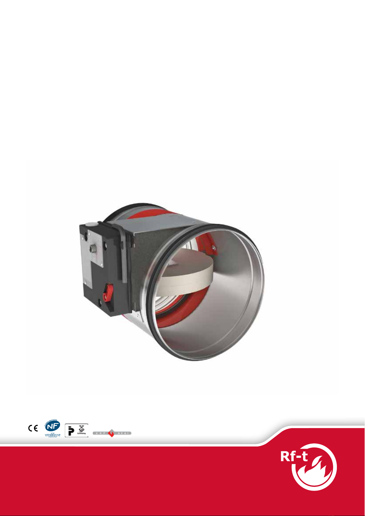
1. Unique identication code of the product-type: CR2
2. Intended use/es: Circular re damper to be used in conjunction with partitions to maintain re compartments in heating, ventilating and air conditioning
installations.
3. Manufacturer: Rf-Technologies NV, Lange Ambachtstraat 40, B-9860 Oosterzele
4. System/s of AVCP: System 1
5. Harmonised standard / European Assessment Document; notied body / European Technical Assessment, Technical Assessment Body,
notied body; certicate of constancy of performance:
EN 15650:2010, BCCA with identication number 0749; BCCA-0749-CPR-BC1-606-0464-15650.01-2517
6. Declared performance according to EN 15650:2010 (Fire resistance according to EN 1366-2 and classications according to EN 13501-3)
Essential characteristics Performance
Range Wall type Wall Sealing Installation Classication
Ø 200-630 mm Rigid wall Aerated concrete ≥ 100 mm Mortar / Gypsum 1 EI 120 (vei no) S - (500 Pa)
Stone wool + coating ≥ 140 kg/m³ 1 EI 90 (vei no) S - (300 Pa)
Stone wool Mulcol Multimastic SP + coating 1 EI 60 (vei no) S - (300 Pa)
Rigid oor Aerated concrete ≥ 150 mm Mortar 2 EI 120 (hoi no) S - (500 Pa)
Stone wool + coating ≥ 140 kg/m³ 2 EI 120 (hoi no) S - (300 Pa)
Flexible wall Metal studs gypsum plasterboard Type A (EN 520) ≥ 100 mm Stone wool ≥ 40 kg/m³ + cover plates 1 EI 60 (vei no) S - (500 Pa)
Gypsum 1 EI 60 (vei no) S - (500 Pa)
Stone wool + coating ≥ 140 kg/m³ 1 EI 60 (vei no) S - (300 Pa)
Metal studs gypsum plasterboard Type F (EN 520) ≥ 100 mm Stone wool ≥ 40 kg/m³ + cover plates 1 EI 90 (vei no) S - (300 Pa)
Gypsum 1 EI 120 (vei no) S - (500 Pa)
Mortar 1 EI 90 (vei no) S - (300 Pa)
Stone wool Mulcol Multimastic SP + coating 1 EI 60 (vei no) S - (300 Pa)
Stone wool + coating ≥ 140 kg/m³ 1 EI 90 (vei no) S - (300 Pa)
Paroc System Panel Sandwich panel type Paroc AST S ≥ 100 mm Hilti CFS-CT B 1S 3 EI 120 (vei no) S - (300 Pa)
Gypsum blocks ≥ 70 mm Block glue 1 EI 120 (vei no) S - (500 Pa)
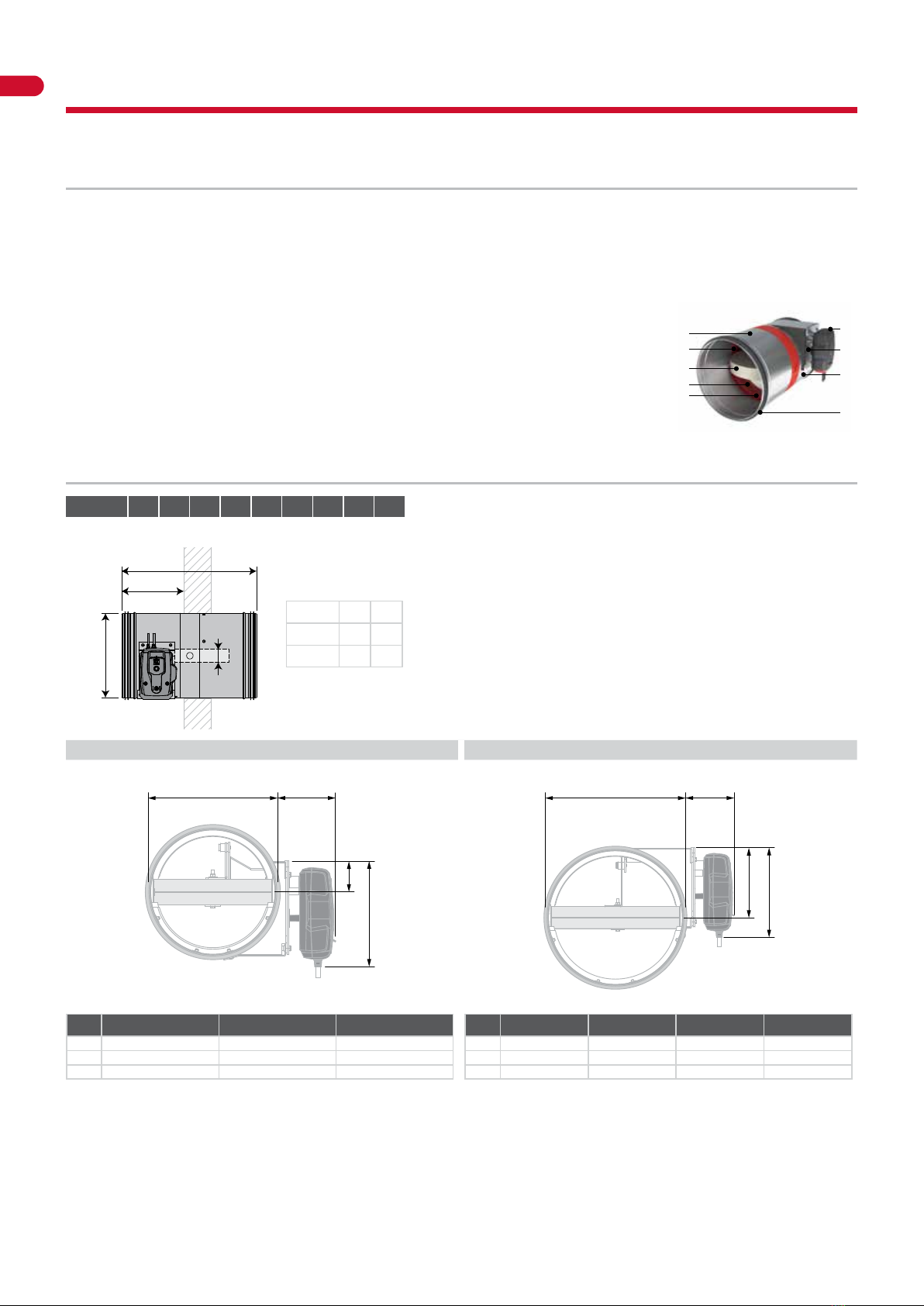
1 Type of installation: built-in,
0-360°. Minimal distances autho-
rised with axis till 45°.
≥ 30 mm
≤ 45°360° ≥ 30 mm 2 Type of installation: built-in,
0-360°. Minimal distances
authorised.
360° ≥ 30 mm ≥ 30 mm 3 Type of installation: built-in,
0/180° (CR)
≥ 30 mm ≥ 30 mm
Nominal activation conditions/sensitivity: Pass
Response delay (response time): closure time Pass
Operational reliability: cycling CFTH - 50 cycles; MANO - 300 cycles; B(L)F(T) - 10000 cycles; BFL(T) - 10000 cycles; BFN(T) - 10000 cycles; ONE - 10000 cycles; ONE-X - 10000 cycles; UNIQ - 10000 cycles
Durability of response delay: Pass
Durability of operational reliability: Pass
Protection against corrosion according to EN 60068-2-52: Pass
Damper casing leakage according to EN 1751: ≥ class B
Harmonised standard
EN 15650:2010
The performance of the product identied above is in conformity with the set of declared performance/s.This declaration of
performance is issued, in accordance with Regulation (EU) No 305/2011, under the sole responsibility of the manufacturer identi-
ed above.
Signed for and on behalf of the manufacturer by:
Mathieu Steenland, Technical Manager
Oosterzele, 06/2021

5
Product presentation CR2
Circular fire damper available in the largest dimensions (up to a diameter of 630 mm) with a fire resistance up to 120 minutes. Its
refractory tunnel is made of galvanised steel and its blade consists of asbestos-free panels, which are resistant to humidity.
Fire dampers are installed where air ducts penetrate fire-resistant compartment walls. Their role is to restore the fire resistance grade
of the penetrated wall and to prevent smoke propagation. Fire dampers are distinguished by their degree of fire resistance, by their
aeraulic properties as well as by their installation ease. Rf-Technologies’ fire dampers are all CE marked. They can be equipped with
various types of mechanisms depending on the specific needs linked to the project or to the local regulations.
5large dimensions
∎suitable for built-in installation
∎minimal distance allowed
∎suitable for rigid wall, rigid floor and light wall (metal stud
gypsum plasterboard wall, gypsum blocks)
∎sealing with fire resistant stone wool boards allowed, also for
asymmetric opening
∎air tightness in accordance with EN 1751: class B (class C in
option )
∎tested according to EN 1366-2 up to 500 Pa
∎operating mechanism outside the wall
∎maintenance-free
∎for indoor use
∎operating temperature: max. 50°C
EN 1751
B/C BASTA OK
1. casing in galvanised steel
2. damper blade
3. operating mechanism
4. sealing cold smoke
5. blade bumper
6. intumescent strip
7. fusible link
8. rubber sealing ring
9. product identification
1
2
4
5
6
7
8
3
9
Range and dimensions CR2
ØDn [mm] 200 250 315 355 400 450 500 560 630
Exceeding blade: X = on the mechanism side, Y = on the wall side
X375 Y
230
50
ØDn-2
145
ØDn [mm] 315 355 400 450 500 560 630
x - - - - - 15 50
y 24 44 66 91 116 146 181

6Range and dimensions CR2-L500
Variant CR2-L500
CR2 damper with a tunnel casing extension at the wall side to facilitate the connection to the duct when the supporting construction
is thicker than 100 mm.
1. casing in galvanised steel
2. damper blade
3. operating mechanism
4. sealing cold smoke
5. blade bumper
6. intumescent strip
7. fusible link
8. rubber sealing ring
9. product identification
1
2
4
5
6
8
3
9
7
Range and dimensions CR2-L500
ØDn [mm] 200 250 315 355 400 450 500 560 630
Exceeding blade: X = on the mechanism side, Y = on the wall side
230
500
ØDn-1
50
ØDn [mm] 560 630
x 15 50
y 21 56
ØDn < 315 mm ØDn ≥ 315 mm
ØDn P
Z
Q
ØDn P
Z
Q
CFTH ONE (X) BFL(T)
P81 105 101
Q182 199 110
Z58 60 80
CFTH ONE (X) BFL(T) BFN(T)
P85 105 104 104
Q182 199 110 110
Z156 157 179 179

7
Evolution - kits
Evolution - kits
KITS ONE T 24 FDCB Spring return actuator ONE 24V (with fusible link T) + bipolar beginning- and end-of-
range switch
KITS ONE T 24 FDCU Spring return actuator ONE 24V (with fusible link T) + unipolar beginning- and end-of-
range switch
KITS ONE T 230 FDCU Spring return actuator ONE 230V (with fusible link T) + unipolar beginning- and end-of-
range switch
KITS ONE T 230 FDCB Spring return actuator ONE 230V (with fusible link T) + bipolar beginning- and end-of-
range switch
KIT ONE-X 24 Spring return actuator ONE-X 24V (with fusible link T)
KIT ONE-X 230 Spring return actuator ONE-X 230V (with fusible link T)
KITS CFTH Automatic unlocking mechanism CFTH with FCU and without FTH 72
KITS BFL24 Spring return actuator BFL 24V
KITS BFL230 Spring return actuator BFL 230V

8Evolution - kits
KITS BFL24-ST Spring return actuator BFL 24V with plug (ST)
KITS BFLT24 Spring return actuator BFL 24V with thermo-electric fuse (T)
KITS BFLT230 Spring return actuator BFL 230V with thermo-electric fuse (T)
KITS BFLT24-ST Spring return actuator BFL 24V with thermo-electric fuse (T) and plug (ST)
KITS BFN24 Spring return actuator BFN 24V
KITS BFN24 Spring return actuator BFN 24V (BFN kits must be used instead of BFL kits for fire dampers
produced before 1/7/2015)
KITS BFN230 Spring return actuator BFN 230V
KITS BFN24-ST Spring return actuator BFN 24V with plug (ST)
KITS BFNT24 Spring return actuator BFN 24V with thermo-electric fuse (T)

9
Evolution - kits
KITS BFNT230 Spring return actuator BFN 230V with thermo-electric fuse (T)
KITS BFNT24-ST Spring return actuator BFN 24V with thermo-electric fuse (T) and plug (ST)
KITS BF24 Spring return actuator BF 24V (BF kits must be used instead of BFN kits for fire dampers
produced before 1/7/2015)
KITS FDC CFTH 1 limit switch (FCU/DCU/FCB/DCB)
KITS SN2 BFL/BFN Auxiliary limit switch ‘open/closed’
KITS FTH72 Fusible link FTH 72°C (for CFTH)
KITS ZBAT 72 Black spare part for thermo-electric fuse for BFLT/BFNT
FUS72 ONE Fusible link 72°C
MECT Testbox for mechanisms 24/48 V (magnet, motor, beginning and end of range switches)

10 Options - at the time of order
EPP CR2 Kit with 4 cover plates (gypsum plasterboard 12.5 mm) for CR2 in light wall.
INSPECAM
Sturdy digital endoscope for the internal inspection of fire dampers through an optional
inspection opening. The endoscope features a 1 meter long probe with a diameter of 8,2
mm equipped with a dimmable LED, a removable 4x zoom, a colour LCD monitor 3.5”.
Photographic capture 3MP and video capture 720P.
Options - at the time of order
UL Inspection opening to visually determine the state and the position of the damper, by
using an endoscope.
EN 1751
C
EN1751_C Air-tightness class C (note: for CU2 H > 600 or W > 800 / for CR2 Ø > 315).
ONE-X CN Connectors for the bus cables and the power cable.

11
Storage and handling
As this product is a safety element, it should be stored and handled with care.
Avoid:
• any kind of impact or damage
• contact with water
• deformation of the casing
It is recommended:
• to unload in a dry area
• not to flip or roll the product to move it
• not to use the damper as a scaffold, working table, etc.
• not to store smaller dampers inside larger ones
Installation
General points
∎The installation must comply with the installation manual and the classification report.
∎Axis orientation: see the declaration of performance.
∎Avoid obstruction of adjoining ducts.
∎Product installation: always with closed damper blade.
∎Verify if the blade can move freely.
∎Please observe safety distances with respect to other construction elements. The operating mechanism must also remain
accessible: allow for a clearance of 200 mm around the housing.
∎The air tightness class will be maintained if the damper is installed according to the installation manual.
∎Rf-t fire dampers are always tested in standardised constructions according to EN 1366-2. The achieved results are valid for similar
supporting constructions with a fire resistance, thickness and density equal or superior to the supporting construction used
during the test.
∎The damper must remain accessible for inspection and maintenance.
∎Schedule at least 2 visual checks each year.
2020
2021
2022
2023
2024
TEST
|
|
|
|
|

12 Installation
Installation at a minimal distance from another damper or from an adjacent supporting construction
≥ 75 mm
≥ 75 mm ≥ 200 mm ≥ 200 mm
≥ 30 mm ≥ 30 mm ≥ 200 mm
≥ 30 mm
1. Principle
According to the European test standard, a fire damper must
be installed at a minimum distance of 75 mm from an adjacent
wall and 200 mm from another damper, unless the solution was
tested at a shorter distance.
This range of Rf-t fire dampers has been successfully tested
and can be installed in a vertical or horizontal supporting
construction, at a distance below the minimum set by the
standard.
For circular dampers, the minimal distance is set to 30 mm.
A
B
2. Certified solution
For the Rf-t fire dampers, the solution consists of the following
elements: A: Universal sealing for minimal distance; B:
Sealing compliant with existing classifications (Declaration of
Performance).
A. Sealing of the opening at the side with minimal distances
between damper and wall/ceiling or another fire damper: rigid
stone wool panels (150 kg/m³) are applied to a depth of min.
400 mm, of which 150 mm on the mechanism side of the wall.
On the non-mechanism side of the wall, the stone wool panels
must be at least flush with the wall.
The surface of this sealing is set between the axes (centres) of
the dampers.
B. Sealing of the rest of the opening according to the existing
classifications for the fire damper (Declaration of Performance).
This also applies to circular dampers that are mounted at a
minimum distance from one another (30 to 200 mm) but at a
distance greater than 75 mm from a wall/ceiling.
Detailed information for each wall/sealing combination can be
found in the respective installation methods.
30 mm
30 mm
30 mm
200
mm
max 45°
max 45°
3. Restrictions
The orientation of the blade axis should be horizontal or
oriented at a maximum of 45°.
A maximum of 3 circular dampers can be installed at a
minimum distance from one another, both vertically and
horizontally (with a maximum cluster of 4 dampers).
Note: when sealing the opening with panels of fire resistant
stone wool, the maximum number of dampers also depends
on the maximum “blank seal” allowed for the selected sealing
material. Please refer to the manufacturer’s instructions for this
information.
1 2
3

13
Installation
Installation in a rigid wall
The product was tested and approved in:
Range Wall type Sealing Classication
Ø 200-630 mm Rigid wall Aerated concrete ≥ 100 mm Mortar / Gypsum EI 120 (vei no) S - (500 Pa)
Ø 200-630 mm Rigid wall Aerated concrete ≥ 100 mm Mortar / Gypsum EI 90 (vei no) S - (300 Pa)
230
375
≥100
≤ Dn+100 mm (300 Pa)
≤ Dn+80 mm (500 Pa)
≤ Dn+100 mm (300 Pa)
≤ Dn+80 mm (500 Pa)
Plaster /
Mortar
230
375
≥100
≤ Dn+100 mm (300 Pa)
≤ Dn+80 mm (500 Pa)
Plaster /
Mortar
TEST!
B < 200mm
≥ 30
50
50
≥ 30
50
50
B
≥ 30
4. The dampers can be installed at a minimum distance
(≥ 30 mm) from an adjacent wall or from another damper.
1 2
3 4

14 Installation
35%
≥100
5. Make the necessary openings (≤ Dn + 100 mm) /
(≤ Dn + 80 mm) in the wall.
400 mm
≥150 kg/m³
6. Mount the dampers in the opening.
Apply rigid stone wool panels (≥ 150 kg/m³) to a depth of
400 mm (150 mm on the mechanism side of the wall) to seal
the opening at the side with minimal distances.
The surface of this sealing is set between the axes (centres) of
the dampers.
Caution: the opening is sealed according to the existing
classification (see next point) when:
- 2 fire dampers are installed at a minimum distance from
one another but at a normal distance (≥ 75 mm) from the
wall or floor/ceiling.
- One single (no cluster) fire damper is located at a minimum
distance (≤ 75 mm) from a wall or floor/ceiling.
Plaster /
Mortar
7. Seal the rest of the opening with standard mortar or gypsum.
5 6
7

15
Installation
Installation in rigid floor
The product was tested and approved in:
Range Wall type Sealing Classication
Ø 200-630 mm Rigid oor Aerated concrete ≥ 150 mm Mortar EI 120 (hoi no) S - (500 Pa)
60%
≤ Dn+80 mm
≤ Dn+80 mm
≥ 150 mm
100 mm
230
375
Mortar
TEST!
B < 200mm
40
≥ 30
≥ 30
B
≥ 30
40
3. The dampers can be installed at a minimum distance
(≥ 30 mm) from an adjacent wall or from another damper.
≥ 150 mm
4. Make the necessary openings (≤ Dn + 80 mm) in the floor.
1 2
3 4

16 Installation
400 mm
≥150 kg/m³
5. Mount the dampers in the opening.
Apply rigid stone wool panels (≥ 150 kg/m³) to a depth of
400 mm (150 mm on the mechanism side of the wall) to seal
the opening at the side with minimal distances.
The surface of this sealing is set between the axes (centres) of
the dampers.
Caution: the opening is sealed according to the existing
classification (see next point) when:
- 2 fire dampers are installed at a minimum distance from
one another but at a normal distance (≥ 75 mm) from the
wall or floor/ceiling.
- One single (no cluster) fire damper is located at a minimum
distance (≤ 75 mm) from a wall or floor/ceiling.
Mortar
6. Seal the rest of the opening with standard mortar.
5 6

17
Installation
Installation in flexible wall (metal stud gypsum plasterboard wall)
The product was tested and approved in:
Range Wall type Sealing Classication
Ø 200-630 mm Flexible wall Metal studs gypsum plasterboard Type F (EN 520) ≥ 100 mm Stone wool ≥ 40 kg/m³ + cover plates EI 90 (vei no) S - (300 Pa)
Ø 200-630 mm Flexible wall Metal studs gypsum plasterboard Type A (EN 520) ≥ 100 mm Stone wool ≥ 40 kg/m³ + cover plates EI 60 (vei no) S - (500 Pa)
50
2x12.5 /
1x25 mm
Dn+50 mm
60’
90’
F (EN520)/GKF
A (EN520)/GKB
Dn+50 mm
≥ 40 kg/m³
≤ 625 mm
Dn+200 mm
230 mm
Dn+200 mm
Dn+5 mm
≥ 40 kg/m³
1.
3.
2.
M6
Plaster JointFiller
TEST!
A
A
A
A
≥ 30
≥ 30
B
A
A
AA
≥ 30
A 25 mm
B < 200 mm
≥ 30
≤ 625 mm 40 mm
5. The dampers can be installed at a minimum distance
(≥ 30 mm) from an adjacent wall or from another damper.
50
50
2x12.5 / 1x25 mm
≥ 40 kg/m³
6. Build the drywall and foresee horizontal and vertical studs
around the opening.
In the opening around the dampers (Dn + 50 mm), the void
between the gypsum boards is filled with stone wool with a
minimum density of 40 kg/m³.
1 2
3 4
5 6

18 Installation
400 mm
≥150 kg/m³
7. Mount the dampers in the opening.
Apply rigid stone wool panels (≥ 150 kg/m³) to a depth of
400 mm (150 mm on the mechanism side of the wall) to seal
the opening at the side with minimal distances.
Caution: the opening is sealed according to the existing
classification (see next point) when:
- 2 fire dampers are installed at a minimum distance from
one another but at a normal distance (≥ 75 mm) from the
wall or floor/ceiling.
- One single (no cluster) fire damper is located at a minimum
distance (≤ 75 mm) from a wall or floor/ceiling.
Dn+5 mm
Dn+200 mm
Plaster jointller
8. Apply cover plates (gypsum plasterboards) to finish the
surface at both sides.
Seal off the space between the plasterboards with jointfiller.
7 8

19
Installation
Installation in flexible wall (metal stud gypsum plasterboard wall), sealing with gypsum
The product was tested and approved in:
Range Wall type Sealing Classication
Ø 200-630 mm Flexible wall Metal studs gypsum plasterboardType A (EN 520) ≥ 100 mm Gypsum EI 60 (vei no) S - (500 Pa)
Ø 200-630 mm Flexible wall Metal studs gypsum plasterboardType F (EN 520) ≥ 100 mm Gypsum EI 120 (vei no) S - (500 Pa)
≤ Dn+80 mm
≤ 625 mm
50
2x12.5 /
1x25 mm
≥ 40 kg/m³
≤ Dn+
80 mm
≤ Dn+
80 mm
230 mm
Plaster
A
A
A
A
A
A
A
AA
A
≥ 30
≥ 30
≥ 30
A ≤ 40 mm
B < 200 mm
B
≥ 30
≤ 625 mm 40 mm
Plaster
3. The dampers can be installed at a minimum distance
(≥ 30 mm) from an adjacent wall or from another damper.
50
50
2x12.5 / 1x25 mm
≥ 40 kg/m³
4. Build the drywall and foresee horizontal and vertical studs
around the opening.
In the opening around the dampers, the void between the
gypsum boards is partially filled (up to Dn + 80 mm) with stone
wool with a minimum density of 40 kg/m³.
1 2
3 4

20 Installation
400 mm
≥150 kg/m³
5. Mount the dampers in the opening.
Apply rigid stone wool panels (≥ 150 kg/m³) to a depth of
400 mm (150 mm on the mechanism side of the wall) to seal
the opening at the side with minimal distances.
The surface of this sealing is set between the axes (centres) of
the dampers.
Caution: the opening is sealed according to the existing
classification (see next point) when:
- 2 fire dampers are installed at a minimum distance from
one another but at a normal distance (≥ 75 mm) from the
wall or floor/ceiling.
- One single (no cluster) fire damper is located at a minimum
distance (≤ 75 mm) from a wall or floor/ceiling.
Plaster
6. Seal the rest of the opening with standard gypsum across the
entire wall thickness.
5 6
Other manuals for CR2
1
This manual suits for next models
1
Table of contents
Other Rf-t Fire And Smoke Damper manuals
Popular Fire And Smoke Damper manuals by other brands

FLOWTECH
FLOWTECH FD-3V manual

Greenheck
Greenheck ESD-603 Installation, operation and maintenance manual

MAT
MAT Roto-Twist RT-150 Series Installation & operation instructions

Trox Technik
Trox Technik EK-JZ manual

Ace
Ace FDT Operating and mounting instructions

mercor
mercor mcr Prosmoke FS Operation and maintenance manual