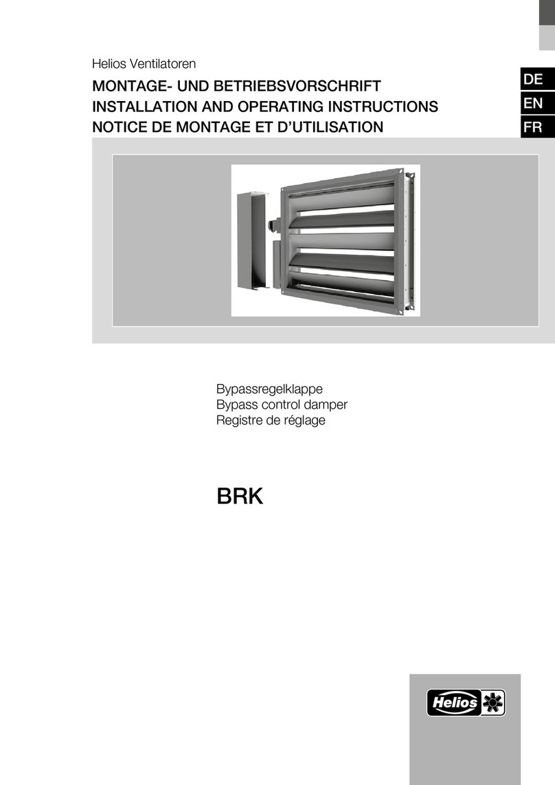
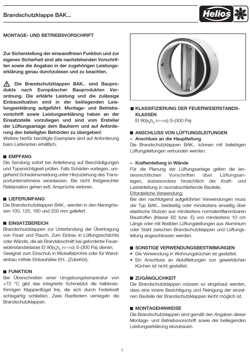
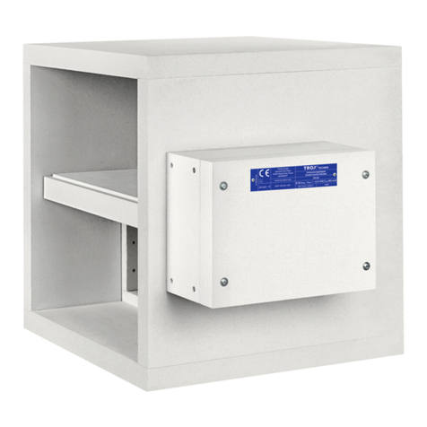
Helios BTK Series User manual

Brandschutz-Tellerventilklappe BTK...
MONTAGE- UND BETRIEBSVORSCHRIFT
91 567-003
Zur Sicherstellung der einwandfreien Funktion und
zur eigenen Sicherheit sind alle nachstehenden
Vorschriften sowie die Angaben in der zugehörigen
Leistungserklärung genau durchzulesen und zu be-
achten.
m Die Brandschutz-Tellerventilklappen BTK.. sind
Bauprodukte nach Europäischer Bauprodukten
Verordnung. Die erklärte Leistung und die zulässige
Einbausituation sind in der beiliegenden Leistungs-
erklärung aufgeführt. Montage- und Betriebsvorschrift
sowie Leistungserklärung haben an der Einsatzstelle
vorzuliegen und sind vom Ersteller der Lüftungsanlage
dem Bauherrn und auf Anforderung den beteiligten
Behörden zu übergeben!
Weitere hierfür benötigte Exemplare sind auf Anforderung
beim Lieferanten erhältlich.
EMPFANG
Die Sendung sofort bei Anlieferung auf Beschädigungen
und Typenrichtigkeit prüfen. Falls Schäden vorliegen,
umgehend Schadensmeldung unter Hinzuziehung des
Transportunternehmens veranlassen. Bei nicht fristge-
rechter Reklamation gehen evtl. Ansprüche verloren.
LIEFERUMFANG
Die Brandschutz-Tellerventilklappen BTK.. werden in den
Nenngrößen 100, 125, 160 und 200 mm geliefert.
EINSATZBEREICH
Brandschutzklappen
zur Unterbindung der Übertragung
von Feuer und Rauch. Zum Einbau in Lüftungsschächte
oder Wände, die als Brandabschnitt bei geforderter Feuer-
widerstandsklasse EI 90(vehoi<–>o) S-(300 Pa) dienen.
Geeignet zum Einschub in Wickelfalzrohre oder für Wand-
einbau mittels Einbauhülse EH.. (Zubehör).
FUNKTION
Bei Überschreiten einer Umgebungstemperatur von
+72 °C gibt das integrierte Schmelzlot die halbkreis-
förmigen Klappenflügel frei, die sich durch Federkraft
schlagartig schließen. Zwei Rastfedern verriegeln die
Brandschutzklappen.
KLASSIFIZIERUNG DER FEUERWIDERSTANDS-
KLASSEN
EI 90(vehoi<–>o) S-(300 Pa)
BTK..
ANSCHLUSS VON LÜFTUNGSLEITUNGEN
– Anschluss an die Hauptleitung
Die Brandschutz-Tellerventilklappen BTK.. können mit be-
liebigen Lüftungsleitungen verbunden werden.
– Krafteinleitung in Wände
Für die Planung der Lüftungsanlage gel-
ten die landesrechtlichen Vorschriften über
Lüftungsanlagen, insbesondere hinsichtlich der Kraft-
und Lasteinleitung in raumabschließende Bauteile.
Erforderliche Verwendung:
Bei den nachfolgend aufgeführten Verwendungen muss der
Typ BTK.. einseitig über elastische Stutzen aus mindestens
normalentflammbaren Baustoen (Klasse B2) von mindes-
tens 10 cm Länge oder mit flexiblen Lüftungslei-tungen
aus Aluminium oder Stahl zwischen Branschutzklappe und
Lüftungsleitung angeschlossen werden.
SONSTIGE VERWENDUNGSBESTIMMUNGEN
• Die Verwendung in Wohnungsküchen ist gestattet.
• Ein Anschluss an Abluftleitungen von gewerblichen
Küchen ist nicht gestattet.
ZUGÄNGLICHKEIT
Die
Brandschutzklappen
müssen so eingebaut werden,
dass eine innere Besichtigung und Reinigung der einzel-
nen Bauteile der
Brandschutzklappen
leicht möglich ist.
MONTAGEHINWEISE
Die
Brandschutzklappen
sind gemäß den Angaben dieser
Montage- und Betriebsvorschrift sowie der beiliegenden
Leistungserklärung einzubauen.
EINBAU
Der Einbau erfolgt direkt ins Wickelfalzrohr (siehe
Abb. 3) oder mittels Einbauhülse EH.. (als Zubehör erhält-
lich) in:
– massive Wände aus Beton, Porenbeton mit der
Feuerwiderstandsklasse F90, und einer Mindesdicke von
100 mm, oder
1

– in massiven Decken aus Beton, Porenbeton mit der
Feuerwiderstandsklasse F90, und einer Mindestdicke
von 150 mm, oder
– in leichten Trennwänden mit der Feuerwiderstands-
klasse F90, und einer Mindestdicke von 100 mm, mit
Metallständerwerk und beidseitiger Beplankung, wenn
die Bedingungen der Leistungserklärung erfüllt sind.
Es ist umlaufend ein Spalt von 20 mm vorzusehen, in
dem die Einbauhülse mit den beiden Mauerankern befes-
tigt wird. Der Spalt ist mit Beton oder Mörtel der Gruppen
II oder III nach DIN 1053 zu verschließen.
VOLUMENEINSTELLUNG
Der Volumenstrom kann durch Drehen des Ventilkegels
gemäß umseitigen Diagrammen angepasst werden.
ZUBEHÖR
WARTUNG UND INSTANDHALTUNG
• Die Produkte sind so einzubauen, dass eine innere
Besichtigung leicht möglich ist.
• Produkt ist vor Erstinbetriebnahme zu reinigen
(Staub trocken entfernen).
• Es sind keine besonderen Wartungsmaßnahmen
notwendig.
• Eine regelmäßige Inspektion und zustandsabhängige
Reinigung ist vorzunehmen (optische Kontrolle auf
Zustand, Verschmutzung, Korrosion).
• Beschädigte Typen sind als Ganzes auszutauschen.
• Wartungsabstände sind entsprechend der jeweils
behördlich vorgeschriebenen Intervalle und abhängig
von der Nutzung der Lüftungsanlage einzuhalten.
• In Deutschland gilt:
Wartung ½ jährlich, sind bei zwei aufeinander folgen-
den Wartungsintervallen keine Auälligkeiten vorhan-
den, kann das Wartungsintervall auf 1 mal jährlich
ausgedehnt werden.
• Die Wartungsvorgänge und getroene Maßnahmen
sind zu dokumentieren, die Ergebnisse sind aufzube-
wahren.
Abb.3
Dn+120
Dn+40
Dn
4. Einbau in Metallständerwände, Einschub in Wickelfalzrohr,Ventil
3.Einbau in Decke, Einschub in Wickelfalzrohr bzw. EH
Gipsverguss
Leichte Trennwand nach DIN 4102-4
oder ABP
EH
BTK
Dn
Dn+50
Wickelfalzrohr
Mörtel
BAK
EH
Dn
Dn+50
Mörtel
Wickelfalzrohr
EH
BAK
mit Einbauhülse
BTK
150 mm
150 mm
4
Einschub in Wickelfalzrohr und Ventil
BAK / BTK
BAK
im Wickelfalzrohr
BTK
im Deckeneinbau
Mb 5404001 / 15.05.2012 / fap
Anlage
Einbau in Decke,
Einschub in Wickelfalzrohr bzw. EH
Dn+120
Dn+40
Dn
4. Einbau in Metallständerwände, Einschub in Wickelfalzrohr,Ventil
3.Einbau in Decke, Einschub in Wickelfalzrohr bzw. EH
Gipsverguss
Leichte Trennwand nach DIN 4102-4
oder ABP
EH
BTK
Dn
Dn+50
Wickelfalzrohr
Mörtel
BAK
EH
Dn
Dn+50
Mörtel
Wickelfalzrohr
EH
BAK
mit Einbauhülse
BTK
150 mm
150 mm
4
Einschub in Wickelfalzrohr und Ventil
BAK / BTK
BAK
im Wickelfalzrohr
BTK
im Deckeneinbau
Mb 5404001 / 15.05.2012 / fap
Anlage
Dn+50
Dn
Mörtel
5. Einbau in Porenbeton, Einbauhülse
Tellerventil
Einbauhülse
5
BAK / BTK
Einbau der Einbauhülse EH
Mb 5405001 / 15.05.2012 / fap
Anlage
Einbau in Metallständerwände
Einschub in Wickelfalzrohr, Ventil
Einbau in Beton oder Porenbeton,
Einbauhülse
Endschalter (Bausatz) BA-S
mit Halter
Best.-Nr. 2585
Endschalter zur BTK Überwach-
ung und Meldung des Betriebs-
zustandes an die zentrale Gebäu-
deleittechnik. Anbaubar an alle
Normdurchmesser (siehe Abb.1).
Brandschutz-Tellerventilklappe BTK...
2

Brandschutz-Tellerventilklappe BTK...
VORBEREITUNG ZUR MONTAGE
Abb. 1 Montage des Endschalters BA-S (Zubehör)
Pos. 1 Halter im Innenring der
Brandschutzklappe
in T-Nut stecken
Pos. 2 Halter zum arretieren in der T-Nut nach unten schieben
Pos. 3/4 BA-S Endschalter auf den Halter aufclipsen. Anschließend die Funktion des Tasters testen.
Abb. 2 Schmelzlot ersetzen
Pos. 1 Geschmolzenes Lot seitlich gegen die Einlegehebel drücken und entnehmen
Pos. 2 Ersatz-Schmelzlot (Zubehör, Artikel-Nr. 84974) in den Schmelzlothalter stecken und einrasten
Abb. 2 Schmelzlot einhängen
Pos. 3 Zum Einhängen des Schmelzlots, die Rastfedern im Innenring der
Brandschutzklappe
nach außen biegen
Pos. 4 Die zwei halbkreisförmigen Klappenflügel soweit zusammendrücken, dass das Schmelzlot in die Rastnase ein-
gehängt werden kann.
Abb.1
Pos. 1 Pos. 2 Pos. 3 Pos. 4
Halter
Abb.2
Pos. 1 Pos. 2 Pos. 3 Pos. 4
Rastfeder
Schmelzlot
Schmelzlothalter
GARANTIEANSPRÜCHE – HAFTUNGSAUS-
SCHLUSS
Wenn die vorgehenden Ausführungen nicht beachtet
werden, entfällt unsere Gewährleistung und Behandlung
auf Kulanz. Gleiches gilt für Haftungsansprüche an den
Hersteller.
VORSCHRIFTEN – RICHTLINIEN
Bei ordnungsgemäßer Installation und bestimmungsge-
mäßem Betrieb entspricht das Gerät den zum Zeitpunkt
seiner Herstellung gültigen Vorschriften und CE-Richt-
linien.
0749 CPR BC1-606-0464-15650.69-2517
3
0749

Brandschutz-Tellerventilklappe BTK...
BTK 125 Tellerdrehungen
Pa
V
·(m3/h)
BTK 160 Tellerdrehungen
Pa
V
·(m3/h)
BTK 200 Tellerdrehungen
Pa
V
·(m3/h)
BTK 100 Tellerdrehungen
Pa
V
·(m3/h)
4


Druckschrift-Nr. 91 567-003/ 22-0015/22-0141/0918/0322
MBV-BTK-2022-03
Service und Information
DHELIOS Ventilatoren GmbH + Co · Lupfenstraße 8 · 78056 VS-Schwenningen F
HELIOS
Ventilateurs · 157. av. Charles Floquet ·
CH HELIOS Ventilatoren AG · Tannstrasse 4 · 8112 Otelfingen
93155 Le Blanc Mesnil Cedex
AHELIOS Ventilatoren · Postfach 854 · Siemensstraße 15 · 6023 Innsbruck GB HELIOS Ventilation Systems Ltd. · 5 Crown Gate · Wyncolls Road
Severalls Industrial Park · Colchester · Essex · CO4 9HZ
Brandschutz-Tellerventilklappe BTK...

Fire dampers BTK...
INSTALLATION AND OPERATING INSTRUCTIONS
91 567-003
In order to ensure complete and eective operation
and for your own safety, all of the following instruc-
tions and the information in the related declaration of
performance should be read carefully and observed.
m The fire dampers BTK.. are construction products
according to the European construction products re-
gulation. The declared performance and permissible
installation conditions are specified in the accompa-
nying declaration of performance. The installation and
operating instructions and declaration of performance
must be available at the deployment site and must be
handed over from the ventilation system developer to
the building owner and the authorities involved upon
request!
Additionally required copies are available from the supplier
upon request.
RECEIPT
The shipment must be checked for damage and correct-
ness immediately upon delivery. If there is any damage,
promptly report the damage by consulting the transport
company. If complaints are not made within the agreed
period, any claims could be lost.
SCOPE OF DELIVERY
The fire dampers BTK.. are delivered in the nominal sizes
100, 125, 160 and 200 mm.
AREA OF APPLICATION
Fire dampers
for preventing the spreading of fire and smo-
ke. For installation in ventilation shafts or walls, which act
as a fire zone with required fire resistance class EI 90(veho
i<–>o) S-(300 Pa).
Suitable for insertion in spiral ducts or for wall installation
using installation sleeves EH.. (Accessories).
FUNCTION
If the ambient temperature of +72 °C is exceeded, the
integrated fusible link releases the semi-circular damper
blades, which snap closed by spring force. Two locking
springs lock the fire dampers.
CLASSIFICATION OF FIRE RESISTANCE CLASSES
EI 90(vehoi<–>o) S-(300 Pa)
CONNECTION OF VENTILATION DUCTS
– Connection to the main line
The fire dampers BTK.. can be connected to any ventila-
tion ducts.
– Force transmission in walls
The state law regulations regarding ventila-
tion systems shall apply for planning the ventila-
tion system, especially regarding the transmission of
force and loads in space-enclosing components.
Required use:
With regard to the following uses, model BTK.. must be
connected on one side using flexible connectors made of
at least normally flammable material (class B2) of at least
10 cm in length or flexible ventilation ducts made of alu-
minium or steel between shut-o devices and ventilation
ducting.
OTHER TERMS OF USE
• Use in domestic kitchens is permitted.
• The connection to extract air ducts of commercial
kitchens is not permitted.
ACCESSIBILITY
The fire dampers must be installed so that the internal in-
spection and cleaning of the individual components of the
fire protection valves
is as easy as possible.
INSTALLATION INSTRUCTIONS
The fire dampers must be installed in accordance with
these installation and operating instructions as well as the
accompanying declaration of performance.
INSTALLATION
The fire dampers are installed directly in spiral ducting (see
Fig. 3) or using installation sleeves EH.. (available as ac-
cessories) in:
– solid concrete walls, aerated concrete with fire resistan-
ce class F90, and a minimum thickness of 100 mm, or
BTK..
1

– in solid concrete walls, aerated concrete with fire resis-
tance class F90, and a minimum thickness of 150 mm,
or
– in lightweight partition walls with fire resistance class
F90, and a minimum thickness of 100 mm, with metal
studs and panelling on both sides, provided the conditi-
ons of the declaration of performance are fulfilled.
There must be a circumferential gap of 20 mm, in which
the installation sleeve is attached with the two wall an-
chors. The gap must be sealed with concrete or mortar
from groups II or III according to DIN 1053.
VOLUME SETTING
The flow rate can be adjusted by rotating the valve plug
according to the diagrams overleaf.
ACCESSORIES
SERVICING AND MAINTENANCE
• The products must be installed so that internal inspec-
tion is as easy as possible.
• The product must be cleaned prior to initial commis-
sioning (remove dust-dry).
• There are no special maintenance requirements.
• The product must be regularly inspected and cleaned
depending on condition (visual inspection of condition,
contamination, corrosion.
• Damaged models must be exchanged as a whole.
• Maintenance intervals must be observed according to
the respective ocially prescribed intervals and de-
pending on the usage of the ventilation system.
• The following applies in Germany:
Maintenance semi-annually, if there are no abnormal-
ities in two consecutive maintenance intervals, the
maintenance interval can be extended to 1 x annually.
• The maintenance operations and measures taken
must be documented and the results must be stored.
Fig.3
Dn+120
Dn+40
Dn
4. Einbau in Metallständerwände, Einschub in Wickelfalzrohr,Ventil
3.Einbau in Decke, Einschub in Wickelfalzrohr bzw. EH
Gipsverguss
Leichte Trennwand nach DIN 4102-4
oder ABP
EH
BTK
Dn
Dn+50
Wickelfalzrohr
Mörtel
BAK
EH
Dn
Dn+50
Mörtel
Wickelfalzrohr
EH
BAK
mit Einbauhülse
BTK
150 mm
150 mm
4
Einschub in Wickelfalzrohr und Ventil
BAK / BTK
BAK
im Wickelfalzrohr
BTK
im Deckeneinbau
Mb 5404001 / 15.05.2012 / fap
Anlage
Installation in ceiling,
Insertion in spiral duct or installation sleeve EH
Dn+120
Dn+40
Dn
4. Einbau in Metallständerwände, Einschub in Wickelfalzrohr,Ventil
3.Einbau in Decke, Einschub in Wickelfalzrohr bzw. EH
Gipsverguss
Leichte Trennwand nach DIN 4102-4
oder ABP
EH
BTK
Dn
Dn+50
Wickelfalzrohr
Mörtel
BAK
EH
Dn
Dn+50
Mörtel
Wickelfalzrohr
EH
BAK
mit Einbauhülse
BTK
150 mm
150 mm
4
Einschub in Wickelfalzrohr und Ventil
BAK / BTK
BAK
im Wickelfalzrohr
BTK
im Deckeneinbau
Mb 5404001 / 15.05.2012 / fap
Anlage
Dn+50
Dn
Mörtel
5. Einbau in Porenbeton, Einbauhülse
Tellerventil
Einbauhülse
5
BAK / BTK
Einbau der Einbauhülse EH
Mb 5405001 / 15.05.2012 / fap
Anlage
Installation in metal stud walls
Insertion in spiral duct, valve
Installation in concrete or aerated concrete,
installation sleeve
Spiral duct
Mortar
BTK in ceiling installation
Gypsum grouting
Lightweight partition wall accor-
ding to DIN 4102-4 or ABP
Poppet valve Installation sleeve
Mortar
Limit switch (kit) BA-S
with holder
Ref. no. 2585
Limit switch for BTK monitoring
and signalling the operating sta-
tus to the central building control
system. Attachable to all standard
diameters (see Fig.1).
Fire dampers BTK...
2

Fire dampers BTK...
ASSEMBLY PREPARATION
Fig. 1 Assembly of end switch BA-S (Accessories)
Pos. 1 Insert holder in the inner ring of the
fire damper
into T-nut
Pos. 2 Push holder down to lock in the T-nut
Pos. 3/4 Clip BA-S end switch to the holder. Then test the functioning of the switch.
Fig. 2 Replace the fusible link
Pos. 1 Push molten solder to the side against the lever and remove
Pos. 2 Insert replacement fusible link (Accessories, Ref. no. 84974) in the fusible link holder and snap into place
Fig. 2 Attach the fusible link
Pos. 3 In order to attach the fusible link, bend the locking springs in the inner ring of the
fire damper
outwards
Pos. 4 Push the two semi-circular damper blades together so that the fusible link can be attached to the locking catch.
Fig.1
Pos. 1 Pos. 2 Pos. 3 Pos. 4
Holder
Fig.2
Pos. 1 Pos. 2 Pos. 3 Pos. 4
Catch spring
Fusible link
Fusible link holder
WARRANTY CLAIMS – EXCLUSION OF LIABILITY
If the previous instructions are not observed, our warran-
ty and treatment on a goodwill basis shall not apply. The
same applies for liability claims against the manufacturer.
REGULATIONS – GUIDELINES
If the product is installed correctly and used to its inten-
ded purpose, it conforms to all applicable regulations and
CE guidelines at its date of manufacture.
0749 CPR BC1-606-0464-15650.69-2517
3
0749

Fire dampers BTK...
BTK 125 Poppet rotations
Pa
V
·(m3/h)
BTK 160 Poppet rotations
Pa
V
·(m3/h)
BTK 200 Poppet rotations
Pa
V
·(m3/h)
BTK 100 Poppet rotations
Pa
V
·(m3/h)
4


Print no. 91 567-003/ 22-0015/22-0141/0918/0322
MBV-BTK-2022-03
Service and Information
DHELIOS Ventilatoren GmbH + Co · Lupfenstraße 8 · 78056 VS-Schwenningen F
HELIOS
Ventilateurs · 157. av. Charles Floquet ·
CH HELIOS Ventilatoren AG · Tannstrasse 4 · 8112 Otelfingen
93155 Le Blanc Mesnil Cedex
AHELIOS Ventilatoren · Postfach 854 · Siemensstraße 15 · 6023 Innsbruck GB HELIOS Ventilation Systems Ltd. · 5 Crown Gate · Wyncolls Road
Severalls Industrial Park · Colchester · Essex · CO4 9HZ
Fire dampers BTK...
This manual suits for next models
4
Table of contents
Languages:
Other Helios Fire And Smoke Damper manuals
Popular Fire And Smoke Damper manuals by other brands

Nailor
Nailor 1210SS manual

Jøtul
Jøtul 340955 Installation and operating instructions

actionair
actionair Smoke/Shield PTC Installation and operating instructions
Emerson
Emerson Enardo EN FVFA Series instruction manual

NCA
NCA FSD-RD-211 Installation, operation & maintenance instructions

System air
System air FDS-3G EX Series manual
System air
System air PK-I-R-EI60S manual
System air
System air IMOS-RK Technical conditions

eControls
eControls Comfort365 C365T11 Installation
VPro
VPro MA Series instruction manual

FläktGroup
FläktGroup ETCE Instructions for installation, operation and maintenance

Mandik
Mandik SEDS-L Technical specifications
