3
DC Inverter Multi VRF System II
Service Manual
PRODUCT
Due to the latest communication method—CAN Bus Communication, system’s anti-interference capability is stronger and the control
on indoor units is more accurate, with higher reliability. Specialized shield wire is no more needed and ordinary communication wire can be
applied in the construction, which has increased the installation exibility.
(3) Long connection pipe
The maximum length of connection pipe is 300m (in total) and the farthest connection pipe between indoor and outdoor units can be
120m’s long, which has extended the installation condition and reduced the limit of installation distance.
(4) Wide operation range
Units can operate reliably in a wide temperature range (cooling: -5~48oC, heating: -20~27oC).
(5) Fine sound quality
Through a series of optimized measures, system has reduced the throttle noise and oil return noise of indoor units, gas bypass noise,
etc. so that units are more comfortable regarding sound quality.
(6) Intelligent PID capacity regulation
With the independently developed PID capacity regulation technology, units are able to control the indoor ambient temperature more
quickly and reduce the uctuation of room temperature.
(7) Complete protection
Units are equipped with a series of protection to accurately identify errors and protect the units, which has ensured reliable and safe
operation.
4 SPECIFICATIONS
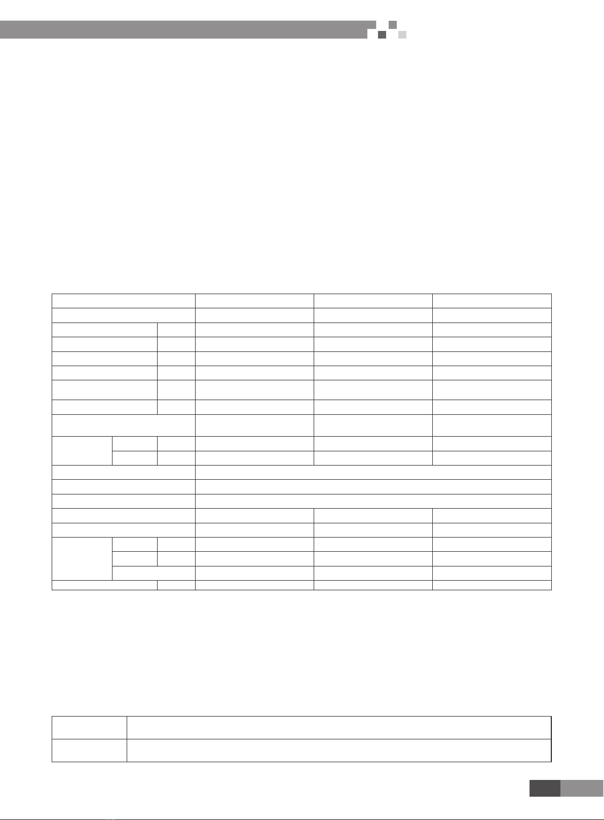
4.1 Specications
Model GMV-120WL/A-T GMV-140WL/A-T GMV-160WL/A-T
Product code CN850W0180 CN850W0170 CN850W0160
Cooling capacity kW 12.1 14 16
Heating capacity kW 14 16.5 18.5
Circulating air volume m3/h 6000 6300 6600
Noise dB(A) 55 56 58
Refrigerant charge
volume kg 5 5 5
Energy efciency level Level 1 1 1
Power supply 220-240V~50Hz
208-230V~60Hz
220-240V~50Hz
208-230V~60Hz
220-240V~50Hz
208-230V~60Hz
Rated power
input
Cooling kW 3.05 3.98 4.85
Heating kW 3.27 3.99 4.67
Unit Dimensions (mm)(WxDxH) 900×340×1345
Package Dimensions (mm)(WxDxH) 998×458×1515
Compressor QXAS-F428zX050A
Water-proof level IPX4 IPX4 IPX4
Suitable climite T1 T1 T1
Connection
pipe
Gas mm Ф15.9 Ф15.9 Ф19.05
Liquid mm Ф9.52 Ф9.52 Ф9.52
Connection Method Bell mouth connection Bell mouth connection Bell mouth connection
Net weight kg 110 110 110
Note:
① . Units conform to design standard: GB/T 18837-2002.
② . Specications may be changed due to product improvement. Please refer to nameplates of the units.
③ . Noise data are collected from a semi-anechoic room. Decibels may be slightly higher in actual operation due to environmental
change.
④ . Refrigerant charge volume listed in the table is based on the condition where indoor and outdoor units are at a same level and with
no connection pipe. Supplementary refrigerant needs to be charged according to actual circumstance.
⑤ . The sectional area of conducting wire is only applicable when the length is within 15m. If it’s over 15m’s long, sectional area must
be increased accordingly, otherwise, over-current may burn the wires.
4.2 Operation range
Cooling Outdoor temperature: -5~48oC
Heating Outdoor temperature: -20~27oC