Helios SD Series User manual

SD SERIES RECTIFIER / DC POWER SUPPLY USERS MANUAL
24V - 48V - 110V - 220V DC
10A - 10000A
September 2020
SD Series Rectifier / DC PowerSupply
Users Manual
Ver1.5
PAGE :
1
ENGLISH
Because of the high leakage current, this equipment should be operated only after
it is earthed.
HIGH LEAKAGE CURRENT
This equipment if compatable to EMC directive 89/336/EEC and to conditions in
released technical specifications. The compability remains only if related
directions are followed and only if the equipment is used with accessories
approved by the manufacturer.
ELECTROMAGNETIC COMPABILITY
In custom designs, there can be minor differences between this manual and the
equipment.
IMPORTANT
This users manual contains setup, operation and maintenance information for SD
Series Rectifiers / Power Supplies.
Before starting setup and operation of the equipment, complete users manual
should be read carefully.
Before operation, the rectifier should be prepared by an authorized technical
personnel approved by DEALER. The warranty will be void, if this direction is
not followed.
Please contact DEALER customer service, if you see any problem about any
process described in this users manual.
The manufacturer reserves the right to change the design of the equipment without
notice.
IMPORTANT

SD Series Rectifier / DC PowerSupply
Users Manual
Ver1.5
PAGE :
2
ENGLISH
CAUTION
1. There are no user servicable parts inside.
2. Even after the equipment is disconnected from batteries and input connections,
a intervention to the interior of the equipment contains risk of electric shock.
3. Ventilation holes should be kept open and no objects should be inserted.
4. In the environment where the equipment will be operated, the temperature and
humidity should be relevant.
5. Batteries should be kept away from high temperature, otherwise they can
explode.
6. The equipment can not be operated in an environment having flammable and
explosive devices.
7. Setup, maintenance and repair of the equipment should be performed only by
trained, experienced and authorised technical personnel.
8. When working on live equipment a second person who is aware of all safety
precautions and emergency actions should be present at all times.
9. It is the responsibility of each individual to be aware of national legislation,
local legislation and site rules governing safety and working practices.
10. Use only good quality insulated tools and accessories, properly maintained
and calibrated instruments, and suitable and adequate supports and lifting
equipment.
11. Electrical energy can be supplied from the AC supply, external batteries or the
external alarm or auxiliary control terminals.

SD Series Rectifier / DC PowerSupply
Users Manual
Ver1.5
PAGE :
3
ENGLISH
CONTENT
1. GENERAL INTRODUCTION 4
1.1 SYSTEM DESCRIPTION 4
1.2 OPERATION THEORY 5
1.3 TRANSITION BETWEEN CHARGE MODES 7
1.4 CURRENT LIMITING 9
1.5 GENERAL FEATURES 10
1.6 PHYSICAL FEATURES 11
1.7 ELECTRICAL FEATURES 12
2. SETUP 13
2.1 OPENING PACKAGE 13
2.2 CHOOSING PROPER PLACE 13
2.3 ELECTRICAL CONNECTION 13
3. OPERATION 14
3.1 TURNING ON THE EQUIPMENT 14
3.2 TURNING OFF THE EQUIPMENT 14
3.3 AUTOMATIC STARTUP 15
4. SERVICE AND MAINTENANCE 16
4.1 PERIODICAL MAINTENANCE 16
4.2 FAILURES 16
4.3 BEFORE CALLING SERVICE 16
5. FRONT PANEL 18
5.1 CHARACTER LCD PANEL 19
5.2 GRAPHIC TOUCH DISPLAY PANEL 32
6. OPTIONS 40
6.1 ALARM & COMMUNICATION INTERFACE BOARD (OPS-01) 42
6.2 DC EARTH LEAKAGE MONITORING (OPS-02) 45
6.3 DC SUPPLY & BATTERY MONITORING (OPS-03) 46
6.4 GAUGES (OPS-04) 46
6.5 LOAD VOLTAGE LIMITATION MODULE / VOLTAGE DROP (OPS-05) 47
6.6 BATTERY CHARGE TEMPERATURE COMPENSATION (OPS-06) 47
6.7 INTERNAL CABINET LIGHTING (OPS-07) 47
6.8 INTERNAL CABINET HEATER (OPS-08) 47
6.9 INPUT POWER MEASUREMENT (OPS-09) 47
6.10 RELAY BOARDS (OPS-10) 48
6.11 TRANSDUCERS (OPS-11) 48
6.12 12 PULSE OPERATION (OPS-12) 49
6.13 ACTIVE PARALLEL CURRENT SHARING (OPS-13) 50
6.14 FAST ACTING SEMICONDUCTOR FUSES (OPS-14) 53
6.15 FAN FAILURE MONITORING (OPS-15) 53
7. CABLE TYPES AND CROSS SECTIONS 54
8. SYMBOL LIST 55

SD Series Rectifier / DC PowerSupply
Users Manual
Ver1.5
PAGE :
4
ENGLISH
1. GENERAL INTRODUCTION
1.1 SYSTEM DESCRIPTION
SD Series Rectifier / DC Power Supply is a high technology equipment, including all protection and
control systems, which is designed and manufactured to convert 1 phase or 3 phase AC voltage to
pure and regulated DC voltage. It provides DC power, which is especially important for industrial,
telecom and military applications.
When this system is used with a battery group at its output, this equipment charges battteries and
acts as a uninterrupted DC power source.
This equipment contains an input isolation transformer and provides full electrical isolation between
input supply and DC output.
This uses all advantages of DSP (Digital Signal Processor) control. It provides advanced user
interface, smart diagnostics and advanced communication features.
When used as battery charger, it can perform battery charge in 3 different modes:
•Float charge
•Equalizing charge
•Boost charge

SD Series Rectifier / DC PowerSupply
Users Manual
Ver1.5
PAGE :
5
ENGLISH
Measurement &
Feedback
Measurement &
Feedback
Rectifier
Input
(AC)
Thyristor
Rectifier
Bridge
Filtering
Components
Rectifier
Battery
Output
Voltage
Dropper
(option)
Rectifier
Load Output
(option)
Input
Isolation
Transformer
Comm.
Interface
(option)
DSP
Control
LCD Panel
Keypad
1.2 OPERATION THEORY
Rectifier block diagram is shown below.
Figure 1.1 SD Series Rectifier Block Diagram
Figure 1.2 SD Series Rectifier Single Line Diagram (includes optional features)
SD Series Rectifier / DC PowerSupply
Users Manual
Ver1.5
PAGE :
6
ENGLISH
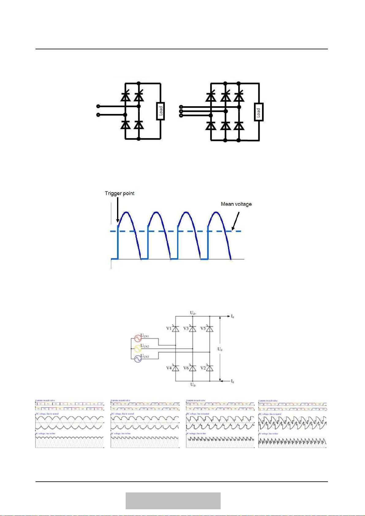
Thyristors are used as semiconductor switch. Single phase full controller thyristor bridge topology
is call B2C. Three phase full controlled thyristor bridge is called B6C.
Single phase (B2C) topology Three phase (B6C) topology
Operation of the system is based on phase control. The DSP controller trigs the thyristors connected
to the secondary of AC transformer, so adjusting the mean DC bus voltage.
Generation of DC voltage by adjusting the trigger points is shown below.
Figure 1.3 Phase control in single phase system
Generation of DC voltage in three phase system for different phase control trigger points are shown
below.
Figure 1.4 Phase control in three phase system

SD Series Rectifier / DC PowerSupply
Users Manual
Ver1.5
PAGE :
7
ENGLISH
1.3 TRANSITION BETWEEN CHARGE MODES
The device can apply 3 different charging voltages. These are Float, Equalize and Boost Charge
charge voltages. When in auto charge mode, the device automatically switches between Float and
Equalize charge modes.
Float Charge Mode
In this charging mode, the device applies Float charging voltage to the load (battery), limiting the
current if necessary. There is no time limit. The float charge charges the battery at buffering value.
Equalize Charge Mode
In this charging mode, the device applies the Equalize charging voltage to the load (battery),
making current limit if necessary. There is no time limit. The Equalize charge is a fast charge which
is high in the battery charging process.
Boost Charge Mode
In this charging mode, the device applies Boost charging voltage to the load (battery), limiting the
current if necessary. This charging mode is also limited in terms of time with the Boost Duration
setting value. If this time expires, the device returns to Float Charge and Fast Charge is blocked for
the next 1 hour. After 1 hour, the device switches itself to Boost Charge again.
The quick charge is used only for the first commissioning for some special types of batteries.
Automatic Charge Mode
In a rectifier set to operate in automatic charging mode, automatic switching between float and
balancing charges is done automatically. These criterias are current value and time. As a current
criterion, two threshold values are mentioned: Flotation Current and Equalize Current. As a time
criterion, there is only one value called Boost Duration. All three values can be set by the user under
the Settings menu. The mechanism works as follows:
1. If the current value drawn from the battery is below the Float currrent set value, the device
switches to Float Charge mode within 30 seconds.
2. If the current value drawn from the battery is above the set value of the Equalizing Current, the
device switches to Equalizing Charge mode within 30 seconds. However, this can be done if at
least 60 minutes have passed since the last successful Fast Charge
3. If the device has entered Equalize Charge mode for any reason, Equalizing Charge can last as
long as the Boost Duration value, after which the device will go into Float Charge mode if the
device is still in Equalizing Charge mode and start the 60 minute Fast charge Block period
mentioned in the second item. As long as fast charge block is active, the device can not switch
to Equalize charge.

SD Series Rectifier / DC PowerSupply
Users Manual
Ver1.5
PAGE :
8
ENGLISH
Figure 1.5 SD Series Automatic Charge Mode Transition Flowchart
N
Current < Ifloat ?
Y
N
Current > Iequalize ?
Y
N
Fast Charge
Blocked ?
Y
N
Charge Mode is
Equalize ?
Y
N
Fast Charge time
finished ?
Y
N
Fast Charge Block
time expired ?
(1 hour)
Y
Fast Charge Block
finished
Block Fast charge
for the next
1 hours
Charge Mode = FLOAT
Charge Mode = EQUALIZE
Charge Mode = FLOAT
SD Series Rectifier / DC PowerSupply
Users Manual
Ver1.5
PAGE :
9
ENGLISH
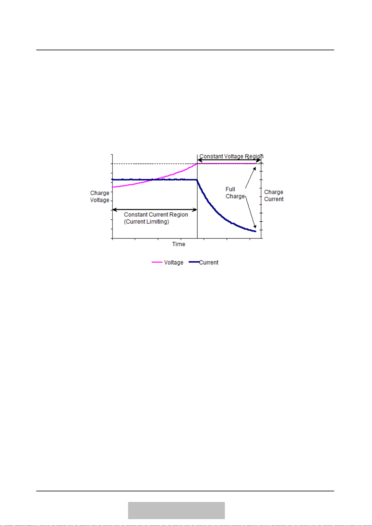
1.4 CURRENT LIMITING
Current limiting is the action that the rectifier reduces its voltage to limit the current. The SD series
rectifier has the feature. If the output current exceeds the Current Limit setpoint or battery current
exceeds Batt. Current Limit setpoint (both hare defined under Main Menu > Setup), the output
voltage is reduced until the current drops below the setpoint. In this case, a Current Limit message
is displayed. This is constant curent operation mode. The rectifier do not trip its outputs.
During the battery charge process, an empty battery may force the rectifier to run at current limit
mode for a short period. After the battery is enough charged, it will demand for less current and the
rectifier will leave the current limit.
Figure 1.6 Battery Charging with Current Limiting

SD Series Rectifier / DC PowerSupply
Users Manual
Ver1.5
PAGE :
10
ENGLISH
1.5 GENERAL FEATURES
Advantages and properties of SD Series Rectifiers are as following :
•1 phase or 3 phase input (model dependent)
•Internal isolation transformer at input
•Full controlled conventional rectifier
•Smart control and high reliability with DSP (Digital Signal Processor)
•Float charge, equalizing charge and boost charge modes
•Automatic and manual charge modes
•Low output voltage ripple and high reliability
•2x16 character LCD display, showing measurements, status and alarm messages
•Soft start
•Led displays for easy observation of Rectifier status. Audible alarm.
•Programmable current limitation
•Operation as voltage source or currentsource
•Calibration of measurements from frontpanel
•Language selection from front panel (English / German / Turkish / Netherland /Portuguse)
•DC Low / High, Line Failure, Over Temperature, Short Circuit protections
•Ability to program all operation parameters (password protected)
•Log records with date and time stamp up the 200 events.
•Programable alarm relay contact outputs (Up to 16 relays) *Option
•Possibility of monitor and control over RS232-RS485. Modbus communication.*Option
•Earth leakage monitoring *Option
•Battery temperature compensation *Option
•Ability to monitor batteries and battery low alarm, even when the AC input fails (option)
•Active parallel (current sharing) operation up to 4 devices *Option
•Easy observation via analog gauges (input / output / battery voltages / currents) *Option
•Battery test with adjustable voltage and duration *Option
•Transducers for input / output voltage(s) / current(s) (4-20mA and 0-10V) *Option
•12 pulse option to limit input current distortion. *Option
•Internal cabinet light. *Option
•Internal cabinet anticondensation heater. *Option

SD Series Rectifier / DC PowerSupply
Users Manual
Ver1.5
PAGE :
11
ENGLISH
1.6 PHYSICAL FEATURES
INDICATIONS AND ALARMS
Digital Measurements (On LCD Display) *1
DC Output Voltage / Current
AC Input Voltage(s) /Current(s)
Battery Voltage / Current
Battery Ambient Temperature
Charge Mode
Date & Time
AC Input Frequency
AC Input Power(s) / Power Factor(s)
Alarms
Alarm Messages (On LCD Display) *1
Line Failure / Line Low
DC Low / High
Current Limit
Battery Too Low / Low / High
Over Temperature / Temperature Pre Alarm
Earth Fault
Memory Error
Fan Failure
Breaker Open
Fuse Failure
Door Open
Hardware Block
Probe Failure
Emergency Stop
Parallel Fault
12 Pulse Failure
Battery Test Failed
Led Indicaters
Input AC OK / Fail
Operation
Common Alarm
COMMNICATION & REMOTE MONITORING
Serial Communication *Option
RS232 / RS485 Isolated Serial Port (Modbus Communication)
Dry Contact Outputs *Option
4 programable alarm contact output
ENVIROMENTAL FEATURES
Operation Temperature
-5°C / + 50°C *2
Storage Temperature
-20°C / + 50°C
Cooling
Air Natura lor Fan Forced, model dependent
Relative Humidity
0% –90% (non condensing)
Operation Altitude
2000 meters maximum
*1 Some of the displayed measurements and alarm are optional.
*2 Custom solutions for very low ambient temperatures is possible, by adding termostat controlled heaters. Consult
your dealer.
SD Series Rectifier / DC PowerSupply
Users Manual
Ver1.5
PAGE :
12
ENGLISH
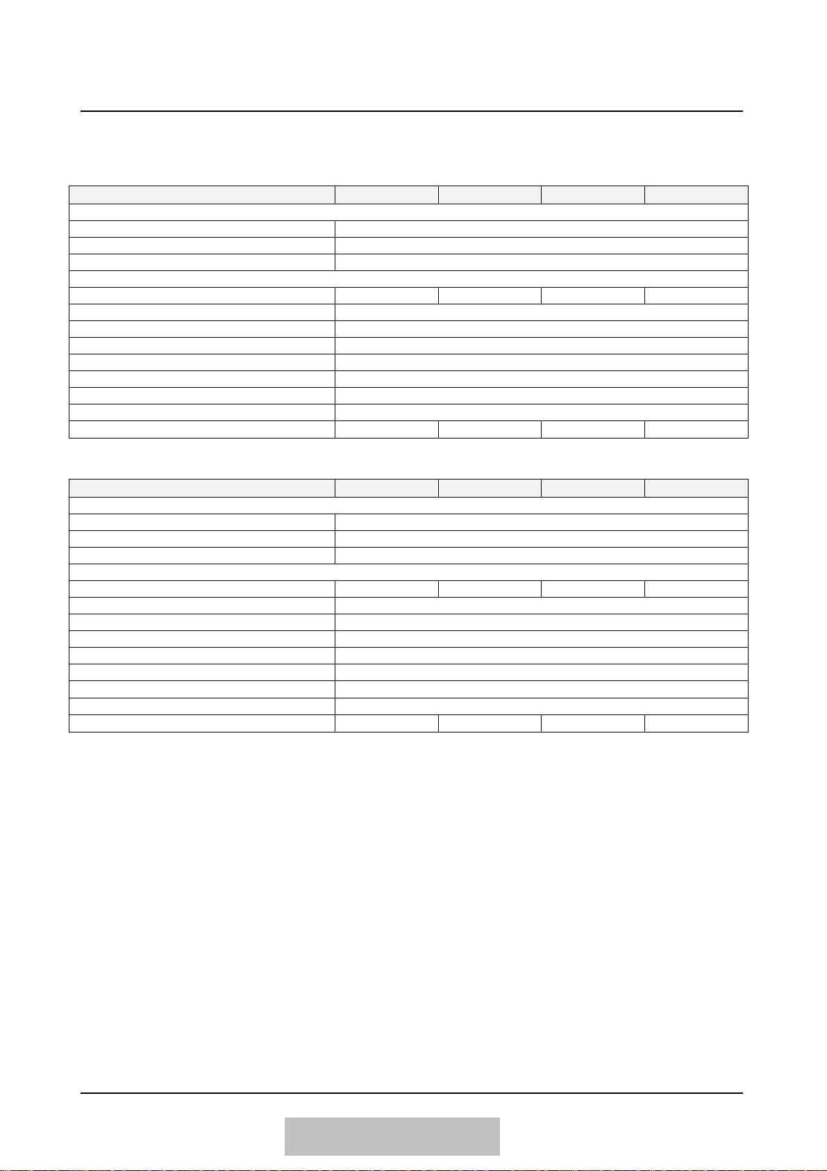
1.7 ELECTRICAL FEATURES
1.7.1 ELECTRICAL FEATURES (1 phase inputdevices)
24V
48V
110V
220V
INPUT
Voltage (AC)
110V / 120V / 220V / 230V / 240V
Frequency
47 Hz –63 Hz, with automatic adaptation
Power Factor (nominal)
0.75
OUTPUT
Voltage (DC)
24V ± 1%
48V ± 1%
110V ± 1%
220V ± 1%
Current (Nominal)
10A … 100A
Float Charge Adjustment Range
80% - %115% x nominal
Equalizing Charge Adjustment Range
80% - %125% x nominal
Boost Charge Adjustment Range
80% - %125% x nominal
Current Limit Adjustment Range
25% - %100% x nominal
Ripple
< 1.5 %
Regulation
< 1.0 %
Efficiency
76-82%
78-83%
80-85%
82-85%
1.7.2 ELECTRICAL FEATURES (3 phase inputdevices)
24V
48V
110V
220V
INPUT
Voltage (AC)
200V / 380V / 400V / 415V / 440V, with or without neutral
Frequency
47 Hz –63 Hz, with automatic adaptation
Power Factor (nominal)
0.80
OUTPUT
Voltage (DC)
24V ± 1%
48V ± 1%
110V ± 1%
220V ± 1%
Current (Nominal)
10A … 10000A
Float Charge Adjustment Range
80% - 115% x nominal
Equalizing Charge Adjustment Range
80% - 125% x nominal
Boost Charge Adjustment Range
80% - 125% x nominal
Current Limit Adjustment Range
25% - 100% x nominal
Ripple
< 1.5 %
Regulation
< 1.0 %
Efficiency
80-87%
85-89%
86-92%
87-93%
SD Series Rectifier / DC PowerSupply
Users Manual
Ver1.5
PAGE :
13
ENGLISH
Connect and control ground (PE) connection. Definitly, the equipment should’nt be operated
without ground connection.
CAUTION
For 6 pulse, 3 phase input devices, input supply phase sequence and direction may be ignored.
For 12 pulse, 3 phase input devices, input supply phase sequence is important. The input phase
sequence may be seen inside the About menu, Input Voltage item. After connecting supply, be sure
that the phase rotation direction sign is ‘-‘ (minus)
NOTE
2. SETUP
2.1 OPENING PACKAGE
When the equipment is delivered to you, first to be examined is a possible damage during transport.
Therefore, examine the equipment carefully. For a possible future use, save the packet and wooden
pad of the rectifier after unpacking.
2.2 CHOOSING PROPER PLACE
1. For a proper ventilation, minimum distance between the rear of the rectifier and any nearby
object should me minimum 20 cm.
2. Choose a place with proper temperature and humidity.
3. Do not choose any place which can cause dust and corrosion.
4. The place chosen should not have direct sunshine and shouldnt be near any heatingsource.
5. Operating the equipment in proper conditions will increase it lifetime.
2.3 ELECTRICAL CONNECTION
All electrical connections of the rectifier exist on the back of the front door of the enclosure. All
required connections to connection panel of rectifier should be made by DEALER service personnel
or by the approval of DEALER service personnel.
Before making the connections all power switches, isolators and circuit breakers must be in OFF
position.
Input AC supply should be connected to X1 terminal.
In devices where battery output and load output are seperated, battery should be connected to X2
and load should ve connected to X3.
In devices where battery output and load output are common, both battery and load should be
connected to X2 and load should ve connected to X3.
Ground must be connected.
Your device may have different connections and terminals, depending on your project and
specifications. Please refer to the drawings and terminal labels before proceed.
CAUTION
SD Series Rectifier / DC PowerSupply
Users Manual
Ver1.5
PAGE :
14
ENGLISH
3. OPERATION
3.1 TURNING ON THE EQUIPMENT
1. Apply 1 or 3 phase line voltage from the connected distribution panel to the rectifier, when the
rectifier input breaker K1 is in OFF position.
2. Switch the input breaker K1 to ON position. Rectifier will be energized and welcome message
will be shown on the front panel.
3. With a soft start , the rectifier will start to generate DC output voltage, if automatic startup is
set. (See Section 5, Front Panel)
4. If manual startup is set, the rectifier will wait without generating DC. In this case, push ON
buttons on the front panel.
5. From the rectifier side of the K2 output breaker, control the DC voltage, with a voltmeter, or
from the LCD panel.
6. Switch the K2 output breaker to ON position. Rectifier will feed output loads. If exists, switch
the K3 output breaker to ON position, too.
7. Output voltage and output current can be observed via the LCD panel.
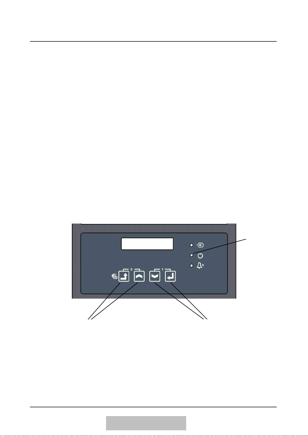
3.2 TURNING OFF THE EQUIPMENT
1. Push OFF buttons on the front panel of the rectifier. Rectifier will stop generate DC voltage.
2. Switch input breaker K1 and output / load breakers K2 / K3 to OFF position.
Operation
Status
Led
For STOP (Stopping DC generation)
pres these 2 buttons together
For START (Starting DC generation)
press these 2 buttons together
Figure 3.1 Starting and Stopping Rectifier, Character Panel

SD Series Rectifier / DC PowerSupply
Users Manual
Ver1.5
PAGE :
15
ENGLISH
Figure 3.2 Starting and Stopping Rectifier, Graphic Panel
3.3 AUTOMATIC STARTUP
It can be programmed, whether the rectifier starts its operation itself or not, when the AC input
supply is applied. (See Section 5, Front Panel)
A rectifier programmed for automatic startup will automaticly start it operation and generate DC,
when the AC input supply is applied. This option is especially preferred for far installations, where
user intervention is not possible. In this mode, if a trip because of an alarm condition occurs, the
rectifier will atutomaticly restart and generate DC, after the alarm condition is disappered. This
status can be observed by the blinking operation led.
A rectifier programmed for manual startup will wait for the user to push ON buttons to start, after
the AC input supply is applied.
A device programmed for Automatic Startup resets the DC High alarm, 20 seconds after it has been
detected. If the alarm appears again after the restart, this scenario is repeated 4 times. After the 4th
attempt, if the time lapse between last two alarm was less than 10 minutes, the rectifier decides that
there is a permanent problem and service needed, therefore is stops automatic alarm reset and
automatic restart and remain in alarm state.
Run (Generating DC) / Stop
Button
Operation Status
Information

SD Series Rectifier / DC PowerSupply
Users Manual
Ver1.5
PAGE :
16
ENGLISH
There are no by the user servicable parts inside the equipment, therefore DO NOT OPEN THE
COVER OF THE EQUIPMENT. Because of possible external battery connection and dry contact
relay outputs, THERE MAY BE HIGH VOLTAGE INSIDE THE EQUIPMENT, EVEN WHEN
THE RECTIFIER IS TURNED OFF. Do not permit unauthorized persons to intervent any failure,
otherwise, the warranty will be void and moreover, significant injury may occour.
CAUTION
4. SERVICE AND MAINTENANCE
Under normal operating conditions only preventative maintenance is required. The intervals
between maintenance actions will vary according to the level of remote monitoring and the standard
of cleanliness of the equipment room.
4.1 PERIODICAL MAINTENANCE
The rectifier equipment is designed for a very minor maintenance requirement. Only fulfil
conditions described below.
1. Clear the dust piled up in ventilation holes of the equipment.
2. You may clean the cover of the equipment with a moist cloth.
3. Record all abnormal occurrences in the service log
4. Visually check electrical connections and component for signs of overheating or corrosion.
Rectify as necessary.
4.2 FAILURES
As mentioned before, only authorized personnel may perform maintenance of the equipment. In any
abnormal situation, before calling service, check the points described below.
4.3 BEFORE CALLING SERVICE
The most simple failure definition for a car problem is “Car is defective.” But, this will not help to
the one who must fix the problem, especially when he is not beside the car. There can be several
reasons :
-No fuel
-Blown gear
-Bad battery
-No start key
-No engine
- …
Therefore, the information provided to the service personel is very important. The information will
help him to better undestand the situation.
Please, before calling the service, save your devices model and serial number and be ready to
answer the following questions :
1. Did you read the users manual ?
2. Is this the first start up of the device or it was working properly before ?

SD Series Rectifier / DC PowerSupply
Users Manual
Ver1.5
PAGE :
17
ENGLISH
3. Is there energy on the panel, which the device is connected ?
4. Which alarms are displayed on the LCD display ?
5. Cihaz ön panelde LCD göstergede ne alarmlar veriyor ?
6. What are are status of the LED indicaters ?
7. Did you apply START command ? Is the OPERATION led (middle of 3) on ?
8. Are the boards and front panel energized when you switch the AC input breaker on?
9. What are the status of breakers ?
10. Is this a problem apeearing rearly or is it permanently existing ?
11. What are the load and battery ?
12. Did you experience any anormality in you utiliy in last times ?

SD Series Rectifier / DC PowerSupply
Users Manual
Ver1.5
PAGE :
18
ENGLISH
5. FRONT PANEL
Depending on the model of the device, Display Panel can be in one of the following forms:
-2x16 character LCD Display, Keypad, Led Indicators
-Graphic Touch Display Panel

SD Series Rectifier / DC PowerSupply
Users Manual
Ver1.5
PAGE :
19
ENGLISH
5.1 CHARACTER LCD PANEL
5.1.1 STRUCTURE OF FRONT PANEL
The front panel of the Rectifier contains a 2x16 character LCD (Liquid Crystal Display), control
buttons and leds. Via LCD, measurements and status / alarm messages are displayed in a format,
which can be easyly understood. Parts in front panel and their functions are given below.
Figure 5.1 Rectifier Front Panel
1
LCD Display
Measured values, status and alarm messages of the equipment are displayed in this 2x16
character LCD display.
2
Esc Button
This buton is used to get back from a submenu or to escape from adjustment without
validating.
3
Up Button
In menus, this button is used to see the previous item (up). In adjustments, this button is
used to increase the adjusted quantity.
4
Down Button
In menus, this button is used to see the next item (down). In adjustments, this button is
used to decrease the adjusted quantity.
5
Enter Button
This buton is used to enter a submenu or to validate a setting performed.
6
Led Displays
These leds provide instantenaous information about the status of the equipment.
7
Led Indicaters
This led panel has individual leds for individual alarms. An energized (lighting) led
indicates an actual alarm condition. A blinking led indicated an old, latched alarm
condition, that do not exists anymore. Led panel is not supported on all devices.
8
Type Indicater
The area has the information about the device model, nominal voltage and nominal
current.
SD SERIES
RECTIFIER
8
XXX V
XXX A
1
6
2
3
4
5
7
This manual suits for next models
9
Table of contents
Other Helios Power Supply manuals

Helios
Helios ICT Platinum Series User manual

Helios
Helios SR250A User manual

Helios
Helios SR250HL User manual

Helios
Helios SR250A User manual

Helios
Helios KWL 45 SNU User manual

Helios
Helios SR500L Series User manual

Helios
Helios SR100A User manual

Helios
Helios AS-P-601 User manual

Helios
Helios HPS-PS-STANDALONE-SR100HL User manual

Helios
Helios SR100HL User manual


