Helios KWL 45 SNU User manual
1
Schaltnetzteil KWL 45 SNU
Montage- und Betriebsvorschrift
MONTAGE- UND BET IEBSVO SCH IFT
N. 82 402
1.0 Wichtige Informationen
Zur Sicherstellung einer einwandfreien Funktion
und zur eigenen Sicherheit sind alle nachstehenden
Vorschriften genau durchzulesen und zu beachten.
Dieses Dokument ist ein Teil des Produktes und als
solches zugänglich und dauerhaft aufzubewahren
um einen sicheren Betrieb des Netzteils zu ge-
währleisten.
Diese Installationsanleitung kann nicht jeden Instal-
lations-, Betriebs- und Wartungszustand berück-
sichtigen. Weitere Informationen können Sie von
Ihrem örtlichen ändler oder über das Produktda-
tenblatt, downloadbar aus dem Internet, beziehen.
1.1 Sicherheitshinweise
Für Einsatz, Anschluss und Betrieb gelten
besondere Bestimmungen. Bei Zweifel
ist Rückfrage erforderlich. Weitere Infor-
mationen sind den einschlägigen Nor-
men und Gesetzestexten zu entnehmen.
Vor allen einigungs-, Wartungs-
und Installationsarbeiten sind fol-
gende Punkte einzuhalten:
• Gerät allpolig vom Netz trennen und
gegen Wiedereinschalten sichern!
• Nach dem Abschalten ist eine Warte-
zeit von 5 Min. einzuhalten, da durch
interne Kondensatoren auch nach der
Trennung vom Netz gefährliche Span-
nungen auftreten können!
• Das Berühren von spannungsführen-
den Teilen oder unsachgemäßer Ge-
brauch dieses Netzteils, kann zum
Tod, schweren Personenschäden
oder erheblichen Sachschäden
führen.
• Alle anlagenbezogenen Sicherheits-
vorschriften sind einzuhalten!
Die Übereinstimmung mit den gültigen
nationalen Bestimmungen muss sicher-
gestellt werden.
1.2 Einsatzbereich
Dieses kompakte, vollvergossene Schaltnetzteil ist
ausdrücklich nur zur Installation in einer UP-Dose,
als eine dezentrale Stromversorgung für die KWL
EC 45 Lüfter Serie, konzipiert.
Weitere Details sind dem Punkt 3.0 „ Installation” zu
entnehmen.
– Bestimmungsgemäßer Einsatz:
Das Schaltnetzteil KWL 45 SNU ist nur für Festin-
stallationen innerhalb von Gebäuden in einer UP-
Dose zugelassen. Die maximal zulässige Umge-
bungstemperatur ist dem Typenschild zu entneh-
men.
– Vernünftigerweise vorhersehbarer Fehlge-
brauch:
Das Netzteil ist nicht zum Betrieb unter erschwer-
ten Bedingungen wie z.B. hohe Feuchtigkeit, ag-
gressive Medien, starke Verschmutzung, übermäßi-
ge Beanspruchung durch klimatische, technische
oder elektronische Einflüsse geeignet. Gleiches gilt
für die mobile Verwendung der Netzteile (Fahr-,
Flugzeuge, Schiffe, usw.).
Ein Einsatz unter diesen Bedingungen ist nur mit
Einsatzfreigabe seitens elios gestattet, da die Se-
rienausführung hierfür nicht geeignet ist.
– Missbräuchlicher, untersagter Einsatz:
Ein bestimmungsfremder Einsatz ist nicht zulässig!
Der Einsatz in explosionsgefährdeten Bereichen ist
nicht gestattet!
1.3 Personalqualifikation
GEFAH !
Elektroanschlüsse und die elektrotechnische
Inbetriebnahme dürfen nur von Elektrofachkräf-
ten ausgeführt werden. Installations-, Instand-
haltungs- und Wartungsarbeiten dürfen von
eingewiesenen Fachkräften ausgeführt werden.
EcoVent Verso Lüftungsgeräte können von Kindern
ab 8 Jahren und darüber sowie von Personen mit
verringerten physischen, sensorischen oder mentalen
Fähigkeiten oder Mangel an Erfahrung und Wissen
benutzt werden, wenn sie beaufsichtigt oder bezüg-
lich des sicheren Gebrauchs des Gerätes unterwie-
sen wurden und die daraus resultierenden Gefahren
verstehen. Kinder dürfen nicht mit dem Gerät spielen.
Reinigung und Wartung dürfen nicht von Kindern oh-
ne Beaufsichtigung durchgeführt werden.
1.4 Lieferumfang
Die Lieferung enthält das Schaltnetzteil
KWL 45 SNU / Best.Nr.: 3008
2.0 Garantieansprüche-Haftungsausschluss
Wenn die nachfolgenden Ausführungen nicht
beachtet werden, entfällt unsere Gewährlei-
stung. Gleiches gilt für aftungsansprüche an
den ersteller. Der Gebrauch von Zubehörteilen,
die nicht von elios empfohlen oder angeboten
werden, ist nicht statthaft. Even tuell auftretende
Schäden unterliegen nicht der Gewährleistung.
2.1 Vorschriften – ichtlinien
Bei ordnungsgemäßer Installation und bestim-
mungsgemäßem Betrieb entspricht das Gerät
den zum Zeit punkt seiner erstellung gültigen
Vorschriften und EU-Richtlinien.
2.2 Transport
Das Netzteil ist werkseitig so verpackt, dass es
gegen normale Transportbelastungen geschützt
ist. Führen Sie den Transport sorgfältig durch. Es
wird empfohlen das Netzteil in der Originalver-
packung zu belassen.
2.3 Sendungsannahme
Die Sendung ist sofort bei Anlieferung auf Be-
schädigungen und Typenrichtigkeit zu prüfen.
Falls Schäden vorliegen, umgehend Schadens-
meldung unter inzuziehung des Transportun-
ternehmens veranlassen. Bei nicht fristgerechter
Reklamation gehen evtl. Ansprüche verloren.
3.0 Installation
- Während des Betriebs darf das Netzteil nicht
zugänglich sein.
- Ein geeignetes feuerfestes Gehäuse muss im
Endprodukt vorgesehen werden.
- Eine ausreichende Kühlung muss sicherge-
stellt werden.
- Die maximale Oberflächentemperatur am Tc
Punkt darf nicht überschritten werden.
Das Gehäuse erfüllt die Anforderungen nach
IP67 und ist vollkommen gegen Staub und ein-
dringende Feuchtigkeit geschützt.
Die Netzteile sind für den Einbau in tiefe Unter-
putzdosen (61 mm) mit einem68 mm Durch-
messer bestimmt (Feuerbeständigkeit 850 °C
nach VDE 0606).
Der Anschluss kann über die Anschlussdrähte
mit geeigneten Klemmen erfolgen.
Anschlussleitungen:
Eingangsseitig: 0,8 mm² (schwarz - weiß)
mit Außenmantel,
Aderendhülse montiert
Ausgangsseitig: 0,52 mm² (schwarz - rot)
verzinnt
3.1 Elektrischer Anschluss / Inbetriebnahme
GEFAH
Berührung von spannungsführenden Teilen führt
zum elektrischen Schlag.
Anschluss nur spannungsfrei ausführen!
– Der elektrische Anschluss, bzw. die Erstinbe-
triebnahme darf nur von einer autorisierten
Elektrofachkraft entsprechend den Angaben in den
beiliegenden Anschlussplänen ausgeführt werden.
– Die einschlägigen Normen, Sicherheitsbestimmungen
(z. B. DIN VDE 0100, EN 50178) sowie die Techni-
schen Anschlussbedingungen der Energieversorgungs-
unternehmen sind unbedingt zu beachten!
–Ein allpoliger Netztrennschalter/Revisionsschalter mit
mindestens 3 mm Kontaktöffnung (VDE 0700 T1
7.12.2 / EN 60335-1) ist zwingend vorgeschrieben!
– Die Stromversorgung und das Leitungsnetz müssen
ausreichend abgesichert werden.
– Der Netzanschluss muss in Übereinstimmung mit IEC
62103, EN 50178 und IEC 60364, VDE 100 erfolgen
– Netzform, Spannung und Frequenz müssen mit den
Angaben des Typenschildes übereinstimmen.
– Die Einführung der Zuleitung so vornehmen, dass bei
Wasserbeaufschlagung kein Eindringen entlang der
Leitung möglich ist.
– Niemals am Netzgerät arbeiten wenn es unter Span-
nung steht! Risiko durch Lichtbögen und elektrischen
Schock die zum Tod, schweren Personenschäden
oder erheblichen Sachschäden führen.
Warnung:
Gefährliche Spannungen und Komponenten mit erheb-
lichen Mengen gespeicherter Energie treten während der
normalen Betriebsbedingungen des Netzteiles auf.
Unsachgemäße Handhabung kann zu einem elektri-
schen Schock oder erheblichen Verbrennungen füh-
ren! Von Feuer und Wasser fernhalten!
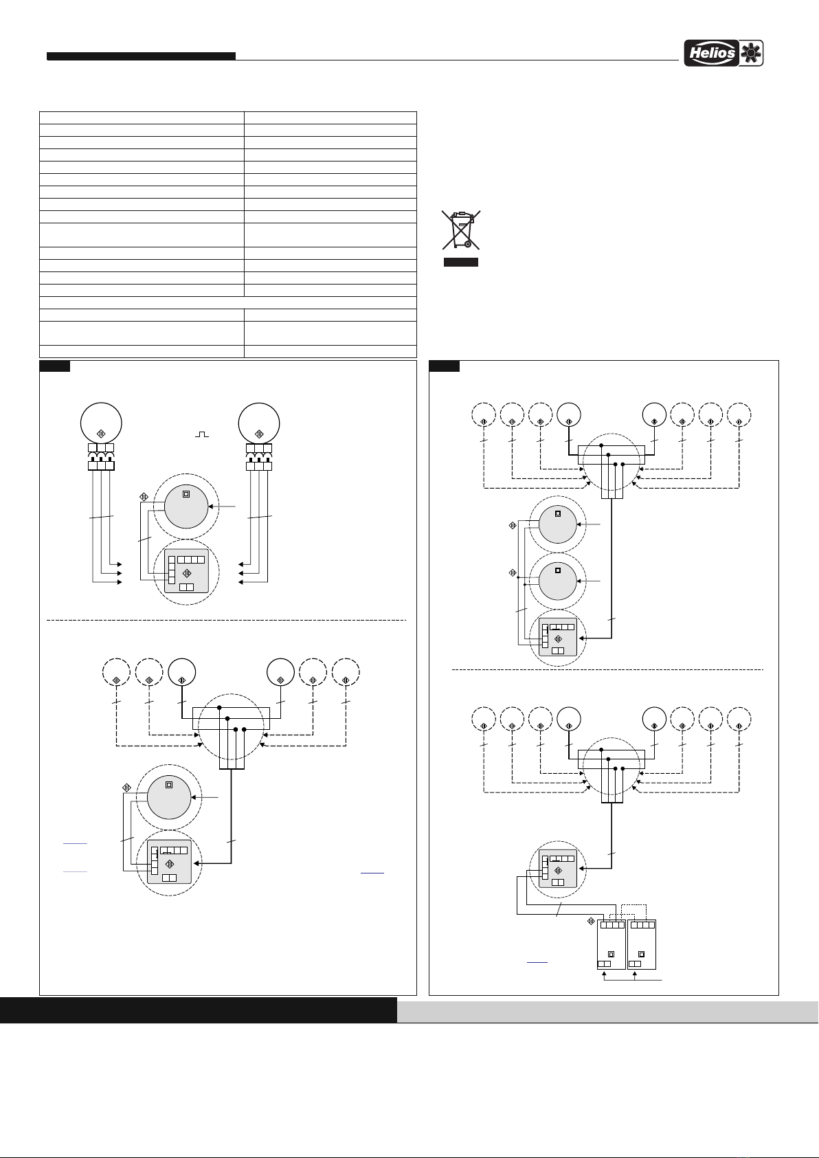
Das Netzteil ist nach Anschlussplan SS-1091 (1 Netzteil),
bzw. je nach Konfiguration SS-1093 (2 Netzteile parallel)
anzuschließen.
Achtung!
Auf der Netzteil Ausgangsseite ist ein Ferrit montiert.
Dieser ist Bestandteil des Netzteils und notwendig
um die korrekte Funktion sicherzustellen. Der Ferrit
darf nicht entfernt werden.
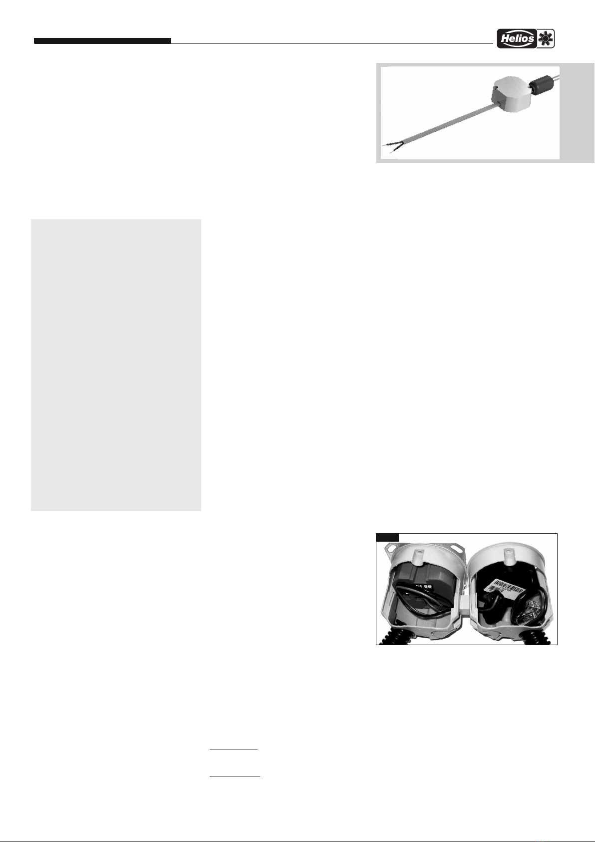
Die Eingangs- und Ausgangsleitungen sind abgesetzt
voneinander zu verlegen (s. Abb. 1). Den Ferrit möglichst
mit einem Abstand von ca. 1 cm hinter dem Netzteil plat-
zieren. Die Leitungen ohne Knäuel verlegen. Die Leitun-
gen dürfen sich nicht kreuzen und müssen entsprechend
gekürzt werden.
Alle Klemmstellen der Verdrahtung sind nach DIN EN
60998 einzusetzen.
Diese müssen für einen Temperaturbereich von 85 °C
und einer Spannung von 300 V ausgelegt sein.
Klemmen-Vorschlag: Wago Typ 221
Abb.1
Schaltnetzteil KWL 45 SNU
Montage- und Betriebsvorschrift
Service / Information
DELIOS Ventilatoren Gmb & Co KG · Lupfenstraße 8 · 78056 VS-Schwenningen
AELIOS Ventilatoren · Postfach 854 · Siemensstraße 15 · 6023 Innsbruck
FELIOS Ventilateurs · Le Carré des Aviateurs · 157 av. Charles Floquet · 93155 Le Blanc Mesnil Cedex
CH ELIOS Ventilatoren AG · Tannstrasse 4 · 8112 Otelfingen
GB ELIOS Ventilation Systems Ltd. · 5 Crown Gate · Wyncolls Road · Severalls Industrial Park · Colchester · Essex · CO4 9 Z
Als eferenz am Gerät griffbereit aufbewahren! Druckschrift-Nr. 82 402/11.16 www.heliosventilatoren.de
Abb.2
M1
Farbcode nach IEC 757
RD-rt- rot-red
BU-bl-blau-blue
VT-vi-violett-violett
rot / +12VDC
blau / - GND
violett / PWM
M2
KWL EC 45: M2 - Start Abluft
12
4
6
5
7
KWL 45 BEU
230 V~ /
12 V =
KWL 45 SNU
89
10
11
+
-
+
-
230 V~
UP-Dose
UP-Dose
Betrieb mit 2 x KWL EC 45 mit 1 x KWL 45 SNU
rt bl vi
8
6
10
rt bl vi
11
7
9
KWL EC 45: M1 - Start Zuluft
M1
KWL EC 45: Start Abluft
12
4
6
5
7
KWL 45 BEU
230 V~ /
12 V =
KWL 45 SNU
89
10
11
+
-
+
-
230 V~
UP-Dose
UP-Dose
Betrieb mit mehr als 2 bis 6 x KWL EC 45 mit 1 x KWL 45 SNU
KWL EC 45: Start Zuluft
Verteiler
4 max. 4 m bis zum Sternpunkt
- empfohlene Steuerleitung J-Y (ST) Y 0,8 mm
- max. Länge je Motor vom KWL 45 BEU bis zum Motor 30 m
- alle Motoren sternförmig zum Verteiler
- vom Verteiler / Sternpunkt bis zum KWL 45 BEU max. 4 m
M3
M5
M2 M4 M6
6
8
10 11
3
6 - GND
8 - + 12V
10 - PWM Start Zuluft
11 - PWM Start Abluft
3 3333
3
- empfohlene Steuerleitung J-Y (ST) Y 0,8 mm
- max. Länge je Motor vom KWL 45 BEU
bis zum Motor max. 30 m
3
1)
1)
Maximal 6 x KWL EC 45
möglich.
Für 8 Ventilatoren
2 x KWL 45 SNU
parallel schalten,
siehe
Alternativ mit
Hutschienen Netzteil,
siehe
SS-1093
SS-1093
85360 001 SS-1091 12.06.15
Weitere Anschlussvarianten siehe SS-1093
1,5 mm²,
max. 4 m
2
1,5 mm²,
max. 4 m
2
Abb.3
M1
KWL EC 45: Start Abluft
12
4
6
5
7
KWL 45 BEU
230 V~ /
12 V =
KWL 45 SNU
89
10
11
+
-
+
-
230 V~
UP-Dose
UP-Dose
Betrieb mit bis zu 8 x KWL EC 45 mit 2 x KWL 45 SNU parallel
KWL EC 45: Start Zuluft
Ve r te i le r
4 max. 4 m bis zum Sternpunkt
- empfohlene Steuerleitung J-Y (ST) Y 0,8 mm
- max. Länge je Motor vom KWL 45 BEU bis zum Motor 30 m
- alle Motoren sternförmig zum Verteiler
- vom Verteiler / Sternpunkt bis zum KWL 45 BEU max. 4 m
M3
M5
M2 M4 M6
6
8
10 11
3
6 - GND
8- + 12V
10 - PWM Start Zuluft
11 - PWM Start Abluft
3 3333
1)
1)
Für 8 Ventilatoren 2 x
KWL 45 SNU parallel
schalten (direkt neben
bzw. untereinander, ohne
Abstand)
85364 001 SS-1093 12.06.15
M7
M8
3
230 V~ /
12 V =
+
-
UP-Dose
1)
230 V~
KWL 45 SNU
3
- Betrieb mit bis zu 4 x KWL EC 45 mit 1 x KWL 45 SNH oder
- Betrieb mit bis zu 8 x KWL EC 45 mit 2 x KWL 45 SNH parallel
M1
KWL EC 45: Start Abluft
12
4
6
5
7
KWL 45 BEU
KWL 45 SNH
89
10
11
+
-
UP-Dose
KWL EC 45: Start Zuluft
Ve r te i le r
4 max. 4 m bis zum Sternpunkt
- empfohlene Steuerleitung J-Y (ST) Y 0,8 mm
- max. Länge je Motor vom KWL 45 BEU bis zum Motor 30 m
- alle Motoren sternförmig zum Verteiler
- vom Verteiler / Sternpunkt bis zum KWL 45 BEU max. 4 m
M3
M5
M2 M4 M6
6
8
10 11
3
6 - GND
8 - + 12V
10 - PWM Start Zuluft
11 - PWM Start Abluft
3 3333
bei 5-8 Ventilatoren
2 x KWL 45 SNH
parallel schalten
(nebeneinander ohne Abstand)
M7
M8
3 3
L N
+ + --
KWL 45 SNH
L N
+ + --
230 V~
1,5 mm², max. 30 m
2
Standardanschluss siehe SS-1091
1,5 mm²,
max. 4 m
2
Eingangsspannung 230 V AC / 0,24 A 50 / 60 z
Betriebsspannungsbereich 207-253 V AC 47-63 z
Ausgangsspannung 12,0 V DC / 1,9 A 23 W
Übertemperaturschutz integriert
Überlastschutz, Strombegrenzung > 2,5 A
Interne Primär-Sicherung 2 A/T
Externe Leitungsabsicherung 6-10 A
Verlustleistung Bereitschaft max. 0,5 W
Kurzschlussschutz ausgangsseitig, automatischer Neustart
Überspannungsschutz ausgangsseitig, einrastend,
Netzabschaltung erforderlich
Umgebungstemperaturbereich -5 °C bis +40 °C
maximale Oberflächentemperatur am Tc Punkt +85 °C
Relative Feuchtigkeit 5-95 % (nicht kondensierend)
Lagertemperatur -40 °C bis 85 °C
Sicherheit:
Eingangsseitig Schutzklasse II
Ausgangsseitig Schutzklasse III
Sicherheitskleinspannung SELV konform
Sicherheitszulassung nach EN60950-1 und EN60335-1
5.0 eparatur und Instandsetzung
GEFAH
Berührung von spannungsführenden Teilen führt zum elektrischen
Schlag. Vor allen Instandhaltungs- und Wartungsarbeiten allpolig vom
Netz trennen und gegen Wiedereinschalten sichern!
Für das Netzteil ist keine Wartung vorgesehen, bei Defekten ist es als Ganzes
zu ersetzen!
6.0 Entsorgung
Verpackungen sind sachgerecht zu entsorgen. Die elektrischen
Geräte sind an Sammelstellen für die Rücknahme von Elektro- und
Elektronikschrott abzugeben. Das ElektroG zur Entsorgung von
elektrischen Geräten findet hier keine Anwendung. Akkus und Bat-
terien sind gemäß § 12 der Batterieverordnung (BattV) an den er-
steller oder bei einer entsprechenden Sammelstelle abzugeben. Elektrische
Geräte, Akkus und Batterien dürfen nicht dem ausmüll zugeführt werden.
Schaltplan SS-1091 Schaltplan SS-1093
4.0 Technische Daten

1
Switching power supply KWL 45 NU
Installation and operating instructions
IN TALLATION AND OPERATING IN TRUCTION
NO. 82 402
1.0 Important information
In order to ensure complete and effective operation
and for your own safety, all of the following instruc-
tions should be read carefully and observed.
This document should be regarded as part of the
product and as such should be kept accessible
and durable to ensure the safe operation of the fan.
All plant-related safety regulations must be obser-
ved.
These installation instructions cannot take all Instal-
lation, operating and maintenance conditions into
account. You can obtain further information from
your local dealer or the product data sheet, which
can be downloaded on the internet.
1.1 afety instructions
Special regulations apply for use,
connection and operation; consultation is
required in case of doubt. Further infor-
mation can be found in the relevant stan-
dards and legal texts.
The following points must be ob-
served before any cleaning, mainten-
ance and installation work:
• Isolate device from the mains power
supply and secure against being swit-
ched on again!
• After switching off, a waiting time of
5 min. must be observed, as dange-
rous voltages may be present after di-
sconnection from the mains due to in-
ternal capacitors!
• Non-observance, touching live electri-
cal parts or improper use of this po-
wer supply unit can result in death,
serious injuries or significant material
damage.
• All plant-related safety regulations
must be observed!
Further country-specific regulations
must also be observed.
1.2 Application
This compact, fully encapsulated switching power
supply is solely designed as a decentral power
supply for the KWL EC 45 fan series for installation
in a flush-mounted box.
Further information can be found in section 3.0 “In-
stallation”.
– Normal use:
The KWL 45 SNU power supply unit is only appro-
ved for fixed installation inside buildings in a flush-
mounted box. The maximum permissible ambient
temperature can be found on the type plate.
– Reasonably foreseeable misuse:
The power supply unit is not suitable for operation
under difficult conditions, such as high levels of hu-
midity, aggressive media, long standstill periods,
heavy contamination, excessive loads due to clima-
tic, technical or electronic influences. The same ap-
plies for the mobile use of fans (vehicles, aircraft,
ships, etc.). Usage under these conditions is only
possible with release approval from Helios, as the
standard version is not suitable in this case.
– Improper, prohibited use:
Any use other than the intended use is not permit-
ted! The conveying of solid matter or solid matter
content > 10µm in air and liquid is not permitted!
1.4 Personnel qualification
DANGER!
The electrical connection and start-up must on-
ly be carried out by qualified electricians.
Installation, servicing and maintenance of the
fan must only be carried out by qualified elec-
tricians. EcoVent Verso individual room ventilation
units can be used by children over the age of 8 as
well as persons with physical, sensory, or mental
disabilities or lack of experience and knowledge, if
they are supervised or instructed with regard to the
safe use of the unit and they understand the resul-
ting risks. Children must not play with the unit.
Cleaning or user maintenance must not be carried
out by unsupervised children.
1.4 cope of delivery
The delivery includes the switching power supply
KWL 45 NU / Ref.no.: 3008
2.0 Warranty claims – exclusion of liability
If the following instructions are not observed, our
warranty shall be invalidated. The same applies
to liability claims against Helios. The use of ac-
cessory parts, which are not recommended or
offered by Helios, is not permitted. Any possible
damages are not covered by the warranty.
2.1 Certificates - guidelines
If the product is installed correctly and used to its
intended purpose, it conforms to all applicable
EU guidelines at its date of manufacture.
2.2 hipping
The power supply unit is packed ex works in
such a way that it is protected against normal
transport strain. Carry out the shipping carefully.
It is recommended to leave the power supply
unit in the original packaging.
2.3 Receipt
The shipment must be checked for damage and
correctness immediately upon delivery. If there is
any damage, promptly report the damage with
the assistance of the transport company.
If complaints are not made within the agreed pe-
riod, any claims could be lost.
3.0 Installation
- During operation, the power supply unit must
not be accessible.
- A suitable flameproof casing must be provided
in the end product.
- Sufficient cooling must be ensured.
- The maximum surface temperature at the Tc
point must not be exceeded.
The casing fulfils the requirements of IP 67 and it
is fully protected against dust and penetrating
humidity.
The power supply units are intended for installa-
tion in deep (61 mm) flush-mounted boxes with
a 68 mm diameter (fire resistance 850 °C accor-
ding to VDE 0606).
The connection can be made via the connecting
wires with suitable terminals.
Connecting cables:
Input side: 0.8 mm² (black - white)
with outer sheath,
wire end ferrule
Output side: 0.52 mm² (black - red)
tin-plated
3.1 Electrical connection / start-up
DANGER
Touching live parts will result in electric shock.
Only connect with no voltage present!
– The electrical connection and initial start-up are to be
carried out in accordance with the relevant wiring dia-
grams and are only to be carried out by a certified
electrician.
–The relevant standards, safety regulations (e.g. DIN
VDE 0100, EN 50178), as well as the technical con-
nection conditions of energy suppliers are to be adhe-
red to!
– A multipole mains section switch/isolator, with a mini-
mum contact opening of 3 mm (VDE 0700 T1 7.12.2 /
EN 60335-1) is mandatory!
– The power supply and the supply network must be suf-
ficiently fused.
– The network connection must comply with IEC 62103,
EN 50178 and IEC 60364, VDE 100
– Network configuration, voltage and frequency must be
consistent with the rating plate information.
– The supply line must be introduced, so that no water
can get in along the cable in case of water exposure.
– Never work on the power supply unit when it is live!
There is a risk of electric arcs and electric shock which
can result in death, serious injuries or significant mate-
rial damage.
Warning:
Dangerous voltages and components with significant
amounts of stored energy may be present during normal
power supply unit operating conditions. However, they
are not accessible.
Improper use can result in electrical shock or signifi-
cant burns! Keep away from fire and water!
The power supply unit must be connected according to
wiring diagram SS-1091 (1 power supply unit), or SS-
1093 (2 parallel power supply units) depending on the
configuration.
Attention!
A ferrite is mounted on the output side of the power
supply unit. This is a component of the power supply
unit and it is required to ensure correct functionality.
The ferrite must not be removed.
The input and output cables must be installed so that
they are clearly separated from one another (see Fig. 1).
Ideally, position the ferrite at a distance of approximately
1 cm behind the power supply unit. Install the cables wi-
thout twisting. The cables must not cross each other and
must be shortened accordingly.
All wiring terminals must comply with DIN EN 60998.
These terminals must be designed for a temperature ran-
ge from 85 °C and a voltage of 300 V.
Terminal recommendation: Wago Type 221
fig.1

Switching power supply KWL 45 NU
Installation and operating instructions
ervice / Information
DHELIOS Ventilatoren mbH & Co · Lupfenstraße 8 · 78056 VS-Schwenningen
AHELIOS Ventilatoren · Postfach 854 · Siemensstraße 15 · 6023 Innsbruck
FHELIOS Ventilateurs · Le Carré des Aviateurs · 157 av. Charles Floquet · 93155 Le Blanc Mesnil Cedex
CH HELIOS Ventilatoren A · Tannstrasse 4 · 8112 Otelfingen
GB HELIOS Ventilation Systems Ltd. · 5 Crown ate · Wyncolls Road · Severalls Industrial Park · Colchester · Essex · CO4 9HZ
Please keep this manual for reference with the unit! Print-No. 82 402/11.16 www.heliosventilatoren.de
fig.2
M1
Farbcode nach IEC 757
RD-rt- rot-red
BU-bl-blau-blue
VT-vi-violett-violett
rot / +12VDC
blau / - GND
violett / PWM
M2
KWL EC 45: M2 - Start Abluft
12
4
6
5
7
KWL 45 BEU
230 V~ /
12 V =
KWL 45 SNU
89
10
11
+
-
+
-
230 V~
UP-Dose
UP-Dose
Betrieb mit 2 x KWL EC 45 mit 1 x KWL 45 SNU
rt bl vi
8
6
10
rt bl vi
11
7
9
KWL EC 45: M1 - Start Zuluft
M1
KWL EC 45: Start Abluft
12
4
6
5
7
KWL 45 BEU
230 V~ /
12 V =
KWL 45 SNU
89
10
11
+
-
+
-
230 V~
UP-Dose
UP-Dose
Betrieb mit mehr als 2 bis 6 x KWL EC 45 mit 1 x KWL 45 SNU
KWL EC 45: Start Zuluft
Verteiler
4 max. 4 m bis zum Sternpunkt
- empfohlene Steuerleitung J-Y (ST) Y 0,8 mm
- max. Länge je Motor vom KWL 45 BEU bis zum Motor 30 m
- alle Motoren sternförmig zum Verteiler
- vom Verteiler / Sternpunkt bis zum KWL 45 BEU max. 4 m
M3
M5
M2 M4 M6
6
8
10 11
3
6 - GND
8 - + 12V
10 - PWM Start Zuluft
11 - PWM Start Abluft
3 3333
3
- empfohlene Steuerleitung J-Y (ST) Y 0,8 mm
- max. Länge je Motor vom KWL 45 BEU
bis zum Motor max. 30 m
3
1)
1)
Maximal 6 x KWL EC 45
möglich.
Für 8 Ventilatoren
2 x KWL 45 SNU
parallel schalten,
siehe
Alternativ mit
Hutschienen Netzteil,
siehe
SS-1093
SS-1093
85360 001 SS-1091 12.06.15
Weitere Anschlussvarianten siehe SS-1093
1,5 mm²,
max. 4 m
2
1,5 mm²,
max. 4 m
2
fig.3
M1
KWL EC 45: Start Abluft
12
4
6
5
7
KWL 45 BEU
230 V~ /
12 V =
KWL 45 SNU
89
10
11
+
-
+
-
230 V~
UP-Dose
UP-Dose
Betrieb mit bis zu 8 x KWL EC 45 mit 2 x KWL 45 SNU parallel
KWL EC 45: Start Zuluft
Ve r te i le r
4 max. 4 m bis zum Sternpunkt
- empfohlene Steuerleitung J-Y (ST) Y 0,8 mm
- max. Länge je Motor vom KWL 45 BEU bis zum Motor 30 m
- alle Motoren sternförmig zum Verteiler
- vom Verteiler / Sternpunkt bis zum KWL 45 BEU max. 4 m
M3
M5
M2 M4 M6
6
8
10 11
3
6 - GND
8- + 12V
10 - PWM Start Zuluft
11 - PWM Start Abluft
3 3333
1)
1)
Für 8 Ventilatoren 2 x
KWL 45 SNU parallel
schalten (direkt neben
bzw. untereinander, ohne
Abstand)
85364 001 SS-1093 12.06.15
M7
M8
3
230 V~ /
12 V =
+
-
UP-Dose
1)
230 V~
KWL 45 SNU
3
- Betrieb mit bis zu 4 x KWL EC 45 mit 1 x KWL 45 SNH oder
- Betrieb mit bis zu 8 x KWL EC 45 mit 2 x KWL 45 SNH parallel
M1
KWL EC 45: Start Abluft
12
4
6
5
7
KWL 45 BEU
KWL 45 SNH
89
10
11
+
-
UP-Dose
KWL EC 45: Start Zuluft
Ve r te i le r
4 max. 4 m bis zum Sternpunkt
- empfohlene Steuerleitung J-Y (ST) Y 0,8 mm
- max. Länge je Motor vom KWL 45 BEU bis zum Motor 30 m
- alle Motoren sternförmig zum Verteiler
- vom Verteiler / Sternpunkt bis zum KWL 45 BEU max. 4 m
M3
M5
M2 M4 M6
6
8
10 11
3
6 - GND
8 - + 12V
10 - PWM Start Zuluft
11 - PWM Start Abluft
3 3333
bei 5-8 Ventilatoren
2 x KWL 45 SNH
parallel schalten
(nebeneinander ohne Abstand)
M7
M8
3 3
L N
+ + --
KWL 45 SNH
L N
+ + --
230 V~
1,5 mm², max. 30 m
2
Standardanschluss siehe SS-1091
1,5 mm²,
max. 4 m
2
Input voltage 230 V AC / 0,24 A 50 / 60 Hz
Operating voltage range 207-253 V AC 47-63 Hz
Output voltage 12.0 V DC / 1.9A 23 W
Integrated overtemperature protection
Overload protection, current limiter > 2.5 A
Internal primary fuse 2 A/T
External line fuse 6-10 A
Power loss standby max. 0.5 W
Short-circuit protection Output side, automatic restart
Overvoltage protection Output side, snap-in,
mains disconnection required
Ambient temperature range -5 °C to +40 °C or
Maximum surface temperature at Tc point +85 °C
Relative humidity 5-95 % (non-condensing)
Storage tempature -40 °C to 85 °C
afety:
Input side Protection class II
Output side Protection class III
Safety extra-low voltage SELV compliant
Safety approval acc. to EN60950-1 and EN60335-1
5.0 Repair and maintenance
DANGER
The touching of live electrical parts can cause an electrical shock. Iso-
late device from the mains power supply and secure against being
switched on again!
Maintenance is not provided for the power supply unit and the unit must be
fully replaced in case of defects!
6.0 Disposal
Packaging must be correctly disposed of. The electrical devices
must be returned to collection points for the recovery of electrical
and electronic waste. The Electrical and Electronic Equipment Act
for the disposal of electrical devices is not applicable. According to
§ 12 of the Battery Directive (BattV), accumulators and batteries
must be returned to the manufacturer or an appropriate collection point.
Electrical devices, accumulators and batteries may not be disposed of with
household waste.
Circuit diagram -1091 Circuit diagram -1093
4.0 Technical data

1
Transformateur KWL 45 SNU
Notice de montage et d’utilisation
NOTICE DE MONTAGE ET D’UTILISATION
N° 82 402
1.0 Informations importantes
Il est important de bien lire et suivre l’ensemble des
consignes suivantes pour le bon fonctionnement
de l’appareil et pour la sécurité des utilisateurs.
Conserver soigneusement le document comme ré-
férence à proximité de l’appareil, afin d’assurer une
bonne utilisation du transformateur.
Cette notice d’installation ne contient pas toutes les
consignes pour l’installation, l’utilisation et la main-
tenance. Des informations supplémentaires se
trouvent chez votre vendeur ou sur la fiche produit,
téléchargeable sur Internet.
1.1 Consignes de sécurité
Pour le fonctionnement, le raccordement
et l’utilisation, contacter Helios en cas de
doutes. Des informations supplémen-
taires sont consultables dans les normes
et textes de loi.
Avant tous travaux d’entretien, de
maintenance et d’installation, vérifier
les points suivants :
• Veiller à ce que l’appareil soit hors
tension et protégé contre tout
redémarrage intempestif !
• Avant d’intervenir, un temps d’attente
de env. 5 min est à respecter après la
coupure, car les condensateurs
internes peuvent présenter des
tensions dangereuses malgré la
coupure de courant !
• L’inattention, le contact avec les
parties sous tensions ou l’utilisation
inappropriée du réseau peuvent
entraîner la mort, des blessures
graves et des dégâts matériaux
importants.
• Respecter toutes les consignes de
sécurité !
Respecter la conformité avec les
normes nationales en vigueur.
1.2 Domaine d’utilisation
Ce transformateur compact entièrement scellé est
exclusivement conçu comme alimentation élec-
trique décentralisée pour la série de ventilateurs
KWL EC 45 destinée à un montage encastré. Des
détails supplémentaires sont à consulter section
3.0 „ Installation”.
– Utilisation conforme :
Le transformateur 45 SNU est conçu uniquement
pour une installation fixe en bâtiment encastrée. La
température d’ambiance max. indiquée sur la
plaque signalétique est à respecter.
– Utilisation envisageable mais non conseillée :
En cas de fonctionnement dans des conditions ex-
trêmes, comme par exemple avec une humidité
élevée, un taux élevé de particules agressives, des
phases d’arrêt longues, un encrassement impor-
tant, un usage intensif lié aux conditions clima-
tiques ou soumis à des contraintes techniques et
électroniques, une demande d’approbation est re-
quise par Helios : les modèles de série n’étant pas
prévus pour cet usage. Idem pour le déplacement
des ventilateurs (voitures, avions, bateaux, etc.).
– Utilisation abusive, interdite :
Tout usage inapproprié n’est pas autorisé ! L’utilisa-
tion en zone explosive n’est pas permise.
1.3 Qualification du personel
DANGER !
Les raccordements électriques et les mises
en service électroniques ne doivent être ef-
fectués que par des électriciens qualifiés.
Les travaux d’installation, de maintenance et
d’entretien ne doivent être effectués que par
du personnel qualifié et certifié.
Les EcoVent Verso peuvent être utilisés par des
personnes (y compris les enfants à partir de 8
ans) dont les capacités physiques, sensorielles
ou mentales sont réduites ou qui manquent
d’expérience et de connaissance, sous sur-
veillance ou s’ils sont conscients de l’utilisation
appropriée du ventilateurs et de ses dangers po-
tentiels. Le ventilateur n’est pas un jouet. L’en-
tretien et la maintenance ne peuvent être effec-
tués par un enfant sous surveillance.
1.4 Contenu de la livraison
La livraison contient le transformateur
KWL 45 SNU / Réf. n° : 3008
2.0 Demande de garantie - Réserves du
constructeur
Si toutes les consignes indiquées dans cette no-
tice ne sont pas correctement respectées, la ga-
rantie s’annule. Idem pour les réserves construc-
teur. L’utilisation d’accessoires, non conseillés
ou proposés par Helios, la garantie s’annule.
Les dégâts éventuels causés par cette utilisation
ne sont pas pris en charge.
2.1 Réglementations – Normes
Cet appareil est conforme aux directives CE en
vigueur le jour de sa fabrication et sous d’une ré-
serve d’une utilisation appropriée.
2.2 Transport
Le transformateur est emballé en usine et est
protégé des dégâts de transport courants.
Transporter l'appareil avec soin. Il est préférable
de laisser l'appareil dans son emballage d'origi-
ne jusqu'au montage sur site.
2.3 Réception de la marchandise
Dès réception, vérifier l’état et la conformité du
matériel commandé. En cas d’avaries, des ré-
serves doivent être portées sur le bordereau du
transporteur. Elles doivent être précises, significa-
tives, complètes et confirmées par lettre recom-
mandée au transporteur. Attention, le non-res-
pect de ces procédures peut entraîner le rejet de
la réclamation.
3.0 Installation
- Pendant le fonctionnement, le bloc d'alimenta-
tion ne peut être accessible.
- Un boîtier ignifuge approprié doit être prévu
dans le produit fini.
- Un refroidissement suffisant doit être assuré.
- La température de surface maximale ne peut
pas être dépassée.
Le boîtier répond aux exigences IP 67 et est en-
tièrement protégé contre la poussière et la péné-
tration d'humidité.
Les blocs d'alimentation sont destinés à être
montés (61 mm) dans des boîtiers encastrés de
68 mm de diamètre (résistance au feu à 850 °C
selon VDE 0606).
La connexion peut se faire au moyen de fils de
raccordement avec les bornes appropriées.
Raccordements électriques :
Entrée primaire : 0,8 mm² (noir - blanc)
avec manteau externe,
embouts de câbles montés.
Sortie secondaire : 0,52 mm² (noir - rouge)
étamé.
3.1 Raccordement électrique/Mise en service
DANGER
Tout contact avec des parties sous tension peut en-
traîner un choc électrique.
Le raccordement doit se faire hors tension !
– Le raccordement électrique et la première
mise en service ne doivent être effectués que
par un électricien autorisé selon les schémas
de raccordement correspondants.– Respecter
les normes et consignes de sécurité
correspondantes (DIN VDE 0100, EN 50178, par ex.)
ainsi que les conditions techniques de raccordement
des fournisseurs d’électricité !
– Un disjoncteur/interrupteur de révision, avec une
ouverture de contact de 3 mm min. (VDE 0700 T1
7.12.2 / EN 60335-1) est impératif !
–L’alimentation et le réseau d’alimentation doivent être
suffisamment protégés.
– Le raccordement réseau doit être conforme aux
normes IEC 62103, EN 50178 et IEC 60364, VDE 100.
– Réseau, tension et fréquence doivent correspondre
aux données de la plaque signalétique.
– Le passage des câbles ne doit permettre aucune
infiltration lors de projections d’eau.
– Ne jamais toucher au câblage sous tension ! Cela
pourrait entraîner des arcs et chocs électriques
mortels, des blessures graves et dégâts matériaux
importants.
Avertissement :
De dangereuses tensions et les composants contenant
une importante quantité d’énergie cumulée peuvent ap-
paraître dans des conditions normales d’utilisation. Ce-
pendant, ils ne sont pas accessibles.
Une manipulation inappropriée peut entraîner des
chocs électriques et brûlures ! Tenir éloigner de l’eau
et du feu !
Le réseau est à raccorder selon les plans SS-1091 (1 ré-
seau), et selon la configuration SS-1093 (2 réseaux pa-
rallèles).
Danger !
Une ferrite est montée sur la sortie secondaire. Elle
fait partie du bloc d'alimentation et est nécessaire
pour assurer son fonctionnement correct. La ferrite
ne peut être retirée.
Les câbles d’entrée et de sortie doivent être posés sé-
parément l’un de l’autre. Installer la ferrite d’antiparasita-
ge électromagnétique à environ 1 centimètre derrière
l’alimentation. Raccourcir les câbles à la bonne longueur
et les poser sans nœuds et sans les croiser.
Les bornes de raccordement des câblages doivent être
utilisées selon la norme EN 60998.
Les connecteurs sont dimensionnés pour une plage de
température de 85°C et une tension de 300 V. Sugges-
tion de connecteurs : WA O 221.
Fig.1
Table of contents
Languages:
Other Helios Power Supply manuals

Helios
Helios KWL-KS WE User manual

Helios
Helios ICT Platinum Series User manual

Helios
Helios SR250HL User manual

Helios
Helios Salicru EMi3 User manual

Helios
Helios HPS-PS-STANDALONE-SR100HL User manual

Helios
Helios AS-P-601 User manual

Helios
Helios KWL 45 SNU User manual

Helios
Helios SR500L Series User manual

Helios
Helios SR100A User manual

Helios
Helios SR250A User manual


Popular Power Supply manuals by other brands

Videx
Videx 520MR Installation instruction

Poppstar
Poppstar 1008821 Instructions for use

TDK-Lambda
TDK-Lambda LZS-A1000-3 Installation, operation and maintenance manual

TDK-Lambda
TDK-Lambda 500A instruction manual

Calira
Calira EVS 17/07-DS/IU operating instructions

Monacor
Monacor PS-12CCD instruction manual


