Helios ICT Platinum Series User manual

Instruction Manual
855-339-001
Australia: [email protected] - Middle East & Asia: [email protected] - New Zealand: [email protected]
Your DC Power Solutions Partner

www.heliosps.com
2
Rev 1.0
Nov 2019

ZZZKHOLRVSVFRP
Table of Contents
1. PRODUCT DESCRIPTION ...................................5
2. INSTALLATION ....................................................6
2.1. Initial Inspection 6
2.2. Back-up Battery 7
2.3. Installation 8
2.4. Remote Control and Monitoring Connections 10
3. FRONT PANEL CONTROL ................................11
3.1. Control Panel Keys and Controls 11
3.2. Setting the DC Output 12
3.3. Control Panel Menus 13
3.4. Control Panel Menu Password Reset 22
3.5. Administrator Password / IP Address Reset 22
4. SMART PARALLEL OPERATION ............................23
4.1. SHARE Interface Connector 24
4.2. Configuring the Power Supplies for Parallel Operation 24
4.3. Connecting the Power Supplies in Parallel 25
4.4. Advanced Parallel Operation with TCP/IP Ethernet
Connection 27
4.5. Changing a Power Supply Back To a Standalone Unit 28
5. TCP/IP WEB BASED UTILITY ...........................29
5.1. System 31
5.2. Battery Backup 32
5.3. Alarms 37
5.4. Communications 39
5.5. Network Setup 40
5.6. Email Setup 43
5.7. User Setup 44
5.8. Maintenance 45
5.9. Router Configuration 46
5.10. Text Message Alarm Notifications 49
5.11. Network Troubleshooting 49
6. PRODUCT SPECIFICATION ..............................52
7. LIMITED WARRANTY ........................................54

www.heliosps.com
4
WARNING! – IMPORTANT SAFETY
NOTICES
Risk of personal injury and property damage! You must exercise
caution and follow the safety requirements listed below when
using your Platinum Series power supply.
•The Platinum Series Power supply is intended for installation and
use in a Restricted Access Location, such as a 19” equipment
rack
•Installation, operation, and service to be conducted by
qualified/trained service personnel only, with all wiring done in
accordance with local electrical codes
•Ensure the power supply is operated from a standard 3-pin
120VAC or 240VAC 50 / 60Hz outlet with proper grounding
connection
•Use 14AWG/1.5mm2or larger wiring for AC power and bonding
connections
•Building power supply circuit must have a circuit breaker with
maximum 20A rating for short circuit protection
•Ensure dc polarities and rated voltages are correct for both the
load and battery connections to the unit
•Ensure all connections are properly tightened before powering up
the unit to avoid over heating of connectors
•Disconnect all power sources (input power cord, and any
external batteries) before attempting any service activity. Internal
circuits can be energized with the power switch in the off position
•Battery current through the “+BAT” terminal and internal LVD
relay must not exceed the maximum current limit rating of the
Platinum Series power supply. Use a suitably rated over current
protection device and disconnect in line with the “+BAT” terminal
and external battery positive. Do not connect the “+BAT” terminal
of multiple units in parallel
•Do not connect any battery when more than one Platinum Series
Power supply is connected in parallel.
•Always consult with battery manufacturer and observe all battery
manufacturer recommendations

ZZZKHOLRVSVFRP 5
1. PRODUCT DESCRIPTION
ICT Platinum Series DC power supplies provide high efficiency in a
space-saving 1U rack mount design with power factor corrected AC
input and extremely low noise output for powering wireless
communications, broadband, and radio access equipment where high
reliability is essential. The Platinum Series has the ability to function
either as a standalone DC power supply or as a complete DC power
system when using the optional Battery Backup feature. Standard
TCP/IP based Ethernet monitoring with Smart Parallel operation for
up to 9.6kW of combined output power and control, with optional
battery backup, programmable charge parameters, and adjustable
LVD provide full featured DC power capability.
Platinum Series Features:
•Up to 1600W in a space saving 1RU rack mount design with 90-
93% typical efficiency over a broad power range
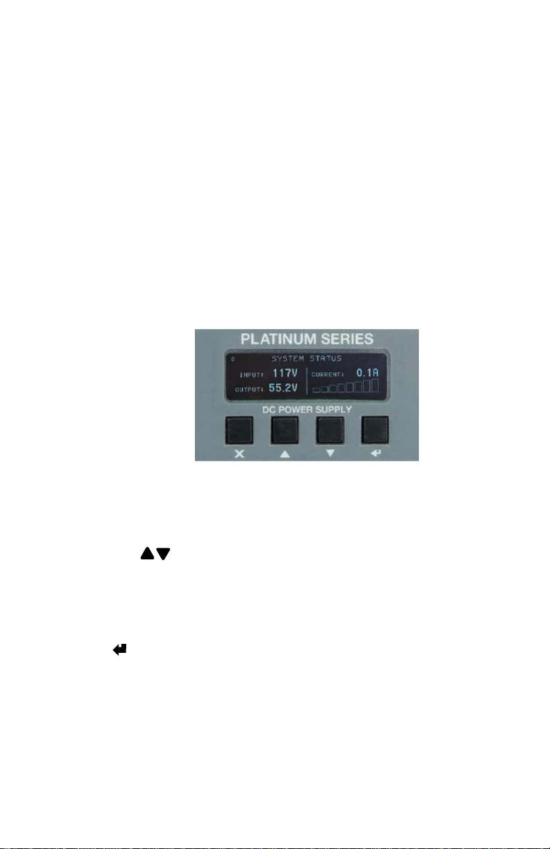
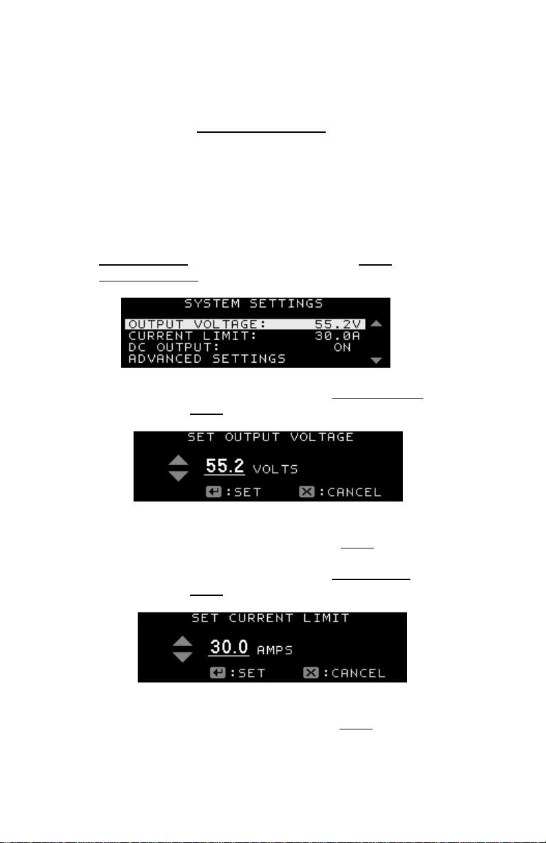
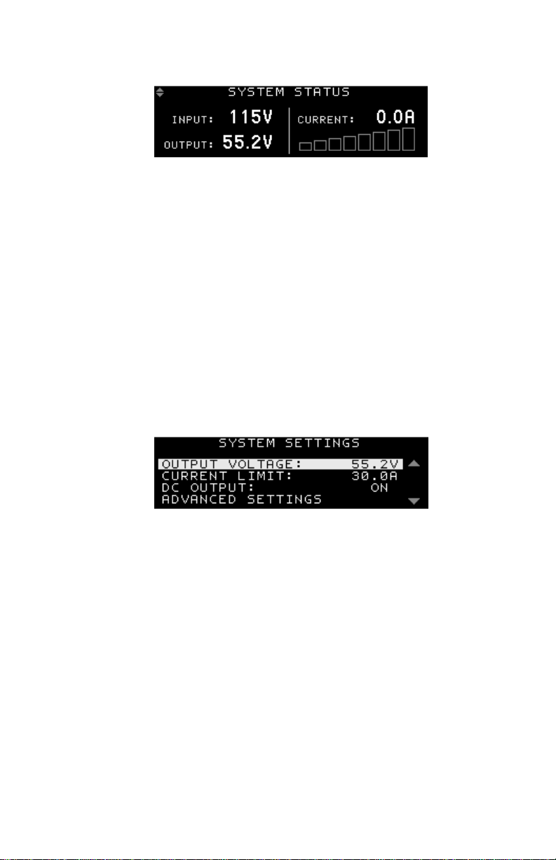
•Output voltage can be easily and accurately adjusted over
standard battery operating voltage ranges using the Intelligent
Power Control interface on the front panel
•Standard Ethernet port included for easy-to-use full featured
remote monitoring and control of the power supply using its built-
in web server, or via an SNMP management system
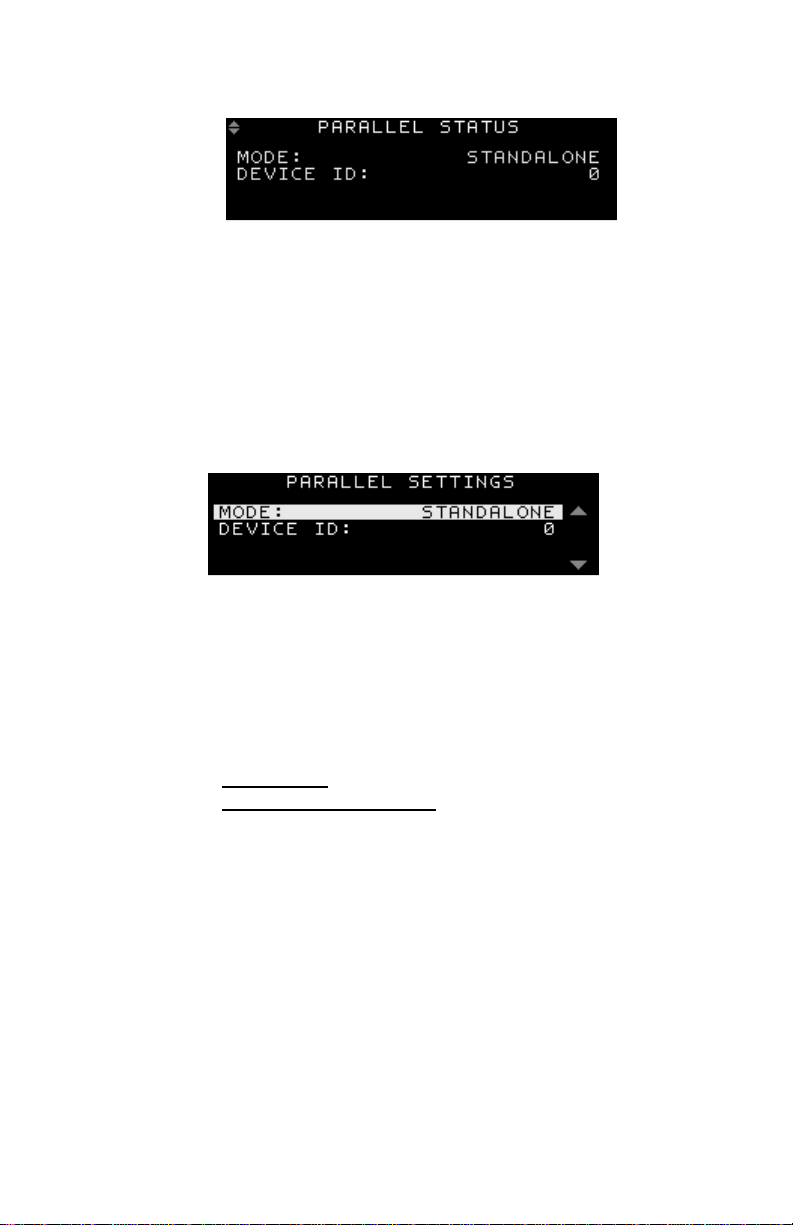
•Smart Parallel operation allows up to six Platinum Series power
supplies to be quickly and easily connected in parallel for up to
9.6kW of nominal power output
•Power Factor Corrected wide range AC input for maximum
flexibility, lowest supply current requirement, and economical
operation
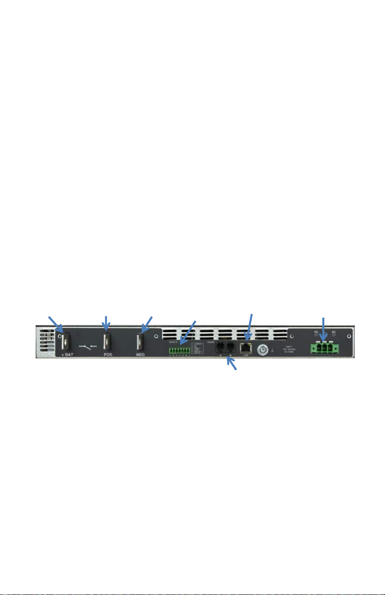
•Isolated design allows operation with positive or negative ground
•-30 to +70C operating temperature range
•Form C contacts for remote alarm signal
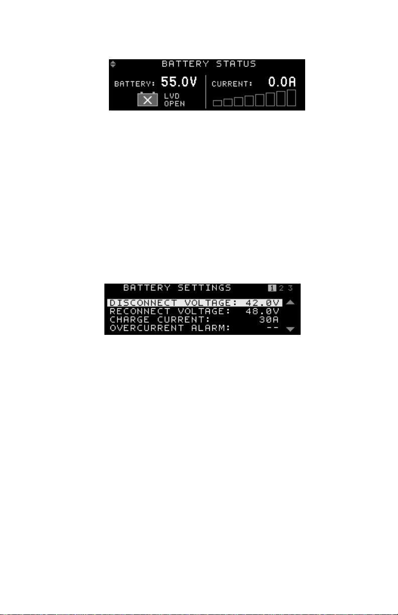
•Optional factory installed battery backup feature with battery
current monitor, LVD contactor (on battery Positive lead) with
adjustable voltage and charge rate set points, auto/manual
equalize charge, and temperature compensated charge voltage
with optional remote battery temperature sensor (ICT-TMP)

www.heliosps.com
6
Model Numbers and Options:
Note: The dedicated Battery Backup feature with LVD option is
designated by the suffix “B” (e.g. ICT1600-12SBC). The Australasian
models are designated by the letter “A” (e.g. ICT1600A-48SC).
2. INSTALLATION
2.1. Initial Inspection
Perform a quick physical check on the unit once it has been taken out
of the box to confirm it has not been damaged in shipping, and then
check for the included parts and accessories.
Your Platinum Series unit comes complete with:
•AC input wire clamp input connector plug (3pin), and 7 pin
REMOTE connector plug
•DC output bus bar cover and mounting hardware (installed)
•Two (Three with “B” option) Bus bar bolts with locking nuts for
output wiring
•Two rack mounting ears and hardware to mount to the power
supply chassis (installed)
•Instruction Manual
Model Watts
(Max)
Input
VAC
Output
VDC
Output
(A) Description
ICT1600-12SC 1600 90-300 11.5 - 15.5 120 12VDC 120A
Power Supply
ICT1600-24SC 1600 90-300 23.0 - 31.0 60 24VDC 60A
Power Supply
ICT1600-48SC 1600 90-300 46.0 - 62.0 30 48VDC 30A
Power Supply
ICT800-12SC 800 90-300 11.5 – 15.5 60 12VDC 60A
Power Supply
ICT800-24SC 800 90-300 23.0 – 31.0 30 24VDC 30A
Power Supply
ICT800-48SC 800 90-300 46.0 – 62.0 15 48VDC 15A
Power Supply

ZZZKHOLRVSVFRP 7
2.2. Back-up Battery
Anexternal lead-acid battery with the same nominal voltage as the
power supply may be connected directly in parallel with the output
terminals, or to the +BAT terminal (on units with the LVD option “B”)
to provide a DC backup capability. Use appropriate wire, over
current protection and disconnect device as outlined in the
Installation section. Your load will then be instantly powered from
the external battery if the AC input power should fail, and the battery
will recharge from the supply output when the AC power returns.
Choose your battery size (Ahr capacity) so that it can provide power
to the connected loads for the duration of a typical loss of AC power.
For both battery configurations the external battery will be charged
with a constant current (may be up to the supply output current
setting) until the float voltage (supply output voltage setting) is
reached, and then will be held at a constant float voltage as long as
the Platinum Series power supply is powered on. The maximum
battery charge current from the optional BAT port can be set
independently from the main output current limit.
WARNING!
Potential for personal injury, or damage to property and
equipment due to overcharging of the external battery!
The supply output voltage must be set to a voltage level suitable
for the external battery used. Check the float voltage rating of
your battery and set the supply output voltage accordingly
before connecting the battery to the system.
The battery may be charged at a rate up to the maximum output
current rating of the power supply. Ensure the battery used is
capable of being charged at this rate.
Do not connect any battery when more than one Platinum Series
Power supply is connected in parallel
If the AC power fails during normal operation the battery will remain
directly connected to the output through the LVD contactor and will
power the load with no delay or transition time. As battery voltage
falls to the LVD disconnect level (user adjustable) the LVD contactor
will open to help protect the battery from excessive discharge. The
contactor will re-close once the battery voltage rises again to the LVD
Reconnect threshold (user adjustable) due to charging from either an

ZZZKHOLRVSVFRP
8
external source, or from the unit when AC power is returned to the
power supply.
Note that during battery operation with AC power off the front panel
display backlight will shut off in a shorter time when not in use
(approx. 1 minute) to help minimize power loss. All other control and
communication functions will operate normally.
Use the optional battery temperature sensor (ICT-TMP) available
from ICT to compensate the charge voltage so that hot batteries are
not overcharged, and cold batteries receive adequate charge.
2.3. Installation
The ICT Platinum Series Power Supply is designed to be used in an
industry standard 19” rack mount cabinet or other restricted access
location. Insert the unit at the desired rack height, and secure using
four standard rack nuts and bolts (not provided). After the unit is
mounted, connect the load, battery, and supply wiring as outlined in
the steps below. Refer to the back panel illustration in Figure1 for
connector locations:
Figure 1: Back Panel Connectors (“SBC” model shown)
•Connect the positive side of the load to the ”POS” busbar and
the negative side of the load to the ”NEG” busbar using
suitable wire, ring-tongues and supplied hardware. Make sure
to tighten the busbar hardware to properly secure the wires.
•If applicable, on units with the Battery Backup (LVD) option
installed connect the POSITIVE of the backup battery to the
“+BAT” busbar and the negative of the backup battery to the
“NEG“ busbar using suitable wire, over current protection (a
fuse or circuit breaker in the battery positive lead), disconnect
device and hardware.
Battery + + Output Negative
AC Input
(AC
-
Gnd
-
AC)
Network
Remote
(Pin 1 to 7)
Primary- econdary hare Ports

ZZZKHOLRVSVFRP 9
CAUTION!
The internal LVD contactor ties the “+BAT” terminal to the
power supply “POS” output.
When using the LVD option in a positive ground system do not
ground the positive terminal of the battery. The system must only
have a single ground connection, normally located at the distribution
or load point. An additional ground connection at the battery will allow
current to bypass the internal LVD contactor preventing
disconnection of the battery during a low voltage event.
WARNING!
Battery current through the “+BAT” terminal must not exceed
the maximum current limit rating of the Platinum Series power
supply. Connect the “+BAT” terminal to the external battery
POSITIVE using a suitably rated over current protection and
disconnect device.
Otherwise damage to the unit, load, battery, and personal injury
may occur if the battery is inadvertently connected in reverse
polarity, or the output circuit is over loaded or shorted.
•Connect a chassis bonding wire to the ¼ inch ground stud
located on the back panel, if required, using 14AWG/1.5mm2
or larger wire to bond the power supply chassis to the
external rack system for the installation.
•Connect appropriately rated non-energized AC power wiring
to the removable AC input connector terminal plug. (AC line
or neutral to either outer connection, safety ground to the
middle pin) using 14AWG/1.5mm2or larger wire. Secure the
plug to the chassis by tightening the two captive retaining
screws.
•Connect the unit to a properly grounded non-energized AC
source capable of handling the rated Platinum Series input
current. The building supply circuit must have a branch rated
circuit breaker rated 20A or less.

ZZZKHOLRVSVFRP
10
2.4. Remote Control and Monitoring Connections
Make connections to the removable 7 pin cage clamp style REMOTE
connector for the following functions:
CAUTION!
Ensure unit is off and power is disconnected prior to making
connections to the REMOTE connector terminals to avoid
damaging the power supply or connected devices.
•Connect external alarm monitoring input wiring to the Alarm
Output contacts on the REMOTE connector to enable the
internal Alarm relay contact closure to flag an external
monitoring system for a power supply fault condition. (See
section 5.5 Alarm Setup, for details on which fault conditions
will trip the Alarm Output contacts).
•Connect the optional remote battery temperature monitor probe
(ICT-TMP) (for use on optional “B” LVD equipped models) to
pin 4 and 5, to automatically compensate the charging voltage
according to the battery temperature. Apply the probe body to
the side of the middle battery case using the provided adhesive
backed clamp. (note that the compensation level must be set
via the Battery Configuration page on the Network Utility or the
front Battery Settings screen to activate)
•Connect external Remote Shutdown control lines (TTL
compatible signal) to the REM SD+ (pin 6) and REM SD- (pin
7) terminals of the “REMOTE” connector if external on/off
control of the power supply output is required. (Hi = output off,
Lo = output on) (Does not alter the state of the Battery
contactor on units with the LVD option)
Pin Number Name Note
1 Common Alarm Output common
2 NC Alarm normally closed (Alarm state)
3 NO Alarm normally open (Alarm state)
4 Temp Battery temp sensor (either lead)
5 Temp Battery temp sensor (either lead)
6 SD
+
Remote shut down (+2.0 to +15V)
7 SD
-
Remote shut down (Return)

ZZZKHOLRVSVFRP 11
3. FRONT PANEL CONTROL
Power up the unit:
•Energize the external AC source, and push the front panel
“ON” switch to power up the unit, then close the backup
battery disconnect device if an external battery is used.
•Check that the front display is on, and an initial start-up
screen appears, which is then replaced with the system
status screen shown below.
The Intelligent Power Control panel on the front of the Platinum
Series power supply allows you to view the status of the unit, and
modify the power supply settings.
The Control Panel consists of the following:
Figure 2: Front Panel Display and Control
3.1. Control Panel Keys and Controls
Up/Down Keys: Use to scroll through the Control Panel
screens and menu items.
When modifying the value for a setting, use these keys to increase or
decrease the value.
Enter Key: Press to select a screen for adjustment, or to enter a
new value after adjustment.
When modifying the value for a setting, pressing the Enter key will
save the selected value for that setting.

ZZZKHOLRVSVFRP
12
Back XKey: Press to return to the previous higher level menu item,
or to exit from a setting without making any change.
•For a detailed description of the Control Panel screens and
menus, see the Control Panel Menus section.
3.2. Setting the DC Output
To set the output voltage, current limit, and enable the output, do the
following:
1. Use the Up/Down keys on the Control Panel to scroll to the
System Status screen, and then press the Enter key. The
System Settings screen will appear.
2. Using the Up/Down keys, scroll to the Output Voltage line, and
then press the Enter key.
3. Using the Up/Down keys, adjust the output voltage set point to
the desired voltage, and then press the Enter key.
4. Using the Up/Down keys, scroll to the Current Limit line, and
then press the Enter key.
5. Using the Up/Down keys, adjust the current limit set point to
the desired current, and then press the Enter key.

ZZZKHOLRVSVFRP 13
6. Using the Up/Down keys, scroll to the DC Output line, and then
press the Enter key.
7. Using the Up/Down keys, change the DC output setting to On,
and then press the Enter key. The DC output will now be
enabled, with the output voltage and current limit set as
entered above.
8. Press the Back key to return to the System Status screen.
3.3. Control Panel Menus
Note: At any time Press the BACK key to return to the previous
Screen.

www.heliosps.com
14
SYSTEM STATUS SCREEN
The System Status screen allows you to monitor the input and output
status of the power supply.
Input Voltage: Displays the AC input voltage. Voltage display will
blink during an AC voltage failure. The Value can range from 100-265
VAC
Output Voltage: Displays the DC output voltage. Voltage display will
blink during an output voltage failure.
Output Current: Displays the output current. Current display will
blink when the power supply is in current limit.
SYSTEM SETTINGS SCREEN
From the System Status screen, press Enter to move to the System
Settings screen.
The System Settings screen allows you to modify the output settings of
the power supply.
Output Voltage: Modifies the power supply output voltage. The Range
of Output Voltage is 11.5 – 15.5 V (12V model, for other models, see
table 3)
Current Limit: Modifies the power supply output current limit. The
Range of Current Limit is 25A – 120A (12V model, for other models,
see table 3)
DC Output: Allows you to turn the DC Output On or Off. (Battery
contactor will open when output set to Off on units with LVD option)

ZZZKHOLRVSVFRP 15
BATTERY STATUS SCREEN
The Battery Status screen is available when the Battery Backup
option (“B”) is installed. View this screen to see the battery Voltage,
the battery Current (+ for charging, - for discharging), and if the
battery is Connected via the LVD contactor.
BATTERY SETTINGS SCREEN
From the Battery Status screen, press Enter to move to the Battery
Settings Screen.
The Battery Settings screen is available when the Battery Backup
option (“B”) is installed. These settings allow you to adjust the battery
Low Voltage Disconnect (LVD) points, configure the battery
maximum charge current, float voltage temperature compensation,
Equalize charge settings and Discharge test settings.
Disconnect Voltage: Modifies the battery disconnect voltage.
If the battery voltage drops below the disconnect voltage when
in battery back-up mode, the battery relay will open and
disconnect the battery. There will be a 3 second delay until the
voltage disconnects. The Range of the Disconnect Voltage is
10 – 11.5V. (12V model)
Reconnect Voltage: Modifies the battery reconnect voltage
when in back-up mode. If the battery voltage rises above the

ZZZKHOLRVSVFRP
16
reconnect voltage while the battery is disconnected, the battery
relay will close and reconnect the battery. There will be a 3
second delay until the voltage connects. The Range of the
Reconnect Voltage is 11.5 - 13.0V. (12V model). The battery
will automatically be reconnected after an AC power failure to
ensure the battery quickly recharges.
Charge Current: Set the maximum charge current used to re-
charge the battery according to the battery manufacturer’s
recommendations. Default level is equal to the maximum
current limit setting for the unit.
Over Current Alarm: Set the maximum current to be drawn
from the battery. The Battery Over Current alarm will be
triggered if this level is exceeded.
Battery Capacity: Set the Battery Capacity Rating (Ah).
Battery Discharge Rate: Set the Battery discharge rate (hrs)
used for capacity spec. (typically either 10 or 20hrs)
Low SOC Alarm: Set the Low Battery State of Charge Alarm.
If the Battery State of Charge drops below this level while
discharging the alarm will be triggered.
TEMP-CO/cell: Set the float voltage temperature
compensation (-mV/cell/°C), when using the optional remote
temperature sensor (ICT-TMP) Typically use -4mV/cell/°C (i.e.
compensates charge V at -24mV/°C for a 12V battery) for lead-
acid AGM type batteries. Check the battery data sheet for the
manufacturer’s recommendations before setting. Default value
is 0mV/°C, or no compensation.
Equalize Charge
The Equalize Charge can be used on flooded lead-acid
batteries to apply a higher than normal charge voltage to a fully
charged battery for a limited time to help force all cells to the
same state of charge, and prevent stratification of the
electrolyte in each cell.

17
Configure the Battery Equalize Charge voltage, duration, and
automatic repeat interval if desired when using flooded lead-
acid type batteries only. The system will step up the output
voltage to the Equalize Voltage for the Equalize Duration time
whenever the Equalize Status is set to Enable (or automatically
each interval time when an Interval is set) once the battery is
fully charged.
WARNING!
Potential for personal injury, or damage to property and
equipment due to overcharging of the external battery!
Use Equalize charge on flooded lead-acid batteries only. Refer
to Battery manufacturer’s instruction manual. Do not use this
feature on any type of sealed battery.
Ensure the battery compartment is well ventilated to avoid any
risk of explosion!
Do not exceed the Equalize voltage setting recommended by the
battery manufacturer.
Always consult with battery manufacturer and observe all
battery manufacturer recommendations.
Voltage: Set the Equalize voltage level recommended by the
battery manufacture. (Use with flooded lead-acid batteries only!
Always consult with battery manufacturer and observe all
battery manufacturer recommendations.)
Duration: Set the maximum time (in minutes) for the equalize
charge to be applied, as recommended by the battery
manufacturer.
Status: Set to Start, to begin an equalize charge when the
battery is fully charged. (Status will be READY if battery is fully
charged. Status will show IN PROGRESS when the equalize
charge is occurring)

18
Discharge Test
Configure the Battery Discharge Test to check on the battery’s
ability to power the system for a set duration. Set Max
Discharge Time and minimum Discharge Voltage Limit. Each
time the test is run the output voltage from the power supply
will be reduced so that the external battery will power the
system load until either the Max Discharge Time limit or the
minimum Discharge Voltage Limit is hit. A Discharge Test
Complete notification (on the front display and with an e-mail if
messaging is configured via the Network GUI) will indicate a
Test Failure if the minimum Discharge Voltage Limit is hit
before the Max Time limit, as the battery was not able to power
the load for the desired duration.
NOTE:
This test must only be done when AC power will be present during the
test and for adequate time after the test to allow for a full re-charging
of the battery. Otherwise the battery may not have sufficient remaining
capacity to power the load during an AC power outage.
Max Time: Set the maximum time duration (in minutes) for the
Discharge Test.
Stop Voltage: Set the minimum Discharge Voltage Limit. If this
Voltage Limit is hit before the Max Discharge Time limit, the
test will fail, as the battery was not able to power the load for
the desired duration.
Status: Set to Start, to begin a discharge test when the battery
is fully charged. (Status will be READY if battery is fully
charged. Status will show IN PROGRESS when the discharge
test is occurring)

19
PARALLEL STATUS SCREEN
The Parallel Status screen shows the currently configured Parallel
settings. If parallel operation is active, the status and total number of
parallel units is displayed on this screen. Up to 6 Units can be
connected in parallel. See the Smart Parallel Operation section for
more information on configuring the parallel settings.
PARALLEL SETTINGS SCREEN
From the Parallel Status screen, press Enter to move to the Parallel
Settings Screen.
See the Smart Parallel Operation section for more information on
configuring the parallel settings.
Mode: Modifies the parallel mode setting. It has 3 options:
Standalone: Single Unit.
Secondary and Primary: Parallel Units, select one unit in
a set as the Primary, set others as Secondary
Device ID: Modifies the parallel device ID setting. Ranges from 0 – 5.
Give each unit in a parallel set a unique ID number.

20
ALARM HISTORY SCREEN
Scroll through the Alarm History screens to see the log of the 20 most
recent alarm events. Shows the alarm description, date, and time
when set, and cleared.
Note: The system date and time are normally set by the network.
These may be manually set, see Network GUI Operation,
Communication Basic Setup section.
NETWORK STATUS SCREEN
View the Network Status Screen to check the network connectivity, IP
address of the system, and the assigned MAC address.
COMM & SECURITY SETTINGS SCREEN
From the Network Status Screen, press Enter to move to the Comm
& Security Settings Screen.
This manual suits for next models
6
Table of contents
Other Helios Power Supply manuals

Helios
Helios KWL 45 SNU User manual

Helios
Helios SR100HL User manual

Helios
Helios SR100A User manual

Helios
Helios AS-P-601 User manual

Helios
Helios KWL-KS WE User manual

Helios
Helios Salicru EMi3 User manual

Helios
Helios SR250HL User manual

Helios
Helios HPS-PS-STANDALONE-SR100HL User manual

Helios
Helios SR500L Series User manual

Helios
Helios SD Series User manual