Helios SR100HL User manual
1
www.heliosps.com
User’s Manual
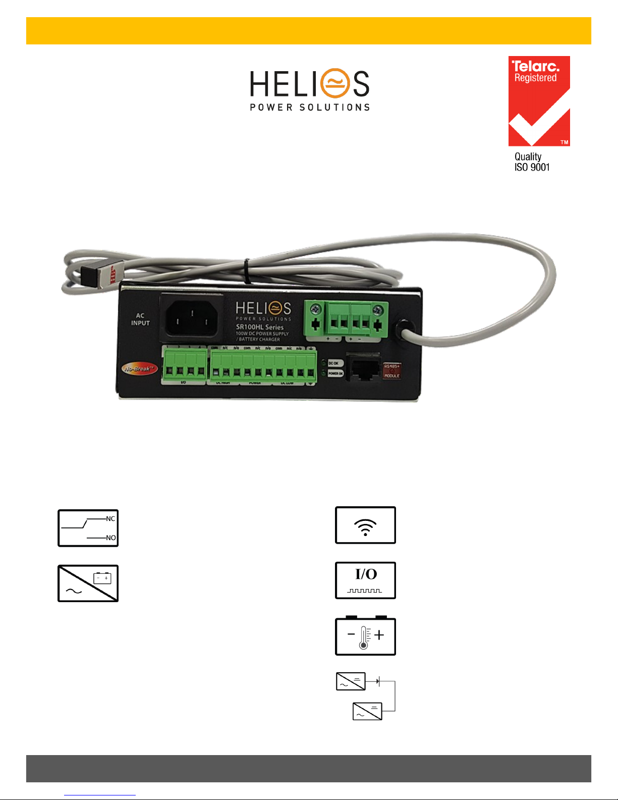
SR100HL Power Supply/ Float Charger for Lead Acid Baeries
OPTIONAL FEATURES
STANDARD FEATURES
3 Relay Alarms-Form C
Float Charger –Lead Acid Baeries
Temperature Sensor on 1.7m lead with adhesive
pad: -4mV / °C /cell ±10%
Comms:
RS232
RS485
Modbus
SNMP & Webpages
Customizable Digital I/O
QUALITY POWER SOLUTIONS BACKED UP BY REAL-WORLD ENGINEERING EXPERIENCE
N+1 Redundancy

2
www.heliosps.com

3
www.heliosps.com
QUALITY POWER SOLUTIONS BACKED UP BY REAL-WORLD ENGINEERING EXPERIENCE
Table of Contents
1. SAFETY ……………………………………………………………………………………………………………………………………………………………...4
2. INTRODUCTION ………………………………………………………………………………………………………………………………………………… 5
3. FRONT PANEL LAYOUT ……………………………..……………………………………………………………………………………………………….5
4. FG - Frame Ground ……………………………………………………………………………………………………………………………….….……….5
5. N+1 REDUNDANCY …………………………………………………………………………………………………………………………………………...6
6. CONNECTION NOTES …………………….………………………………………………………………………………………………………………….6
7. TECHNICAL SPECIFICATIONS .……………….……………………………………………………………………………………….….………………7
8. PHYSICAL ……………………..……………………………………………………………………………………………………...……………….………...8
9. STANDARDS ……………………………..………………………………………………………………………………………………………………....….8
10. CUSTOMISED MODELS ……………………………………………………………………………………………………...………………..………...8
11. TERMS OF WARRANTY ……………………………………………………………………………………………………………………………....….8

4
www.heliosps.com
SR100HL Series - 100 W Power Supply/Float Charger for Lead Acid Baeries
The user is responsible for ensuring that input and output wiring segregation complies with local standards and that in the use of the equipment,
access is confined to operators and service personnel. A low resistance earth connection is essential to ensure safety and additionally, satisfactory
EMI suppression (see below).
HAZARDOUS VOLTAGES EXIST WITHIN A POWER SUPPLY ENCLOSURE AND ANY REPAIRS MUST BE CARRIED OUT BY A
QUALIFIED SERVICEPERSON.
Electrical Strength Tests
Components within the power supply responsible for providing the safety barrier between input and output are constructed to provide electrical
isolation as required by the relevant standard. However EMI filtering components could be damaged as result of excessively long high voltage tests
between input, output and ground. Please contact our technicians for advice regarding electric strength tests.
Earth Leakage
Where fitted, EMC suppression circuits cause earth leakage currents which may be to a maximum of 3.5mA.
Ventilation
High operating temperature is a major cause of power supply failures, for example, a 10oC rise in the operating temperature of a component will
halve its expected life. Therefore always ensure that there is adequate ventilation for the equipment. Batteries in particular suffer shortened
lifetimes if subjected to high ambient temperatures.
Water / Dust
Every effort must be made in the installation to minimise the risk of ingress of water or dust. Water will almost always cause instant failure. The
effects of dust are slower in causing failure of electronic equipment but all electrical equipment should be cleaned free of any dust accumulation at
regular intervals.
Electromagnetic Interference (EMI)
Switching power supplies and converters inherently generate electrical noise. All wiring should be as short as practicable and segregated from all
equipment wiring which is sensitive to EMI. Residual noise can be reduced by looping DC wiring through ferrite cores (sleeves). These are most
effective as close to the power supply as possible and as many turns of the wire taken through the core (+ and - in the same direction) as the core
will accommodate.
External fuse protection
Fuses or circuit breakers must be used in all battery circuits to protect against short circuits. External fuses should be used for power supplies/
chargers even though they are usually internally protected.
Connection polarity
It is critical to check the polarity carefully when connecting DC devices even with models which have non-destructive reverse polarity protection.
1. SAFETY
Glossary of terms used in our user manuals
PSU = power supply unit BCT = baery condion test ECB = electronic circuit breaker
ELVD = electronic low voltage disconnect RPP = reverse polarity protecon EMI = electromagnec interference
SNMP = Simple Network Management
Protocol EMC = Electromagnec compability DOD = depth of discharge

5
www.heliosps.com
SR100HL Series - 100 W Power Supply/Float Charger for Lead Acid Baeries
3. FRONT PANEL LAYOUT
1. AC INPUT IEC60320 - C13 10A
2. DIGITAL INPUT & 1 DIGITAL OUTPUT: I/O terminals are customizable and if used, the product will have a unique code.
3. ALARMS RELAY FORM C: Relay contacts shown in de-energised state(ie. When there is a fault condion). Alarm relays are ener-
gised when power supply is operang normally, eg. “Power” alarm relay is energised when input voltage present.
DC High : DC Output High
POWER: Loss of mains input power. This alarm has 30 seconds delay before acvaon upon mains failure. PSU fails
DC Low: DC Output Low or Baery voltage low if used as a charger.
4. DC CONNECTIONS
5. LED indicaons Code: Mimics alarm condions above
6. COOMS PORT
RS232 (ASCII)
RS485 (ASCII)
Modbus Serial
SNMP, Webpages
7. TEMPCO SENSOR (OPTIONAL): Temperature sensor for voltage compensaon
4. FG - Frame Ground
This terminal provides a connecon to the metal case for earthing.
1
23
4
5
6
7
2. INTRODUCTION:
The SR100HL range is designed for use as a reliable and stable AC to DC power supply, or oat charger for lead acid baer-
ies. Note that for oat charging the output voltage must be set to approximately 15% above the nominal baery voltage
models. This is done as the default voltage for the 12V model but must be specied at me of order for all higher voltage
models.

6
www.heliosps.com
SR100HL Series - 100 W Power Supply/Float Charger for Lead Acid Baeries
5. N+1 REDUNDANCY
Two or more SRxxx series power supplies may be connected in parallel for increased power (with or without diodes). It is essenal
that the wiring from each unit to the load is kept idencal for equal power sharing parcularly when diodes are not used.
6. CONNECTION NOTES
Two outputs connected in parallel internally are provided.
If used as a baery charger ensure that the baery polarity matches the power supply output.
Alarms can be tested by using an external variable voltage supply.
7
www.heliosps.com
SR100HL Series - 100 W Power Supply/Float Charger for Lead Acid Baeries
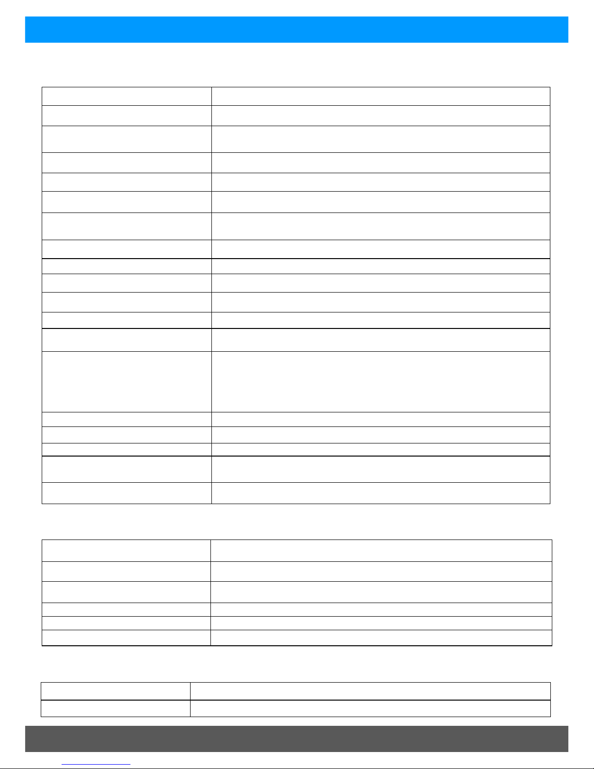
7. TECHNICAL SPECIFICATIONS
Output power 100W (0-50°C )
Input Voltage 180V - 264VAC 45-65Hz
Output Voltages 13.8V, 24, 30V, 36V, 48 VDC
Other voltages by request
Voltage Adj. Range 85% - 105% of Vout
Frequency 45-65Hz
Overcurrent protecon Constant current limit under overload and short circuit condions
Isolaon Input – earth – 2.5KVdc
Output – earth - 500Vdc
Eciency > 85%
Inrush Current < 30A , 1.8ms
Operang temperature -20 to 50 °C ambient at full load
Humidity 0 - 95% relave humidity non - condensing
Cooling Natural convecon
LED Indicaon Green: DC OK
Green: Power OK
Alarms Relay
Form C contacts changeover, rated 30VDC,2A/110VDC,0.3A/125VAC,0.5A
DC Hight ()
POWER (main fails, PSU fail)
DC Low ()
Line Regulaon <0.04% over input range
Load Regulaon <0.5% open circuit to 100% load
Noise <0.3%
Transient response 200mV over/undershoot,
Load step 20-100%, 400us seling me
Hold-up me 15-20 ms (nom-max. Vin) without baery
AC input connector IEC60320— C13 10A input socket (similar to PCs etc)
DC Connecons Plug-in style socket & mang screw terminal block: (max. wire 2.5mm² / way)
Alarm connecons Plug in screw terminal block
Enclosure Zinc plated & powder coated steel
Dimensions 147W x 177D x 62H (±mm)
Weight 0.95 Kg
EMC To CISPR 22 / EN55022 class A
Safety To IEC950 / EN60950 / AS/NZS3260
9. STANDARDS
8. PHYSICAL

8
www.heliosps.com
SR100HL Series - 100 W Power Supply/Float Charger for Lead Acid Baeries
10. CUSTOMISED MODELS
Model code BASE MODEL SPECIAL FEATURES
Helios Power Soluons warrants this product for 24 months from date of shipment against material and workmanship defects. Liabil-
ity under this warranty is limited to the replacement or repair of the defecve product as long as the product has not been damaged
through misapplicaon, negligence, or unauthorized modicaon or repair.
11. TERMS OF WARRANTY
Table of contents
Other Helios Power Supply manuals

Helios
Helios SD Series User manual

Helios
Helios SR250HL User manual

Helios
Helios KWL-KS WE User manual

Helios
Helios SR250A User manual

Helios
Helios SR100A User manual

Helios
Helios ICT Platinum Series User manual

Helios
Helios SR500L Series User manual

Helios
Helios KWL 45 SNU User manual

Helios
Helios HPS-PS-STANDALONE-SR100HL User manual

Helios
Helios Salicru EMi3 User manual


 user manual")


