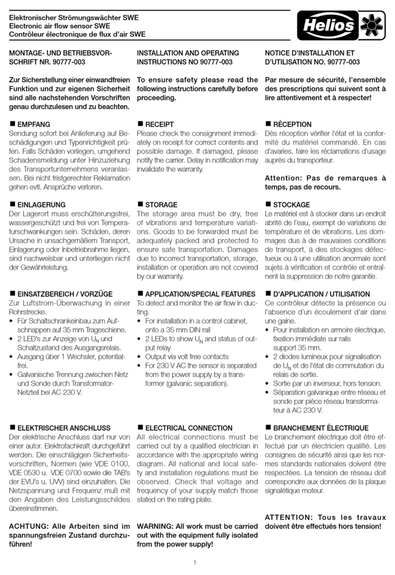
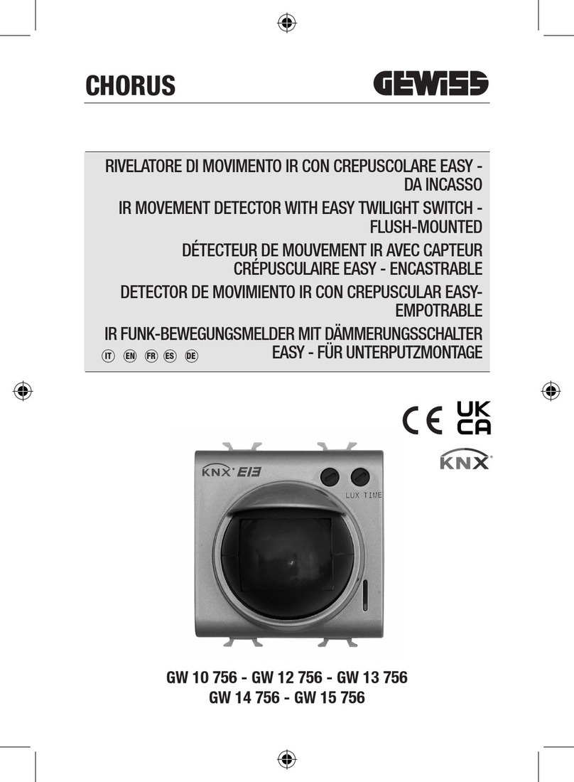
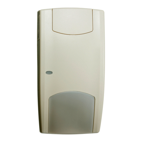
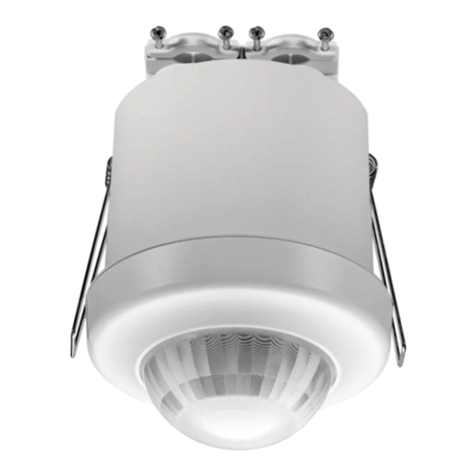
Helios BWM User manual

Helios Ventilatoren
MONTAGE- UND BETRIEBSVORSCHRIFT
INSTALLATION AND OPERATING INSTRUCTIONS
NOTICE DE MONTAGE ET D´UTILISATION
Bewegungsmelder
Motion Detector
Détecteur de mouvement
BWM
zur Erfassung der Anwesenheit von Personen im Raum
for detecting the presence of persons in a room
pour détecter la présence de personnes dans la pièce
FR
EN
DE

DE
1.0 Wichtige Informationen
Zur Sicherstellung einer einwandfreien Funktion und zur eigenen Sicherheit sind alle
nachstehenden Vorschriften genau durchzulesen und zu beachten. Nationale einschlägi-
ge Normen, Sicherheitsbestimmungen und Vorschriften (z.B. DIN EN VDE 0100) sowie
die technischen Anschlussbedingungen des Energieversorgungsunternehmens sind
unbedingt zu beachten und anzuwenden.
Die Bedienungsanleitung als Referenz aufbewahren. Nach der Endmontage muss dem
Betreiber (Mieter/Eigentümer) das Dokument ausgehändigt werden.
1.1 Warn- und Sicherheitshinweise
Nebenstehendes Symbol ist ein sicherheitstechnischer Warnhinweis. Alle
Sicherheitsvorschriften bzw. Symbole müssen unbedingt beachtet werden, damit
jegliche Gefahrensituation vermieden wird.
1.2 Garantieansprüche – Haftungsausschluss
Wenn die nachfolgenden Ausführungen nicht beachtet werden, entfällt unsere
Gewährleistung. Gleiches gilt für Haftungsansprüche an den Hersteller. Der Gebrauch
von Zubehörteilen, die nicht von Helios empfohlen oder angeboten werden, ist nicht
statthaft. Eventuell auftretende Schäden unterliegen nicht der Gewährleistung.
1.3 Vorschriften – Richtlinien
Bei ordnungsgemäßer Installation und bestimmungsgemäßem Betrieb entspricht das
Produkt den zum Zeitpunkt seiner Herstellung gültigen Vorschriften und EG-Richtlinien.
1.4 Sendungsannahme
Die Sendung ist sofort bei Anlieferung auf Beschädigungen und Typenrichtigkeit zu
prüfen. Falls Schäden vorliegen umgehend Schadensmeldung unter Hinzuziehung des
Transportunternehmens veranlassen. Bei nicht fristgerechter Reklamation gehen evtl.
Ansprüche verloren.
1.5 Einlagerung
Bei Einlagerung über einen längeren Zeitraum sind zur Verhinderung schädlicher
Einwirkungen folgende Maßnahmen zu treffen: Schutz durch trockene, luft- und staub-
dichte Verpackung (Kunststoffbeutel mit Trockenmittel und Feuchtigkeitsindikatoren).
Der Lagerort muss erschütterungsfrei, wassergeschützt und frei von übermäßi-
gen Temperaturschwankungen sein. Schäden, deren Ursprung in unsachgemäßem
Transport, unsachgemäßer Einlagerung oder Inbetriebnahme liegen, sind nachweisbar
und unterliegen nicht der Gewährleistung.
1.6 Personalqualifikation
Die Elektroanschlüsse und Inbetriebnahme sowie Installationsarbeiten dürfen nur von
autorisierten Elektrofachkräften ausgeführt werden.
1.7 Einsatzbereich
Der Bewegungsmelder BWM erfasst Bewegungen und die Anwesenheit von Personen
über einen Sensor. Der Bewegungsmelder wird zur bedarfsgerechten Regelung von
Beleuchtung in der Gebäudeautomation, in Fluren, an Arbeitsstätten, in Industriehallen,
in Büros und in Geschäftsräumen eingesetzt.
Der Bewegungsmelder darf nicht für Überwachungszwecke, welche dem Schutz
von Personen gegen Gefährdung oder Verletzung dienen und nicht als Not-Aus-
Schalter an Anlagen und Maschinen oder vergleichbare sicherheitsrelevante Auf-
gaben verwendet werden.
Ein bestimmungsfremder Einsatz ist nicht zulässig!
KAPITEL 1
ALLGEMEINE
HINWEISE
m
Bewegungsmelder – BWM
Montage- und Betriebsvorschrift
1

DE
1.8 Funktion
Der Bewegungsmelder dient zur Erfassung der Bewegung von Personen im Abstand von
bis zu 10 m. Der Sensor erfasst Bewegungen mit einem Öffnungswinkel von 110°
und 360° Umfang. Durch das Linsensystem mit 20 Einzellinsen entstehen sehr klei-
ne Dunkelbereiche, die auch bei einer Entfernung von 10 m nur wenige Zentimeter
groß sind und auch kleinere Bewegungen sicher erfassen.
Der Temperaturunterschied zwischen der zu erfassenden Person und der Umgebung
muss größer als 5 K sein. Der Sensor erkennt Veränderungen der Infrarot-Strahlung
(Wärmestrahlung), die sich aufgrund von Bewegungen von Personen oder
Objekten ergibt. Diese erzeugen eine zeitliche Veränderung des
Temperaturgradienten im Feld. Wird eine Bewegung detektiert, wird der potentialfreie
Relaisausgang geschalten. Die Haltezeit des Ausgangs, gemessen vom Zeitpunkt der
letzten detektierten Bewegung, kann über ein Potentiometer von 4 Sekunden bis ca.
16 Minuten eingestellt werden. Der potentialfreie Wechsler dient nur zum Schalten von
Sicherheitskleinspannungen.
2.0 Technische Daten
BWM
Spannungsversorgung 15 … 36 V DC (±10 %); 24 V AC (±20 %)
Leistungsaufnahme < 1 W bei 24 V DC; < 2 VA bei 24 V AC
Sensor Infrarot-Bewegungssensor
Ausgang Bewegungsmelder potentialfreier Wechsler 24 V / 1 A
Nachlaufzeit einstellbar von 4 Sekunden bis 16 Minuten
Umgebungstemperatur 0 … +50 °C
Elektrischer Anschluss 0,14 – 1,5 mm², über Schraubklemmen auf Platine
Gehäuse Kunststoff, Werkstoff ABS, Farbe Reinweiß (ähnlich RAL
9010)
Kabelverschraubung M16 x 1,5 mit Zugentlastung, auswechselbar,
max. Innendurchmesser 10,4 mm
Schutzklasse lll (nach EN 60 730)
Schutzart IP30 (nach EN 60 529)
Normen CE-Konformität, elektromagnetische Verträglichkeit
nach EN 61326, EMV-Richtlinie 2004/108/EC
Abb.1
Prinzip
Sensor erkennt die Temperaturdifferenz, die sich
aufgrund von Bewegung von Personen oder Ob-
jekten ergibt.
Bewegungssensor
Bewegung
infrarote
Strahlung
infrarote
Strahlung
Temperatur-
differenz
Öffnungswinkel
Sensor mit erweitertem Öffnungswinkel von 100° bzw. 110° so-
wie 360° Umfang und 10m Reichweite.
10m
5m
5m
10m
10m
5m
5m
10m
55°
55° 46,5°
46,5°
X Y
0° 0°
Draufsicht Seitenansicht
Erfassungsbereich
KAPITEL 2
TECHNISCHE
DATEN
Bewegungsmelder – BWM
Montage- und Betriebsvorschrift
2

3.0 Montage
Zur Wandmontage oder zur Montage auf eine Unterputz-Dose (Ø 55 mm) geeignet.
– Wandmontage (Aufputz)
Unterteil (4-Loch) für senkrechte oder waagrechte Montage mit Sollbruchstelle für
Kabeleinführung oben oder unten.
– Montage auf Unterputz-Dose
Unterteil (4-Loch) für Befestigung auf senkrecht oder waagrecht installierten Unterputz-
Dosen mit Kabeleinführung hinten.
3.1 Gehäuse öffnen
Schnapphaken nach innen drücken (s. Abb. 3).
Im Deckel des Gehäuses befindet sich die Elektronik des Geräts.
KAPITEL 3
MONTAGE
85
27
Abb.2
Abb.3
Bewegungsmelder – BWM
Montage- und Betriebsvorschrift
3
DE

Bewegungsmelder – BWM
Montage- und Betriebsvorschrift
4.0 Elektrischer Anschluss
m Der Anschluss desGerätsdarf nur an Sicherheitskleinspannung und im span-
nungslosen Zustand erfolgen. Um Schäden und Fehler am Gerät (z.B. durch
Spannungsinduktion) zu verhindern, sind abgeschirmte Leitungen zu verwenden,
eine Parallelverlegung zu stromführenden Leitungen zu vermeiden und die EMV-
Richtlinien zu beachten.
KAPITEL 4
ELEKTRISCHER
ANSCHLUSS
85499 207 SS-1388 24.06.2020
1
2
3
BWM
D E F
13 11 12
UB+
UB-
24 V AC/DC
Potentiometer
Nachlaufzeit
24 V / 1 A (ohmische Last)
Bewegungsmeldung
24 V / 1 A (ohmic load)
Motion detection
24 V / 1 A (charge ohmique)
Détection de mouvement
Potentiometer
run-on time
Temps de marche
du potentiomètre
4 s - 16 min
Abb.4
4
DE

EN
1.0 Important information
In order to ensure complete and effective operation and for your own safety, all of the
following instructions should be read carefully and observed. The relevant national stan-
dards, safety regulations and instructions (e.g. DIN EN VDE 0100) as well as the technical
connection conditions of the energy supply company must be observed and applied.
Please keep the installation and operating instructions for reference. The document must
be issued to the operator (tenant/owner) after the final assembly.
1.1 Warning and safety instructions
The adjacent symbol is a safety-relevant warning symbol. All safety regulations
and/or symbols must be absolutely adhered to, so that any dangerous situation
is avoided.
1.2 Warranty claims – Exclusion of liability
Our warranty shall not apply if the following instructions are not observed. The same
applies for liability claims against the manufacturer. The use of accessories, which are
not recommended or offered by Helios, is not permitted. Any damage that may occur is
not liable for warranty.
1.3 Regulations - Guidelines
If the product is installed correctly and used to its intended purpose, it conforms to all
applicable regulations and EC guidelines at its date of manufacture.
1.4 Receipt
Please check delivery immediately on receipt for accuracy and damage. If damaged,
please notify the carrier immediately. In case of delayed notification, any possible claim
may be void.
1.5 Storage
When storing for a prolonged time, the following steps are to be taken to avoid damaging
influences: Protection by dry, air-dustproof packing (plastic bags with drying agent and
moisture indicators). The storage place must be waterproof, vibration-free and free of
excessive temperature variations. Damages due to improper transportation, storage or
commissioning must be verified and are not liable for warranty.
1.6 Personnel qualification
The electrical connection and commissioning as well as the installation work must only
be carried out by qualified electricians.
1.7 Area of application
The motion detector BWM detects movements and the presence of persons via a sen-
sor. The motion sensor is used for the demand-based regulation of lighting in building
automation, in corridors, in workplaces, in industrial buildings, in offices and in business
premises.
The motion detector must not be used for monitoring purposes which serve to protect
persons against hazards or injury and it must not be used as an emergency stop
switch for systems and machines or comparable safety-related tasks.
Any use other than the intended use is prohibited!
CHAPTER 1
GENERAL
INFORMATION
m
Motion Detector – BWM
Installation and Operating Instructions
1

EN
1.8 Function
The motion detector is used to detect the movement of persons at a distance of up to
10 m. The sensor detects movements with an opening angle of 110° and 360° sco-
pe. The lens system with 20 individual lenses results in very small dark areas, which
are only a few centimetres in size at a distance of 10 m and safely detect smaller
movements.
The temperature difference between the person to be detected and the environment
must be greater than 5 K. The sensor detects changes in the infrared radiation (ther-
mal radiation)resulting from the movement of persons or objects. These generate a
temporal change in the temperature gradients in the field. If a movement is detected,
the potential-free relay output is switched. The hold time for the output, measured from
the time of the last detected movement, can be set from 4 seconds to around 16 minu-
tes via potentiometer. The potential-free changeover contact is only used for switching
safety extra-low voltages.
2.0 Technical data
BWM
Power supply 15 … 36 V DC (±10 %); 24 V AC (±20 %)
Power consumption < 1 W at 24 V DC; < 2 VA at 24 V AC
Sensor Infrared motion sensor
Motion detector output Potential-free changeover contact 24 V / 1 A
Overrun timer Adjustable from 4 seconds to 16 minutes
Ambient temperature 0 … +50 °C
Electrical connection 0.14 – 1.5 mm², via screw terminals on board
Casing Plastic, material ABS, colour pure white (similar to RAL
9010)
Cable gland M16 x 1.5 with strain relief, replaceable,
max. internal diameter 10.4 mm
Protection class lll (according to EN 60 730)
Protection category IP30 (according to EN 60 529)
Standards CE conformity, electromagnetic compatibility
according to EN 61326, EMC guideline 2004/108/EC
Fig.1
Principle
Sensor detects the temperature difference resul-
ting from the movement of persons or objects.
Bewegungssensor
Bewegung
infrarote
Strahlung
infrarote
Strahlung
Temperatur-
differenz
Opening angle
Sensor with extended opening angle of 100° or 110° and 360°
scope and 10m range.
10m
5m
5m
10m
10m
5m
5m
10m
55°
55° 46,5°
46,5°
X Y
0° 0°
Draufsicht Seitenansicht
Detection zone
CHAPTER 2
TECHNICAL DATA
Motion Detector – BWM
Installation and Operating Instructions
2
Infrared
radiation
Infrared
radiation
Motion detector
Temperature
difference
Movement
Top view Side view

3.0 Installation
Suitable for wall installation or installation on a flush-mounted box (Ø 55 mm).
– Wall installation (surface-mounted)
Base (4 hole) for vertical or horizontal installation with predetermined breaking point for
cable entry at top or bottom.
– Installation on flush-mounted box
Base (4 hole) for attachment to vertically or horizontally installed flush-mounted box
with cable entry at the back.
3.1 Open casing
Push snap-in hooks inwards (see Fig. 3).
The unit electronics are located in the casing cover.
CHAPTER 3
INSTALLATION
85
27
Fig.2
Fig.3
Motion Detector – BWM
Installation and Operating Instructions
3
EN

Motion Detector – BWM
Installation and Operating Instructions
4.0 Electrical connection
m The unit may only be connected to safety extra-low voltage and under dead-vol-
tage condition. In order to prevent damage and unit errors (e.g. due to voltage induc-
tion), shielded cables must be used, avoid laying parallel to current-carrying cables
and observe EMC guidelines.
CHAPTER 4
ELECTRICAL
CONNECTION
85499 207 SS-1388 24.06.2020
1
2
3
BWM
D E F
13 11 12
UB+
UB-
24 V AC/DC
Potentiometer
Nachlaufzeit
24 V / 1 A (ohmische Last)
Bewegungsmeldung
24 V / 1 A (ohmic load)
Motion detection
24 V / 1 A (charge ohmique)
Détection de mouvement
Potentiometer
run-on time
Temps de marche
du potentiomètre
4 s - 16 min
Fig.4
4
EN

FR
1.0 Informations importantes
Il est important de bien lire et suivre l’ensemble des consignes suivantes pour le bon
fonctionnement de l’appareil et pour la sécurité des utilisateurs. Les normes nationales,
les conditions de sécurité et les réglementations (C 15.100 par exemple) ainsi que les
conditions techniques de raccordement de la société d’approvisionnement en électricité
sont à respecter et à appliquer impérativement. Conserver la notice de montage et d’uti-
lisation comme référence à proximité de l’appareil. Après le montage final, le document
doit être remis à l’utilisateur (locataire/propriétaire).
1.1 Consignes de sécurité
Les symboles ci-contre indiquent une consigne de sécurité. Toutes les consignes
de sécurité ainsi que les symboles doivent être impérativement respectés, afin
d’éviter tout danger.
1.2 Garantie – Réserves du constructeur
Si toutes les consignes indiquées dans cette notice ne sont pas correctement res-
pectées, la garantie s’annule. Idem pour les garanties constructeur Helios. L’utilisation
d’accessoires, non fournis, non conseillés ou non proposés par Helios, est interdite.
Tous changements ou transformations effectués sur l’appareil sont interdits, altèrent sa
conformité et annulent la garantie.
1.3 Normes - Règlementations
Cet appareil est conforme aux directives CE en vigueur le jour de sa fabrication et sous
d’une réserve d’une utilisation appropriée.
1.4 Réception de la marchandise
Dès réception, vérifier l‘état et la conformité du matériel commandé. En cas de dégâts,
les signaler immédiatement en mentionnant le nom du transporteur. Attention, le non-re-
spect de ces procédures peut entraîner le rejet de la réclamation.
1.5 Stockage
Pour un stockage de longue durée et pour éviter toute détérioration préjudiciable, il con-
vient de se conformer aux instructions suivantes : protéger avec un emballage sec, étan-
che à l’air et à la poussière (sac en matière synthétique contenant des sachets déshyd-
rateurs et un indicateur d’humidité). stocker le matériel dans un endroit abrité de l’eau,
exempt de vibrations et de variations de températures excessives. Les dégâts dus à un
transport non conforme, un stockage inadéquat ou une mauvaise installation ne sont
pas couverts par la garantie.
1.6 Qualification du personnel
Les raccordements électriques et les mises en service électroniques ne doivent être
effectués que par des électriciens qualifiés.
1.7 Domaines d‘utilisation
Le détecteur de mouvements BWM détecte les mouvements et la présence de person-
nes via un capteur. Le détecteur de mouvements est utilisé pour contrôler l‘éclairage
dans les bâtiments, les couloirs, sur les lieux de travail, dans les halls industriels, les
bureaux et les locaux commerciaux.
Le détecteur de mouvements ne doit pas être utilisé à des fins de surveillance ser-
vant à protéger les personnes contre les dangers ou les blessures et ne doit pas
être utilisé comme interrupteur d‘arrêt d‘urgence sur des systèmes et des machines
ou pour des tâches comparables concernant la sécurité.
Tout usage inapproprié n’est pas autorisé !
CHAPITRE 1
INFORMATIONS
GÉNÉRALES
m
Détecteur de mouvements – BWM
Notice de montage et d‘utilisation
1

FR
1.8 Fonctionnement
Le détecteur de mouvements est utilisé pour détecter les mouvements des personnes
à une distance allant jusqu‘à 10 m. Le capteur détecte les mouvements avec un
angle d‘ouverture de 110° sur 360°. Le système de lentilles composé de 20 lentilles
individuelles ne laisse que de très petites zones sombres, qui ne font que quelques
centimètres même à une distance de 10 m et détectent donc les petits mouvements
de manière fiable.
La différence de température entre la personne à détecter et l‘environnement doit être
supérieure à 5 K. Le capteur détecte les mouvements des personnes ou des objets
dans le rayonnement infrarouge (rayonnement thermique). Ceux-ci génèrent un ch-
angement du gradient de température dans le champ. Si un mouvement est détecté,
la sortie de relais est commutée. Le temps de maintien de la sortie, mesuré à partir
du dernier mouvement détecté, peut être réglé par un potentiomètre de 4 secondes à
environ 16 minutes. Le contact inverseur n‘est utilisé que pour la commutation de très
basses tensions de sécurité.
2.0 Données techniques
BWM
Alimentation 15 … 36 V DC (±10 %); 24 V AC (±20 %)
Consommation d‘énergie < 1 W à 24 V DC; < 2 VA à 24 V AC
Capteur Détecteur de mouvement infrarouge
Sortie du détecteur Contact inverseur 24 V / 1 A
Temps de maintien Réglable de 4 secondes à 16 minutes
Plage de température 0 … +50 °C
Raccordement électrique 0,14 – 1,5 mm², via des bornes sur le circuit imprimé
Boîtier Plastique, matériau ABS, blanc (similaire au RAL
9010)
Presse-étoupe M16 x 1,5 avec décharge de traction, interchangeable,
diamètre intérieur max. 10,4 mm
Classe de protection lll (selon EN 60 730)
Protection IP30 (selon EN 60 529)
Normes Conformité CE, compatibilité électromagnétique selon la
norme EN 61326, directive CEM 2004/108/CE
CHAPITRE 2
DONNÉES
TECHNIQUES
Détecteur de mouvements – BWM
Notice de montage et d‘utilisation
2
Fig. 1
Principe
Le capteur détecte la différence de température
résultant du mouvement des personnes ou des
objets.
Bewegungssensor
Bewegung
infrarote
Strahlung
infrarote
Strahlung
Temperatur-
differenz
Angle
Capteur avec un angle de 100° ou 110° et 360° et une portée
de 10 m.
10m
5m
5m
10m
10m
5m
5m
10m
55°
55° 46,5°
46,5°
X Y
0° 0°
Draufsicht Seitenansicht
Zone de détection

3.0 Montage
Convient pour un montage mural ou pour un montage en boîte d‘encastrement (Ø 55 mm)
– Montage mural (apparent)
Partie inférieure (4 trous) pour montage vertical ou horizontal avec pré-découpe pour
l‘entrée du câble en haut ou en bas.
– Montage en boîte d‘encastrement
Partie inférieure (4 trous) pour le montage en boîtes d‘encastrement installées vertica-
lement ou horizontalement avec entrée de câble à l‘arrière.
3.1 Ouverture du boîtier
Appuyer sur le taquets vers l‘intérieur (voir fig. 3).
Le couvercle du boîtier contient l‘électronique de l‘appareil.
CHAPITRE 3
MONTAGE
85
27
Fig.2
Fig. 3
Détecteur de mouvements – BWM
Notice de montage et d‘utilisation
3
FR

Détecteur de mouvements – BWM
Notice de montage et d‘utilisation
4.0 Raccordement électrique
m L‘appareil ne doit être raccordé qu‘à une très basse tension de sécurité et l‘opé-
ration doit être effectuée hors tension. Afin d‘éviter des dommages et des erreurs
sur l‘appareil (par exemple en raison de l‘induction de tension), des câbles blindés
doivent être utilisés, la pose à proximité de câbles sous tension doit être évitée et les
directives CEM doivent être respectées.
CHAPITRE 4
RACCORDEMENT
ÉLECTRIQUE
4
FR
85499 207 SS-1388 24.06.2020
1
2
3
BWM
D E F
13 11 12
UB+
UB-
24 V AC/DC
Potentiometer
Nachlaufzeit
24 V / 1 A (ohmische Last)
Bewegungsmeldung
24 V / 1 A (ohmic load)
Motion detection
24 V / 1 A (charge ohmique)
Détection de mouvement
Potentiometer
run-on time
Temps de marche
du potentiomètre
4 s - 16 min
Fig. 4

Détecteur de mouvements – BWM
Notice de montage et d‘utilisation
FR
5

Détecteur de mouvements – BWM
Notice de montage et d‘utilisation
FR
6

Service und Information
DHELIOS Ventilatoren GmbH + Co KG · Lupfenstraße 8 · 78056 VS-Schwenningen FHELIOS Ventilateurs · Le Carré des Aviateurs · 157 avenue Charles Floquet · 93155 Le Blanc Mesnil Cedex
CH HELIOS Ventilatoren AG · Tannstraße 4 · 8112 Otelfingen GB HELIOS Ventilation Systems Ltd. · 5 Crown Gate · Wyncolls Road · Severalls Industrial Park ·
AHELIOS Ventilatoren · Postfach 854 · Siemensstraße 15 · 6023 Innsbruck Colchester · Essex · CO4 9HZ
www.heliosventilatoren.de
Als Referenz am Gerät griffbereit aufbewahren! Druckschrift-Nr.
Please keep this manual for reference with the unit!Print no.
Conservez cette notice à proximité de l´apareil! NoRéf. 25 043-001/20-0194/V01/0920
Table of contents
Languages:
Other Helios Security Sensor manuals
