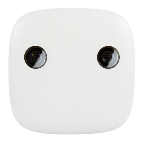
HELLA Aglaia APS-90-Lite User manual

HAGL-120-00077
Version 1.0
Assembly Instructions
APS-90-Lite
ADVANCED PEOPLE
SENSOR
Original Assembly Instructions

2 / 36
The reproduction, distribution and utilization of this document as well as the communication of its contents
to others without express authorization is prohibited. Offenders will be held liable for the payment of damages.
All rights reserved in the event of the grant of patent, utility model or design.
02.06.2022
Version 1.0
HELLA Aglaia Mobile Vision GmbH, Berlin
HELLA Aglaia Mobile Vision GmbH
Ullsteinstraße 140
12109 Berlin
Germany
Telephone: +49 30 2000429-0
Fax: +49 30 2000429-109
E-mail: [email protected]
Internet: www.people-sensing.com
©2022

3 / 36
The reproduction, distribution and utilization of this document as well as the communication of its contents
to others without express authorization is prohibited. Offenders will be held liable for the payment of damages.
All rights reserved in the event of the grant of patent, utility model or design.
02.06.2022
Version 1.0
Supplemental Directives
APS-90-Lite
SUPPLEMENTAL DIRECTIVES
C
Copyrigh
t
t Information
© 2022 HELLA Aglaia Mobile Vision GmbH. All rights reserved. This manual is protected by copyright. It may not be
reproduced in whole or in part or transmitted in any form, electronic or mechanical, including photocopying and recording,
without the prior written permission of HELLA Aglaia Mobile Vision GmbH. Violations are subject to the criminal provisions
of copyright law.
HELLA Aglaia Mobile Vision GmbH reserves the right to revise or replace this manual at any time and without prior notice.
Make sure that you have the appropriate version of this manual for the installed firmware version of the device. If you have
any questions, please contact HELLA Aglaia Mobile Vision GmbH.
HELLA Aglaia Mobile Vision GmbH does not guarantee the completeness, accuracy, or timeliness of the laws, guidelines,
or regulations referred to or quoted, whether directly or indirectly, in this manual. It is the responsibility of the user to
become familiar with the current laws, guidelines, and regulations that apply to their work.
HELLA Aglaia Mobile Vision GmbH reserves the right to modify the described devices (including the respective soware)
without prior notice, irrespective of the content of this manual. Unless expressly agreed upon in writing, HELLA Aglaia
Mobile Vision GmbH is not obligated to notify the owner or user of the devices described in this manual (including the
respective soware) of any revisions, updates, or modifications without further request.
With regard to the APS-90-Lite, HELLA Aglaia Mobile Vision GmbH‘s liability is limited to the terms and conditions of
purchase. The information provided in this manual is not a warranty or guarantee of any kind. Stipulations concerning the
devices described in this manual are only deemed warranties if they are expressly referred to as such in writing and contain
a description of the warranty’s scope and the product covered by the warranty.
The product and company names mentioned in this manual may be protected trademarks of other manufacturers.
The information contained in this manual has been prepared by HELLA Aglaia Mobile Vision GmbH with great care using
sources available to HELLA Aglaia Mobile Vision GmbH. However, HELLA Aglaia Mobile Vision GmbH shall not be respon-
sible for any errors, incorrect or incorrectly compiled data, and any consequences resulting therefrom, irrespective of the
legal basis, provided that HELLA Aglaia Mobile Vision GmbH‘s conduct amounts to no more than ordinary negligence.
The aforementioned exclusion of liability does not apply to damages resulting from injury to life, body, or health or to
damages that are caused intentionally, by gross negligence on the part of HELLA Aglaia Mobile Vision GmbH, or by the
violation of due diligence requirements in connection with the development, manufacture, and distribution of the products
described in this manual.
This does not affect the liability regardless of negligence or fault pursuant to legal regulations such as the Product Liability
Act.

4 / 36
The reproduction, distribution and utilization of this document as well as the communication of its contents
to others without express authorization is prohibited. Offenders will be held liable for the payment of damages.
All rights reserved in the event of the grant of patent, utility model or design.
02.06.2022
Version 1.0
Table of Contents
APS-90-Lite
TABLE OF CONTENTS
1 Overview. . . . . . . . . . . . . . . . . . . . . . . . . . . . . . . . . . . . . . . . . . . . . . . . . . . . . . . 6
2 General Information. . . . . . . . . . . . . . . . . . . . . . . . . . . . . . . . . . . . . . . . . . . . . . 7
2
2.1 Abou
t
t thi
s
s Document
. . . . . . . . . . . . . . . . . . . . . . . . . . . . . . . . . . . . . . . . . . . . . . . . . . . . . . . . . . . . . . . . . . . . . . . . 7
7
2.2 Abou
t
t th
e
e Manufacturer
. . . . . . . . . . . . . . . . . . . . . . . . . . . . . . . . . . . . . . . . . . . . . . . . . . . . . . . . . . . . . . . . . . . . . . 8
8
2.3 Limitatio
n
n o
f
f Liability
. . . . . . . . . . . . . . . . . . . . . . . . . . . . . . . . . . . . . . . . . . . . . . . . . . . . . . . . . . . . . . . . . . . . . . . . 8
8
2.4 Scop
e
e o
f
f Delivery
. . . . . . . . . . . . . . . . . . . . . . . . . . . . . . . . . . . . . . . . . . . . . . . . . . . . . . . . . . . . . . . . . . . . . . . . . . . . 9
9
2.5 Us
e
e o
f
f th
e
e Advance
d
d Peopl
e
e Sensor
. . . . . . . . . . . . . . . . . . . . . . . . . . . . . . . . . . . . . . . . . . . . . . . . . . . . . . . . . . . . 9
9
2.6 Privac
y
y o
f
f Dat
a
a Statement
. . . . . . . . . . . . . . . . . . . . . . . . . . . . . . . . . . . . . . . . . . . . . . . . . . . . . . . . . . . . . . . . . . . . 1
10
3 Hardware. . . . . . . . . . . . . . . . . . . . . . . . . . . . . . . . . . . . . . . . . . . . . . . . . . . . . . 11
3.1 Housing
. . . . . . . . . . . . . . . . . . . . . . . . . . . . . . . . . . . . . . . . . . . . . . . . . . . . . . . . . . . . . . . . . . . . . . . . . . . . . . . . . . . 1
11
3.2 Etherne
t
t Por
t
t o
n
n Device
. . . . . . . . . . . . . . . . . . . . . . . . . . . . . . . . . . . . . . . . . . . . . . . . . . . . . . . . . . . . . . . . . . . . . . 1
11
3.3 I/
O
O Por
t
t o
n
n Device
. . . . . . . . . . . . . . . . . . . . . . . . . . . . . . . . . . . . . . . . . . . . . . . . . . . . . . . . . . . . . . . . . . . . . . . . . . . 1
12
3.4 Statu
s
s LED
. . . . . . . . . . . . . . . . . . . . . . . . . . . . . . . . . . . . . . . . . . . . . . . . . . . . . . . . . . . . . . . . . . . . . . . . . . . . . . . . . 1
12
3.5 Factor
y
y Rese
t
t Button/Pin
. . . . . . . . . . . . . . . . . . . . . . . . . . . . . . . . . . . . . . . . . . . . . . . . . . . . . . . . . . . . . . . . . . . . . 1
13
4 Technical Data. . . . . . . . . . . . . . . . . . . . . . . . . . . . . . . . . . . . . . . . . . . . . . . . . . 14
4.1 Mechanica
l
l Data
. . . . . . . . . . . . . . . . . . . . . . . . . . . . . . . . . . . . . . . . . . . . . . . . . . . . . . . . . . . . . . . . . . . . . . . . . . . . 1
14
4.2 Hardwar
e
e Interfac
e
e Specifications
. . . . . . . . . . . . . . . . . . . . . . . . . . . . . . . . . . . . . . . . . . . . . . . . . . . . . . . . . . . . . 1
14
4.2.1 Ethernet. . . . . . . . . . . . . . . . . . . . . . . . . . . . . . . . . . . . . . . . . . . . . . . . . . . . . . . . . . . . . . . . . . . . . . . . . . . . . . . . . . 14
4.2.2 I/O Port. . . . . . . . . . . . . . . . . . . . . . . . . . . . . . . . . . . . . . . . . . . . . . . . . . . . . . . . . . . . . . . . . . . . . . . . . . . . . . . . . . . 15
4.3 Electrica
l
l Data
. . . . . . . . . . . . . . . . . . . . . . . . . . . . . . . . . . . . . . . . . . . . . . . . . . . . . . . . . . . . . . . . . . . . . . . . . . . . . . 1
16
4.4 Optica
l
l Data
. . . . . . . . . . . . . . . . . . . . . . . . . . . . . . . . . . . . . . . . . . . . . . . . . . . . . . . . . . . . . . . . . . . . . . . . . . . . . . . . 1
17
4.5 Environmenta
l
l Conditions
. . . . . . . . . . . . . . . . . . . . . . . . . . . . . . . . . . . . . . . . . . . . . . . . . . . . . . . . . . . . . . . . . . . . 1
17
4.6 Produc
t
t Labels
. . . . . . . . . . . . . . . . . . . . . . . . . . . . . . . . . . . . . . . . . . . . . . . . . . . . . . . . . . . . . . . . . . . . . . . . . . . . . 1
18
5 Installation. . . . . . . . . . . . . . . . . . . . . . . . . . . . . . . . . . . . . . . . . . . . . . . . . . . . . 19
5.1 Requirements
. . . . . . . . . . . . . . . . . . . . . . . . . . . . . . . . . . . . . . . . . . . . . . . . . . . . . . . . . . . . . . . . . . . . . . . . . . . . . . 1
19
5.2 Wirin
g
g Examples
. . . . . . . . . . . . . . . . . . . . . . . . . . . . . . . . . . . . . . . . . . . . . . . . . . . . . . . . . . . . . . . . . . . . . . . . . . . . 2
21
5.2.1 Power Supply. . . . . . . . . . . . . . . . . . . . . . . . . . . . . . . . . . . . . . . . . . . . . . . . . . . . . . . . . . . . . . . . . . . . . . . . . . . . . 21
5.2.2 Digital Input With an IR-Sensor. . . . . . . . . . . . . . . . . . . . . . . . . . . . . . . . . . . . . . . . . . . . . . . . . . . . . . . . . . . . . . . 21
5.2.3 Digital Output With Potential-Free Contacts. . . . . . . . . . . . . . . . . . . . . . . . . . . . . . . . . . . . . . . . . . . . . . . . . . . . 22

5 / 36
The reproduction, distribution and utilization of this document as well as the communication of its contents
to others without express authorization is prohibited. Offenders will be held liable for the payment of damages.
All rights reserved in the event of the grant of patent, utility model or design.
02.06.2022
Version 1.0
Table of Contents
APS-90-Lite
5.2.4 Digital Output With Buzzer. . . . . . . . . . . . . . . . . . . . . . . . . . . . . . . . . . . . . . . . . . . . . . . . . . . . . . . . . . . . . . . . . . 23
5.2.5 Digital Output With Relay. . . . . . . . . . . . . . . . . . . . . . . . . . . . . . . . . . . . . . . . . . . . . . . . . . . . . . . . . . . . . . . . . . . . 23
5
5.3 Multi Sensor Fusion
. . . . . . . . . . . . . . . . . . . . . . . . . . . . . . . . . . . . . . . . . . . . . . . . . . . . . . . . . . . . . . . . . . . . . . . . . 2
24
6 Cleaning and Maintenance. . . . . . . . . . . . . . . . . . . . . . . . . . . . . . . . . . . . . . . . . . 29
6.1 Cleaning
. . . . . . . . . . . . . . . . . . . . . . . . . . . . . . . . . . . . . . . . . . . . . . . . . . . . . . . . . . . . . . . . . . . . . . . . . . . . . . . . . . . 2
29
6.2 Maintenance
. . . . . . . . . . . . . . . . . . . . . . . . . . . . . . . . . . . . . . . . . . . . . . . . . . . . . . . . . . . . . . . . . . . . . . . . . . . . . . . . 2
29
7 Disposal. . . . . . . . . . . . . . . . . . . . . . . . . . . . . . . . . . . . . . . . . . . . . . . . . . . . . . . 30
8 Appendix. . . . . . . . . . . . . . . . . . . . . . . . . . . . . . . . . . . . . . . . . . . . . . . . . . . . . . . 31
8.1 Ordering Information
. . . . . . . . . . . . . . . . . . . . . . . . . . . . . . . . . . . . . . . . . . . . . . . . . . . . . . . . . . . . . . . . . . . . . . . . 3
31
8.2 Federal Communications Commission (FCC) Statement
. . . . . . . . . . . . . . . . . . . . . . . . . . . . . . . . . . . . . . . . . . . 3
32
9 Glossary and Abbreviations. . . . . . . . . . . . . . . . . . . . . . . . . . . . . . . . . . . . . . . . . 33
10 Index. . . . . . . . . . . . . . . . . . . . . . . . . . . . . . . . . . . . . . . . . . . . . . . . . . . . . . . . . 34

6 / 36
The reproduction, distribution and utilization of this document as well as the communication of its contents
to others without express authorization is prohibited. Offenders will be held liable for the payment of damages.
All rights reserved in the event of the grant of patent, utility model or design.
02.06.2022
Version 1.0
Overview
APS-90-Lite
1 OVERVIEW
The Advanced People Sensor (APS
+
) counts persons within the configured area/moni-
tored area based on stereoscopic imaging and image processing. The counting data is
stored internally and can be transferred via different interfaces for external processing.
Fig. 1: People sensing
1 Advanced People Sensor (APS) 2 Configured area/monitored area
3 Counting line
The results can be verified using video recording (optional). This enables a precise valida-
tion of the counting accuracy.

7 / 36
The reproduction, distribution and utilization of this document as well as the communication of its contents
to others without express authorization is prohibited. Offenders will be held liable for the payment of damages.
All rights reserved in the event of the grant of patent, utility model or design.
02.06.2022
Version 1.0
General Information
APS-90-Lite
2 GENERAL INFORMATION
2.1 About this Document
This manual provides information for optimal configuration and efficient operation of the
device.
Personnel must carefully read and fully understand this manual before performing any
installation or configuration tasks.
The figures in this manual are for information only. Actual design may differ from illustra-
tions.
T
Targe
t
t Group
This document is addressed to system integrators.
Hardwar
e
e Version
All information in this manual refers to hardware APS-90-Lite.
Modifications to the functionality which will be implemented through future hardware
updates will be described in an updated version of the manual.
Notes
Notes and safety instructions are marked by symbols in this manual.
For safety instructions the relevant symbol and words indicate the severity of the danger.
NOTICE
This combination of symbol and signal word indicates a potentially
dangerous situation, which can lead to property damage, data loss or
misuse of the device if not avoided.
This symbol highlights useful tips and recommendations as well as
information for efficient and trouble-free operation.

8 / 36
The reproduction, distribution and utilization of this document as well as the communication of its contents
to others without express authorization is prohibited. Offenders will be held liable for the payment of damages.
All rights reserved in the event of the grant of patent, utility model or design.
02.06.2022
Version 1.0
General Information
APS-90-Lite
S
Symbols
A superscript plus-sign aer a word indicates a glossary entry for
this word. To view the glossary entry click on the plus-sign.
This symbol highlights useful tips and recommendations as well as
information for efficient and trouble-free operation in a paragraph.
2.2 About the Manufacturer
Servic
e
e Requests
Service requests regarding the device can be sent to the following email address:
You can also use our support center at: ໊support.people-sensing.com.
The general contact information is shown on page 2.
Warrant
y
y Information
The warranty information is included in the general terms and conditions of HELLA Aglaia.
2.3 Limitation of Liability
All the data and notes in this manual were compiled considering the applicable standards
and regulations as well as the state of the art.
In the following cases HELLA Aglaia assumes no liability for damages:
ࡇNon-compliance with this manual.
ࡇDeviation from the intended use.
ࡇAssignment of untrained personnel.
ࡇUnauthorized technical changes.
ࡇUse of unauthorized accessories.
ࡇOpening the device.
ࡇDamage or removal of the "DO NOT OPEN DEVICE" label.
ࡇDamage or removal of the seal.
For special models, use of additional order options, or current technical changes, the
actual scope of delivery can deviate from the explanations and illustrations in this manual.
The obligations agreed upon in the delivery contract, General terms and conditions and
delivery conditions of HELLA Aglaia as well as any legal regulations applicable at the time
of the contract conclusion apply.

9 / 36
The reproduction, distribution and utilization of this document as well as the communication of its contents
to others without express authorization is prohibited. Offenders will be held liable for the payment of damages.
All rights reserved in the event of the grant of patent, utility model or design.
02.06.2022
Version 1.0
General Information
APS-90-Lite
2.4 Scope of Delivery
The standard scope of delivery for the device includes:
ࡇThe Advanced People Sensor.
ࡇThis manual as a digital version by download.
ࡇThe configuration manual as a digital version by download.
2.5 Use of the Advanced People Sensor
I
Intende
d
d Use
The Advanced People Sensor is a sensor assembly, which must be integrated into other
systems.
The Advanced People Sensor is intended for automatically counting persons in the config-
ured monitored area.
The Advanced People Sensor is intended for detecting and monitoring persons in the
configured monitored zone or detecting wireless devices in combination with a wireless
USB adapter.
Proper and safe operation of the product requires appropriate transport, storage and
installation as well as attentive operation and care.
The information in this manual must also fully comply with use to be deemed ‘intended’.
Any use which deviates or exceeds the intended use is considered as ‘misuse’.
No
n
n Intende
d
d Use
The following list contains, but is not limited to, the following examples of non intended
use:
ࡇUse as the sole people detector for switching safety relevant equipment e.g. to close a
door.
ࡇUse with unauthorized modified firmware.
ࡇOpening the device or use without housing.
ࡇUse in unsuitable environments (e.g. use outdoors if the Advanced People Sensor is
not specified for outdoor operations).

10 / 36
The reproduction, distribution and utilization of this document as well as the communication of its contents
to others without express authorization is prohibited. Offenders will be held liable for the payment of damages.
All rights reserved in the event of the grant of patent, utility model or design.
02.06.2022
Version 1.0
General Information
APS-90-Lite
2.6 Privacy of Data Statement
It should be noted that the APS
+
can be used as a camera, and that it is possible to record
and store video data. Under certain conditions it may also be possible to identify a person.
The standard scope of delivery shows a static camera view image in the HMI. Therefore,
people are usually not visible.
The user must establish in advance whether there are legal requirements or privacy
regulations applicable when using the people sensor. Appropriate measures should be
taken to prevent unauthorized access to the unit.
It is possible to switch off or permanently disable the video streaming and recording
functions. For more sensitive environments, we do also provide a firmware version where
no people are visualized.
To prevent unauthorized access to the device, change the password for the admin user. Or
better, create new users and delete the existing admin user.
To prevent unauthorized access to the device, you will be prompted to change the pass-
word of the admin user the first time you log in aer the update. Or better, create new
users and delete the existing admin user.

11 / 36
The reproduction, distribution and utilization of this document as well as the communication of its contents
to others without express authorization is prohibited. Offenders will be held liable for the payment of damages.
All rights reserved in the event of the grant of patent, utility model or design.
02.06.2022
Version 1.0
Hardware
APS-90-Lite
Fig. 3: RJ45
Ethernet interface
("A": optics orientation)
3 HARDWARE
3.1 Housing
Fig. 2: Housing
1 Ethernet interface (RJ45), X2 2 Factory reset button
3 Fixing holes 4 Right HDR camera
5 Le HDR camera 6 Status LED
7 I/O interface (Mini-Fit-jr, 2x4), X1
3.2 Ethernet Port on Device
P
Pi
n
n no. Name Description
1 TxRx A + Transmit/Receive A (positive polarity)
2 TxRx A − Transmit/Receive A (negative polarity)
3 TxRx B + Transmit/Receive B (positive polarity)
4 TxRx C + Transmit/Receive C (positive polarity)
5 TxRx C − Transmit/Receive C (negative polarity)
6 TxRx B − Transmit/Receive B (negative polarity)
7 TxRx D + Transmit/Receive D (positive polarity)
8 TxRx D − Transmit/Receive D (negative polarity)

12 / 36
The reproduction, distribution and utilization of this document as well as the communication of its contents
to others without express authorization is prohibited. Offenders will be held liable for the payment of damages.
All rights reserved in the event of the grant of patent, utility model or design.
02.06.2022
Version 1.0
Hardware
APS-90-Lite
Fig. 4: Mini-Fit I/O Interface
("A": optics orientation)
3.3 I/O Port on Device
P
Pi
n
n no. Name Description
1 PWR + DC voltage supply +
(12 ... 30 V)
2 IN1 + Programmable input +, potential-free
(typically used for a door contact)
3 IN2 + Programmable input +, potential-free
(typically used for a door contact)
4 OUT1 + Programmable output +, potential-free
5 GND DC voltage supply -
6 IN1 - Programmable input -, potential-free
(typically used for a door contact)
7 IN2 - Programmable input -, potential-free
(typically used for a door contact)
8 OUT1 - Programmable output -, potential-free
3.4 Status LED
Statu
s
s LED
Starting the device takes about 40 seconds. During this time the status LED is as follows:
ࡇWhen the device starts the LED is illuminated in red for approximately 5 sec.
When the device starts the LED is illuminated in red for approximately 10 sec.
ࡇDuring the rest of the startup process the LED flashes green.
ࡇWhile waiting for DHCP the LED is blinking in yellow. This overlays the green blinking
of startup process.
ࡇAt end of startup the LED is illuminated in green for approximately 6 sec. Then off.
User interface is accessible approximately 10 sec later.

13 / 36
The reproduction, distribution and utilization of this document as well as the communication of its contents
to others without express authorization is prohibited. Offenders will be held liable for the payment of damages.
All rights reserved in the event of the grant of patent, utility model or design.
02.06.2022
Version 1.0
Hardware
APS-90-Lite
The status LED use different colors for signaling.
C
Color Period Description
red 10 s aer power on Start system
red permanently Error during boot process
green blinking Base system is starting
green 6 s during power on IP address is assigned, sensor is ready to
detect and count people. About 10 s later
sensor is ready to be accessed by web
interface.
green permanently LED is configured for system running
off permanently System is running.
blue 5 s while pushing
reset button
Change to fallback mode when disengaging
the reset button.
blue 1 s LED is configured for signaling count events
yellow blinking Waiting for DHCP
yellow 5 s while pushing
reset button
Factory reset
yellow permanently LED is configured for Fill Level
3.5 Factory Reset Button/Pin
The device must be powered for using the button.
On an APS-90-Lite press the button (Fig. 2 /2) gently with a pencil.
The device will change the LED illumination as feedback.
While the using the button/pin, the status changes every 5 seconds in the following
sequence. Release the reset button or open the connection of the two pins to execute the
option currently indicated by the LED.
ࡇFallback System while the LED will illuminate blue.
ࡇFactory Reset while the LED will illuminate yellow.
ࡇNothing while the LED is off.
By the ‘Factory Reset’ all settings (including network settings) restored to the factory
defaults. The device reboot. This reboot takes more time as a normal startup.
At the ‘Fallback System’ the device is started only with a basic emergency system in DHCP
+
mode. The LED illuminated in red during the whole time. You could connect to a simple
user interface, that allow you to:
ࡇUpdate the firmware.
ࡇSet the IP setting to use DHCP.
ࡇSet the device to the factory default settings (factory reset).
ࡇDisplay diagnosis data.
ࡇReboot the device.

14 / 36
The reproduction, distribution and utilization of this document as well as the communication of its contents
to others without express authorization is prohibited. Offenders will be held liable for the payment of damages.
All rights reserved in the event of the grant of patent, utility model or design.
02.06.2022
Version 1.0
Technical Data
APS-90-Lite
4 TECHNICAL DATA
4.1 Mechanical Data
C
Category Description
Dimensions 136.0 mm x 79.4 mm x 31.0 mm
Weight 250 g
Material Aluminum / stainless steel
Fig. 5: APS-90-Lite dimensions
4.2 Hardware Interface Specifications
4.2.1 Ethernet
Characteristics
Gigabit Ethernet with twisted pair cables, known as 1000BASE-T, IEEE 802.3 Clause 40
(earlier known as IEEE 802.3ab).
This Gigabit Ethernet interface serves for the communication of the APS with other
devices within an Ethernet network. The interface is also used for connecting a PC in order
to configure the device.

15 / 36
The reproduction, distribution and utilization of this document as well as the communication of its contents
to others without express authorization is prohibited. Offenders will be held liable for the payment of damages.
All rights reserved in the event of the grant of patent, utility model or design.
02.06.2022
Version 1.0
Technical Data
APS-90-Lite
Fig. 6: RJ-45
Ethernet interface
(arrow "A": optics orientation)
Fig. 7: Mini-Fit I/O Interface
("A": optics orientation)
P
Pi
n
n Allocatio
n
n o
n
n Device
Pi
n
n no. Name Ethernet Po
E
E mode
A
Po
E
E mode
B
1 TxRx A + Transmit/Receive A (positive polarity) DC +
2 TxRx A − Transmit/Receive A (negative polarity) DC +
3 TxRx B + Transmit/Receive B (positive polarity) DC −
4 TxRx C + Transmit/Receive C (positive polarity) DC +
5 TxRx C − Transmit/Receive C (negative polarity) DC +
6 TxRx B − Transmit/Receive B (negative polarity) DC −
7 TxRx D + Transmit/Receive D (positive polarity) DC −
8 TxRx D − Transmit/Receive D (negative polarity) DC −
4.2.2 I/O Port
Pi
n
n Allocatio
n
n o
n
n Device
Pi
n
n no. Name Description
1 PWR + DC voltage supply +
(12 ... 30 V)
2 IN0 + Programmable input +, potential-free
(typically used for a door contact)
3 IN1 + Programmable input +, potential-free
(typically used for a door contact)
4 OUT + Programmable output +, potential-free
5 GND DC voltage supply -
6 IN0 - Programmable input -, potential-free
(typically used for a door contact)
7 IN1 - Programmable input -, potential-free
(typically used for a door contact)
8 OUT - Programmable output -, potential-free

16 / 36
The reproduction, distribution and utilization of this document as well as the communication of its contents
to others without express authorization is prohibited. Offenders will be held liable for the payment of damages.
All rights reserved in the event of the grant of patent, utility model or design.
02.06.2022
Version 1.0
Technical Data
APS-90-Lite
D
Description Example
Connector Mini-Fit Jr. Receptacle
Housing, Dual Row, 8 Cir-
cuits, UL 94V-0, Natural
Molex: 39012085
Crimp terminal Mini-Fit Female Crimp Ter-
minal, Tin (Sn) over Copper
(Cu) Plated Brass, 18-24
AWG, Reel
Molex: 39000038
Crimp tool Hand Crimp Tool Molex: 638190901
4.3 Electrical Data
Suppl
y
y Voltage
Category Description
Input voltage Unom 24 V DC
Umin: 12 V DC
Umax: 30 V DC
Protected against short-circuit
and inverse polarity
Power consumption PIN approx. 4 W
Inrush current I in < 400 mA at 24 V DC aer
10 ms
Ethernet
Category Description
Transfer rate 100 / 1000 MBit/s
Cable length, maximum 100 m (328 )
Socket type (APS) RJ-45

17 / 36
The reproduction, distribution and utilization of this document as well as the communication of its contents
to others without express authorization is prohibited. Offenders will be held liable for the payment of damages.
All rights reserved in the event of the grant of patent, utility model or design.
02.06.2022
Version 1.0
Technical Data
APS-90-Lite
4.4 Optical Data
C
Category Description
Image resolution 640 x 480 px, color
Aperture 1.8
Focal length 2.6 mm (0.10 in)
Angle of view 110° diagonal
100° horizontal
Light sensitivity, minimum 3 lx, HDR
+
Base distance of cameras 90 mm (3.54 in)
4.5 Environmental Conditions
Category Description
Operating temperature
(ambient temperature housing)
20 °C to 70 °C (-4 °F to 158 °F)
Storage temperature
(when device is switched off)
-40 to 85 °C (-40 to 185 °F)
Relative humidity (non-condensing) 95% .. 100%
short-time maximum (relative)
Ingress protection (DIN IEC 60529) IP30
Illuminance, minimum 3 lx

18 / 36
The reproduction, distribution and utilization of this document as well as the communication of its contents
to others without express authorization is prohibited. Offenders will be held liable for the payment of damages.
All rights reserved in the event of the grant of patent, utility model or design.
02.06.2022
Version 1.0
Technical Data
APS-90-Lite
Fig. 9: Do Not Open Label
4.6 Product Labels
I
Identificatio
n
n Label
Fig. 8: Identification label
The identification plate contains the following information:
1 Manufacturer name 2 Production country
3 Production date 4 Serial number / MAC address
5 Certification markings (e.g. CE) 6 Preinstalled licenses
7 Soware / Firmware version 8 Hardware model
9 Part number 10 Product name (e.g. APS-90-Lite)
11 Manufacturer logo
D
o
o No
t
t Ope
n
n Label
The small label with the warning "DO NOT OPEN DEVICE!" at the side of the device with
data matrix code (Fig. 9 /1) provides the serial number/MAC address (Fig. 9 /2) and some
production information in encoded form.
D
o
o No
t
t Open
Opening the device will void the warranty.
Aer assembly, all devices are calibrated. Opening the device changes the assembly
conditions so that the calibration is invalid.
During production it is possible that the lenses are positioned slightly off the center of the
housing cutouts. This is intentional and does not influence the function or quality of the
unit.

19 / 36
The reproduction, distribution and utilization of this document as well as the communication of its contents
to others without express authorization is prohibited. Offenders will be held liable for the payment of damages.
All rights reserved in the event of the grant of patent, utility model or design.
02.06.2022
Version 1.0
Installation
APS-90-Lite
5 INSTALLATION
5.1 Requirements
M
Mountin
g
g Position
Consider the following requirements when selecting the mounting position:
Fig. 10: Mounting position
ࡇEnsure that the mounting position and the holder / protective housing provide suffi-
cient stability.
ࡇEnsure that the mounting position is in the right place:
ࡒAs much as possible, the view between the device and people's heads should be
unobstructed.
ࡒAs much as possible, the monitored area (Fig. 10 /2) must be free of interfering
objects.
ࡒThe flow of persons in a monitored area should be through the center.
ࡒPlace the device (Fig. 10 /1) above the end of the door swing area, because the
counting lines must be set around that door swing area.

20 / 36
The reproduction, distribution and utilization of this document as well as the communication of its contents
to others without express authorization is prohibited. Offenders will be held liable for the payment of damages.
All rights reserved in the event of the grant of patent, utility model or design.
02.06.2022
Version 1.0
Installation
APS-90-Lite
ࡒPlace the device at least 30 to 50 cm (11.8 to 19.7 in) away from a wall with sliding
doors, because a minimum clearance of 30 to 50 cm (11.8 to 19.7 in) (Fig. 10 /A)
must be observed between the counting lines (Fig. 10 /3) and the entrance for
tracking people.
ࡒFor counting line applications there must not be any point of interest (Fig. 10 /4)
in the counting area, i.e. no place where people are encouraged to linger (sales
counter, coat stands, info stands, etc.), because tracking may be lost e.g. due to
persons bending down or interacting with objects
ࡇEnsure that there are no sight restrictions.
If the view in the visual range is impaired, the obstructed area can be defined.
ࡇEnsure that the area is sufficiently illuminated.
M
Mountin
g
g Parameters
Category Description
Mounting height 2.0 ... 4.0 m
(6.6 ...13.1 )
Mounting pitch angle α-45° ... 0 ... 45°
Mounting yaw angle β-45° ... 0 ... 45°
Distance from the door, optimal 30 ... 50 cm (11.8 ... 19.7 in)
Lateral alignment centered in the passage area
Consider the following parameters when positioning the device:
The device has an integrated tilt measurement, therefore there is no need to use an extra
angle measuring device. The pitch (Fig. 11 /α) and yaw (Fig. 11 /β) angles allow values
up to 45°. Keep in mind that this maximum angle value is not very useful, because at
the camera edges you will see up to the horizon and small people may be obstructed by
bigger people. 30° is a more realistic suggestion as a useful maximum.
Fig. 11: Mounting position (angles)
The reference plane for the mounting height is the floor directly beneath the device. The
device can approximate measure it's own mounting height, if there is a big enough visible
floor area . Be prepared to use a distance measuring device as backup. Measure the
mounting height from the base to the optics.
Table of contents
Other HELLA Aglaia Accessories manuals
Popular Accessories manuals by other brands
Eldat
Eldat EasyWave SH01 user manual
Outsunny
Outsunny 840-149GN Instructions for installation and operation

PCB Piezotronics
PCB Piezotronics M203B Installation and operating manual

Sears
Sears Sport 20-SV 300.72000 instruction sheet
Hipcam
Hipcam Doorbell manual
Leviton
Leviton OSFHU-CTW installation instructions
