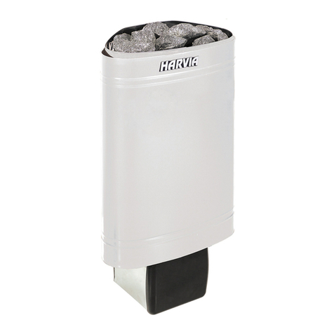
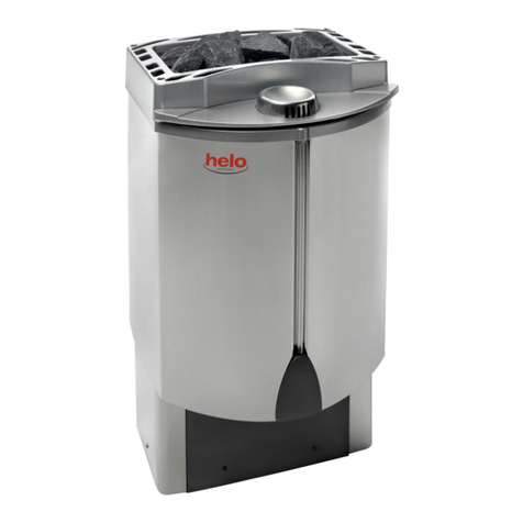
Helo ROCHER User manual

1
Instructions for installation and use
ROCHER
Electric sauna heater:
1118-700-04
1118-900-04
1118-1050-04
Contactor box:
WE – 3 400V – 415V 3N~ max 9 kW
WE – 4 400V – 415V 3N~ max 15 kW
WE – 4 – 1 230V – 240V 1N~ / 2~ max 8 kW
WE – 4 – 3 230V 3~ max 9 kW
WE – 5 – 3 230V 3~ max 15 kW
Connectable to the following control panels:
1601-12 (Control panel RA 12 Digi II)
1601-13 (Control panel RA 13 Digi I)
1601-16 (Control panel RA 16 Easy)
1601-18 (Control panel RA 18 Midi)
314 SKLT 47-2 A
GENUINE SAUNA & STEAM

2
Contents
1 Quick start guide for the sauna heater
1.1 Check list before taking a sauna bath 3
1.2 Operation of the sauna heater controls 3
2Information for users
2.1 Sauna room 3
2.2 Recommended sauna room ventilation 3
2.3 Preparing for piling the stones 4
2.4 Sauna heater stones 5
2.5 Accessories 5
2.6 Heating the sauna 5
2.7 If the sauna heater will not heat up 6
3Instructions for the installer
3.1 Preparing for sauna heater installation 6
3.2 Installation 6
3.3 Main connection 7
3.4 Electric heating toggle 7
3.5 Locating the connecting box for connection cable in the sauna room 8
3.6 Sauna heater safety clearances 8
3.7 Switch diagram 10
3.8 Installing the support for heating elements 12
3.9 Spare parts for the Rocher electric sauna heater 13
ROHS 14
Images and tables:
Image 1 Recommended sauna room ventilation 3
Image 2 Location for the connecting box 8
Image 3 Clearances in wall and corner installations 9
Image 4 Clearances in central installation 9
Image 5 Switch diagram for the sauna heater 10
Image 6 Basic installation of a sauna heater 11
Images Preparing for piling the stones 4
Images Installing the support for heating elements 12
Table 1 Connection cable and fuses 8
Table 2 Safety clearances 8
Table 3 Spare parts 13

3
1. Quick start guide for the sauna heater
1.1 Check the following before taking a sauna bath:
-The sauna room is suitable for taking a sauna bath.
-The door and the window are closed.
-The sauna heater is topped with stones that comply with the manufacturer's recommendations,
the heating elements are covered with stones, and the stones are piled sparsely.
NOTE: Structural clay tiles are not allowed.
1.2 Operation of the sauna heater controls
Refer to the specific control panel operating instructions.
2. Information for users
Persons with reduced physical and mental capacity, sensory handicap, or little experience and knowledge
about how the device is operated (e.g. children), should only operate the device while supervised or
accoding to instructions given by the persons in charge of their safety.
Make sure that children are not playing with the sauna heater.
2.1 Sauna room
The walls and ceiling of a sauna room should be thermally well insulated. All surfaces that store heat, such
as tile and stone surfaces must be insulated. It is recommended to use wooden panel cladding inside the
sauna room. If there are heat storing elements in the sauna room, such as decorative stone, glass etc., note
that these elements may extend the pre-heating period even though the saunaroom is otherwise well
insulated. (see page 6, section 3.1 Preparing for sauna heater installation)
2.2 Recommended sauna room ventilation
55
4
4
2
1
1
1
A
7
A
min
200 mm
6
3
B
3
B
C
C
C
C A
1000 mm
1. Sauna room 3. Electric sauna heater 5. Exhaust flue or channel
2. Washroom 4. Exhaust valve 6. Door to the sauna room
7. A ventilation valve can be installed here to be kept closed while the sauna is heated and during bathing.
Inlet vent can be positioned in the A zone. Make sure the incoming fresh air will not interfere with (i.e. cool down) the sauna
heater's thermostat near the ceiling.
The B zone serves as the incoming air zone, if the sauna room isn't fitted with forced ventilation. In this case, the exhaust valve
is installed min 1m higher than the inlet valve.
DO NOT ISTALL INLET VALVE WITHIN ZONE C, IF THE SAUNA HEATER'S CONTROL THERMOSTAT IS
LOCATED AT THE SAME ZONE.

4
2.3 Preparing for piling the stones
Removing of the supporting bars to pile the stones
Unscrew the bars' mounting screws (2 pcs).
Lift the support bar's locking plate up from its
normal position.
Lift off the support bars.
Pile stones up to the Helo marker.
Reinstall the support bars.
Install the support bars as above in the reversed
order.
Pile the stones so that they cover the
heating elements.
For specific instructions refer to section 2.4 Sauna
heater stones.

5
2.4 Sauna heater stones
Quality stones meet the following requirements:
1. Sauna stones should withstand heat and heat variation caused by vaporisation of the water thrown on
the stones.
2. Stones should be rinsed before use in order to avoid odour and dust.
3. Sauna stones should have an uneven surface to supply a larger surface for the water to evaporate from.
4. Sauna stones should be large enough (intended for large sauna heaters, approx. 80 - 120mm), to allow
good ventilation between the stones. This extends the useful life of the heating elements.
5. Sauna stones should be piled sparsely in order to enhance ventilation between the stones. Do not bend
the heating elements together or against the frame.
6. Rearrange the stones regularly (at least once a year) and replace small and broken stones with new, larger
stones.
7. Stones should be piled so that they cover the heating elements. Do not, however, pile a large heap of
stones on the heating elements. For sufficient amount of stones refer to Table 2 on page 8. Any small
stones included in the stone delivery package should not be placed on the sauna heater, because they
might fall trought the heater's vertical beams.
The warranty does not cover defects resulting from poor ventilation caused by small and tightly packed
stones.
Structural clay tiles are not allowed. They may cause damage to the sauna heater Damages caused by using
structural clay tiles will not be covered by the warranty.
2.5 Accessories for Rocher sauna heater
Integration flange, soapstone EAN 6416976384299
Integration flange, frosted glass EAN 6416976384374
Led Drive optical fibre light EAN 6416976384893
2.6 Heating the sauna
Before turning the sauna heater on, make sure the sauna room is suitable for taking a sauna bath. When
heated for the first time, the sauna heater may emit some odour. If you detect any odour while the sauna
heater warms up, disconnect the sauna heater briefly, and air the room. Then turn the sauna heater back
on.
The sauna heater is turned on from the control panel that has controls for the heating temperature and
time.
You should turn the sauna heater on roughly an hour before you plan to take a sauna bath, so that the
stones have time to heat up properly and the air warms up evenly in the sauna room.
Do not put any objects on the sauna heater. Do not dry clothes on the sauna heater or anywhere
in its vicinity.

6
2.7 If the sauna heater will not heat up
If the sauna heater will not heat up, please check the following:
-The power is on;
- The fuses for the sauna heater are intact;
- Any error messages on the control panel; In case of an error message, please refer to
the control panel operating instructions.
3. Instructions for the installer
THE PERSON INSTALLING THE SAUNA HEATER SHOULD LEAVE THESE INSTRUCTIONS
IN THE PREMISES FOR THE FUTURE USER.
3.1 Preparing for sauna heater installation
Check the following before installing the sauna heater:
1. The ratio of the heater's input (kW) and the sauna room's volume (m3). Volume/input
recommendations are presented in Table 2 on page 8. The minimum and maximum volumes must not
be exceeded.
2. The sauna room ceiling must be min 1900 mm high.
3. Glass and stone surfaces will extend the pre-heating period. Each square meter of glass or stone ceiling
or wall adds 1.2m3to the sauna room's volume in terms of needed heater input.
4. Check Table 1 on page 8 for a suitable fuse size (A) and the correct diameter of the power supply cable
(mm²) for the sauna heater in question.
5. Conform to the safety clearance around the sauna heater as specified in Table 2 on page 8. There
should be enough room around the sauna heater for maintenance purposes, a doorway etc.
6. If the the heater is integrated in the sauna benches, the bench model must allow lifting of the lower
bench and its frame without tools. The warranty will not cover dismantling and reassembly of sauna
benches.
3.2 Installing the sauna heater
Follow the safety clearance specifications in table 2 and images 3 and 4 on pages 8 and 9 when
installing the sauna heater.
The sauna heater is a free-standing model. The base must be solid, because the sauna heater weighs about
120 kg.
The sauna heater is levelled by the adjustable legs.
The sauna heater is fixed on the floor from its legs by the provided metal fasteners (2 pcs). This will keep
the safety clearances intact during use.
Walls or ceilings must not be clad light-weight cladding, such as incombustible protecting board, because
they may cause a fire hazard.
A single sauna heater is allowed per one sauna room.

7
3.3 Main connection
The sauna heater must be connected to the mains by a qualified electrician and in compliance with
current regulations. Sauna heater is connected with a semi-permanent connection. Use H07RN-F
(60245 IEC 66) cables or a corresponding type. (See Table 1 on page 8) Other output cables (signal
lamp, electric heating toggle) must also adhere to these recommendations. Do not use PVC insulated
cable as a connection cable for the sauna heater.
A multipolar (e.g. 7-pole) cable is allowed, if the voltage is the same. In the absence of a separate
control current fuse, the diameter of all cables must be the same, i.e. in accordance with the front fuse.
The connecting box on the sauna wall should be located within the minimum safety clearance specified
for the sauna heater. The maximum height for the connecting box is 500 mm from the floor, (see
Image 2 on page 8) If the connecting box is located further than at 500 mm distance from the heater,
the maximum height is 1000 mm from the floor.
The sauna heater's heating elements may absorbe moisture from the air during storage etc. This may
cause leakage current. The moisture will evaporate when the sauna heater is heated a few of times. Do
not connect electric supply to the sauna heater via the fault current switch.
Adhere to the effective electrical safety regulation when installing the sauna heater.
3.4 Electric heating toggle
Electric heating toggle applies to homes with an electric heating system.
Sauna heater has a connection (marked 55) for controlling the electric heating toggle. Connector 55 and
the heating elements are simultaneously live (230V).

8
Table 1
Input Sauna heater's Fuse Sauna heater's Fuse Sauna heater's Fuse
connection cable connection cable connection cable
H07RN-F H07RN-F/ H07RN-F/
60245 IEC 66 60245 IEC 66 60245 IEC 66
kW mm2A mm2A mm2 A
400 - 415V 3N~ 230 V 3~ 230 - 240V 1N~ / 2~
6,8 5 x 1,5 3 x 10 4 x 2,5 3 x 16 3 x 6 1 x 35
9,0 5 x 2,5 3 x 16 4 x 6 3 x 25 ------- -----
10,5 5 x 2,5 3 x 16 4 x 6 3 x 35 ------- -----
3.5 Locating the connecting box for connection cable in the sauna room
200 mm
500 mm
A A
3.
2.
1.
500 mm
Image 2
A = Speficed minimum clearance
1. Recommended location for the connecting box
2. Silumin box recommended in this area.
3. This area should be avoided. Always use a silumin box.
In other areas, use a heat-resisting box (T 125 °C) and heat-resisting cables (T 170 °C). The connecting
box must be clear of obstacles. When installing the connecting box to zones 2 or 3, refer to the
instructions and regulations of the local energy supplier.
3.6 Sauna heater
safety clearances
Table 2
Sauna room Safety clearances
min.
H A D F
kW m3m3 mm mm mm mm ca.kg
6,8 5 9 1900 60 60 770 100
9,0 8 13 1900 60 60 770 100
10,5 9 15 1900 60 60 770 100
Input
minimi
maximi
Height min
on the
sides
at the
front
to the
ceiling
adequate
amount of
stones

9
Image. 3 and 4
1900
60
mm
mm
60
770
60
60
40 *)
OLET 19
425 mm
1130
OLET 19
1900
60
mm
60
770
OLET 19
OLET 19
ADF
H
AA
F
H
*)
*)
*)
Corner and wall installation
Fixing the sauna heater
on the floor. NOTE
fixing of two (2) legs
Absolute measurement! (must not be exceeded
or undershot)
Middle installation:
Golv-
fästkruv
Adjustable
leg
Floor
fastener
Hearters
leg
Metal
fastener
Safety clearances between the bottom of the sauna
heater and a wall.
NOTE! If the sauna heater is installed further than 60mm off a wall or a
corner, the installation method is always middle installation. The
thermostat must be installed in the ceiling, as per instructions.

10
3.7 Switch diagram
Image. 5
2
3
1
1.
1. Syöttö / Nätet / Stromnetz / Power input.
N L1 L2 L3
1 2 3 4 5 6
400V - 415V 3N~
Teho, Effekt
Input, Leistung
kW
Lämpövastukset, Värmeelement,
Heating elements, Heizeelement
6,8
9,0
10,5
230 V
SEPC 199 SEPC 201 SEPC 200
2267W 3000W 3500W
1,2,3
354 SKLT
1,2,3
1,2,3

11
Control unit Sensor cable
4
3
2
1
4
3
2
1
Limiter
Connector strip
1 Sin
2 Valk.
3 Pun
4 Kelt
1 Sin
2 Valk.
3 Pun
4 Kelt
A 1 2 3 4 5 B1 2 3 4 5
A 1 2 3 4 5 B1 2 3 4 5
Sauna heater Central 1601-12
A1 Valk Vit White Weiss
A2 Ruskea Brun Brown Braun
A3 Vihreä Grön Green Grün
A4 Kelt Gul Yellow Gelb
A5 Harm Grå Grey Grau
B1 Rosa Ljusröd Pink Rose
B2 Sin Blå Blue Blau
B3 Pun Röd Red Rot
B4 Musta Svart Black Schwarz
B5 Violetti Violett Violet Violett
Control panel
1601-12
Periaatekuva
Silicone 4 x 0,25
LiYY 10 x 0,25
Power input
230V - 240V 1N~ / 2~
230V 3~
400V - 415V 3N~
Sauna heater
Image of principle with control panel Digi II.
Image 6
OLET 19
Contactor box
WE-3
WE-4-1
WE-4-3
WE-5-1
WE 5-3
Support for
heating element

12
3.8 Installing the support for heating elements: Pile in stones up to halfway of the provided space.
Position the support so that the heating elements stay between the openings. Tilt the support and press
the pivots at each end of the support to the grooves in the inside of the heater's vertical beams, one end
at a time. The support for heating elements should stay levelled.
Position the support between the
heating elements.
Push the pivots at one end of the
support to the grooves in the
vertical beams.
Press the pivots at the other end of
the support to the grooves in the
heater's vertical beams.
Subsequently, pile in stones up to
the upper edge so that they cover
the heating elements.

13
3.9 Spare parts to ROCHER sauna heater:
Table 3
Product number Product title Rocher 700 Rocher 900 Rocher 1050
1 Mains connector NLWD
1-1
7812550 1 1 1
2 Heating element SEPC
199 2267W / 230V
5207770 3
3 Heating element SEPC
201 3000W / 230V
5207772 3
4 Heating element SEPC
200 3500W / 230V
5207771 3

14
ROHS
Instructies ter bescherming van het milieu
Dit product mag aan het einde van de levensduur niet
worden weggegooid via het normale huishoudafval. In plaats
daarvan moet het worden afgegeven bij een inzamelplaats
voor het recyclen van elektrische en elektronische apparaten.
Dit is waar het symbool op het product, de
gebruiksaanwijzing of de verpakking naar verwijst.
Het materiaal kan worden gerecycled op basis van de
aangebrachte markeringen. Door hergebruik van materialen
of oude apparaten levert u een belangrijke bijdrage aan de
bescherming van ons milieu. Lever het afgedankte product af
bij de inzamelplaats zonder saunastenen of het deksel van
speksteen.
Voor vragen over de inzamelplaats kunt u contact opnemen
met de gemeente.
Instrucciones de protección medioambiental
Este producto no debe ser tratado como un residuo
doméstico normal al final de su vida útil, sino que debe
depositarse en el punto de recogida adecuado para el
reciclaje de equipos eléctricos y electrónicos.
La presencia de este símbolo en el producto, en el manual de
instrucciones o en el paquete indica lo anteriormente
mencionado.
Los materiales pueden reciclarse según las marcas que
figuren en ellos. Mediante la reutilización o
aprovechamiento de estos materiales, o la reutilización de
equipos antiguos, se contribuye de manera importante a la
protección del medio ambiente. Nota: este producto debe
entregarse en el centro de reciclaje sin las piedras de sauna ni
la cubierta de esteatita.
Para obtener información acerca del punto de reciclaje,
póngase en contacto con la administración municipal.
Instructions for environmental protection
This product must not be disposed with
normal household waste at the end of
its life cycle. Instead, it should be
delivered to a collecting place for the recycling
of electrical and electronic devices.
The symbol on the product, the
instruction manual or the
package refers to this.
The materials can be recycled according to the
markings on them. By reusing, utilising the
materials or by otherwise reusing
old equi pment , you ma ke an impor tant
contribution for the protection of our environment.
Please note that the product is returned to the recycling
centre without any sauna rocks and soapstone cover.
Please contact the municipal administration
with enquiries concerning the recycling place.
Instructions pour la protection de l’environnement
Ce produit ne doit pas être mêlé aux ordures ménagères en
fin de vie. Il doit être déposé dans un centre de collecte pour
le recyclage des appareils électriques et électroniques.
Le symbole apposé sur le produit,
la notice d’utilisation ou l’emballage
l’indique.
Les matières peuvent être recyclées conformément à leur
marquage. En réutilisant, recyclant les matières ou en
utilisant différemment un vieil équipement, vous contribuez
considérablement à la protection de l’environnement.
Attention : ce produit doit être déposé au centre de recyclage
sans pierres et sans parement en stéatite.
Veuillez contacter votre Municipalité pour connaître le
centre de recyclage.
Table of contents
Other Helo Electric Heater manuals

Helo
Helo SKSM STJ User manual

Helo
Helo Piccolo DEL Operator's manual

Helo
Helo FONDA DET User manual
Helo
Helo Fusion 60 User manual

Helo
Helo Vienna D User manual

Helo
Helo Rocher Elite User manual

Helo
Helo 1118-60-0405 Guide

Helo
Helo ROCHER DET User manual
Helo
Helo Havanna STS User manual

Helo
Helo HIMALAYA Elite User manual

Helo
Helo FONDA DUO User manual

Helo
Helo SAUNATONTTU User manual
Helo
Helo SKSM STJ Series User manual

Helo
Helo Himalaya DE User manual

Helo
Helo Laava Series User manual
Helo
Helo Cava series Guide

Helo
Helo Rocher DES User manual

Helo
Helo Havanna D Helo-WT User manual
Helo
Helo MAGMA User manual
Helo
Helo HELO CAVA DET User manual


