Heltun HE-HT01 User manual
HE-HT01 USER MANUAL 1
HEATING THERMOSTAT
HE-HT01 USER MANUAL
for Hardware v.12 & Firmware v.2.2

HE-HT01 USER MANUAL 2
TABLE OF CONTENTS
OVERVIEW...................................................................................................................................................3
TECHNICAL SPECIFICATIONS...................................................................................................................4
FUNCTIONS & FEATURES..........................................................................................................................4
INSTALLATION.............................................................................................................................................5
DISASSEMBLY.............................................................................................................................................7
TOUCH PANEL OPERATION.......................................................................................................................8
OPERATION MODES...................................................................................................................................8
COM - Comfort Mode (Heat......................................................................................................................9
TIME - Temperature Schedule Mode (Auto Changeover) ........................................................................9
DRY - Fast Floor Drying Mode (Dry Air) .................................................................................................10
ECO - Energy Saving Mode (Energy Save Heat)...................................................................................11
VAC - Vacation Mode (Away).................................................................................................................11
MAN - Manual Control Mode (Off)..........................................................................................................11
CHILD LOCK (LOC)....................................................................................................................................11
FACTORY RESET (RES) ...........................................................................................................................11
Z-WAVE NETWORK...................................................................................................................................12
Adding to Z-Wave network .....................................................................................................................12
Removing from Z-Wave network ............................................................................................................12
Security...................................................................................................................................................13
SmartStart...............................................................................................................................................13
Firmware OTA Update............................................................................................................................14
Z-Wave Plus V2 Specifications...............................................................................................................14
Associations............................................................................................................................................16
SETTINGS MENU.......................................................................................................................................16
SETTINGS (available through menu and Z-Wave network)........................................................................17
Z-Wave...................................................................................................................................................19
Hardware & Software Versions...............................................................................................................20
Power and Energy Consumption............................................................................................................20
Display Brightness..................................................................................................................................21
Touch Sensitivity.....................................................................................................................................21
Input & Output Configurations.................................................................................................................21
Temperature Configurations...................................................................................................................22
Time Configurations................................................................................................................................25
SETTINGS (available through Z-Wave network only).................................................................................25
Time Mode Schedule..............................................................................................................................26
Sensors Report Interval..........................................................................................................................26
Association Commands Action...............................................................................................................27
PARAMETERS LIST & FACTORY DEFAULTS..........................................................................................28
LIMITED WARRANTY ................................................................................................................................32

HE-HT01 USER MANUAL 3
OVERVIEW
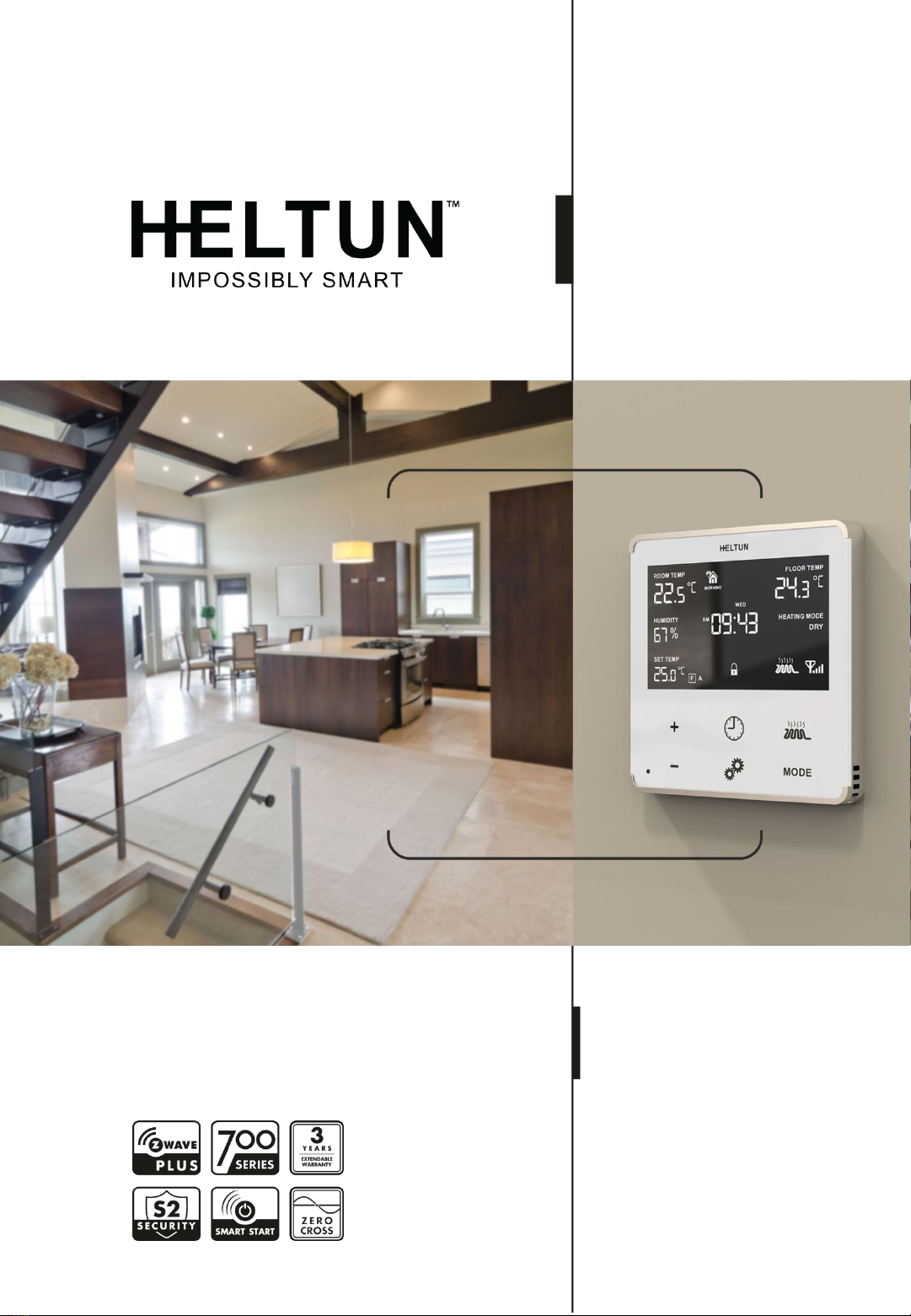
This is the user manual for HELTUN HE-HT01 Advanced Programmable Thermostat for
Heating Systems. The HE-HT01 is elegantly designed and ‗Impossibly Smart‘ providing
wireless over-the-Internet control of your home‘s heating system. The HE-HT01 is
‗Impossibly Thin‘ on the wall yet packed with features to help you save energy while
providing the ultimate comfort and convenience.
Controls electric heating systems
The HE-HT01 is designed to maintain constant room and floor temperatures by providing
sensors for both ambient and radiant floor heating systems. It controls electric heating
systems like radiators, convection or electric fireplaces, plus boilers, and electric underfloor
heating. Heating elements are directly controlled via a 16 Amp switch.
Multiple built-in sensors
The HE-HT01 has an LCD screen, six high sensitivity capacitive touch buttons, and two
temperature sensors for monitoring: ambient air temperatures, and floor temperatures using
the included external NTC sensor. It is also equipped with built-in sensors for: humidity,
illumination, and energy consumption. You can instantly access information from all
sensors on the user-friendly display.
Monitor all important information without even atouch
The at-a-glance display shows: ambient air temperature, floor temperature, user set point,
humidity level, current operating mode, time, day of the week, and status of the Z-Wave™
network & relay. Display brightness adjusts to ambient light conditions automatically making
it always easy to read.
Highly configurable with automatic safety
You can select one of six operation modes with individual set points either manually, or by
using a Z-Wave controller/gateway. As a safety measure, the HE-HT01 protects radiant
floor systems from overheating by automatically switching off if the floor temperature
reaches 40°C.
Know how much energy you use
The HE-HT01 built-in Power Consumption System precisely monitors how much energy
you used during any particular day, week, or month.
Based on the latest Z-Wave platform
The HE-HT01 integrates a Z-Wave Plus™ v2 700 platform module allowing it to be used
with Z-Wave home automation systems. The HE-HT01 supports Z-Wave ‗S0‘ and ‗S2‘
security protocols, SmartStart technology, and can be connected (―associated‖) to other Z-
Wave devices, such as relays, switches, etc.

HE-HT01 USER MANUAL 4
TECHNICAL SPECIFICATIONS
Front frame (on wall) dimensions:
89mm (H) х 89mm (W) х 9mm (D)
Rear electronics package
dimensions: 53mm (H) х 53mm (W) х
28mm (D)
Materials: Tempered glass
display/body, Flame retardant plastic
4 frame colors: White, Matte
Black, Silver, Chrome
6 glass colors: White, Black,
Yellow, Green, Red, Blue
LCD: 72mm x 42mm (3.3 inch),
black with white segments
6 capacitive-touch buttons
Operating temperature: 0°С to +50°С
Power supply: 85-265VAC
50Hz/60Hz, 24-48VDC
Power consumption: 1W
Maximum resistive load: 16А, 4000W
@ 250VAC
HELTUN Advanced Zero-Cross
relay switching technology
Relay life time: 100.000 switches
Internal ambient light sensor
Internal temperature sensor
Measurement range: –30°C to
+80°C
Accuracy: ±0.5°C
Internal humidity sensor
Measurement range: 0% to
80%RH
Accuracy: ±3.0%RH
External floor temperature sensor
NTC 10kΩ
Measurement range: -30°C to
+80°C
Accuracy: ±0.5°C
Real time energy consumption
meter
IP class: IP21
Z-Wave Plus V2 SDK: V7.11
Z-Wave module: ZGM130S
Requires mounting to flush
electrical junction box: round or
square type –min. depth 40mm
FUNCTIONS & FEATURES
Options for Inclusion/Exclusion to/from
Z-Wave network
Non-Secure
S0 Secure
S2 Unauthorized, S2 Authorized
with Key
Association control of Z-Wave
devices in network
6 operational modes with
individual temperature set points:
COM –Comfort/Heating Mode
ECO –Energy saving Mode
VAC –Vacation/Away Mode
DRY –Floor Dry Mode
TIME –Schedule Mode
MAN –Manual Control Mode
4 time schedules for 7 days of the
week:
Morning
Day
Evening
Night
Temperature sensor selection:
Floor temperature only
Air temperature only
Floor + Air temperature
Power regulator (Automatic
ON/OFF timer)
Can be used with different NTC-
sensors (range: 1kΩ to 100kΩ)
Periodic measurements from:
Internal temperature sensor
External floor temperature sensor
Internal humidity sensor
Internal ambient light sensor
Energy consumption meter
Calibration of Internal Room
Air Temperature Sensor
Calibration of External NTC
Temperature Sensor
Temperature set intervals: 1.0°C
to 37.0°C
HE-HT01 USER MANUAL 5
Temperature limiter: 40.0°C
Temperature hysteresis selection
range: 0.2°C to 10.0°C
Relay output NO / NC mode
HELTUN Advanced Zero-Cross
Relay switching technology
Time format: 24 or 12 hours
(AM/PM) LCD brightness:
LCD brightness
Automatic adjustment
(depending on ambient light)
Manual adjustment (10 levels).
LCD standby mode (different
brightness for active and inactive
states)
LCD backlight blinking function (for
easy identification among other Z-Wave
devices)
Child lock mode (touch buttons
lockout mode)
Real-time and cumulative energy
usage to 0.1kW accuracy
Factory reset function
SmartStart technology for quick
addition to Z-Wave networks
Encrypted OTA (Over The Air)
firmware update feature
INSTALLATION
HELTUN recommends the HE-HT01 thermostat be installed by a licensed electrician in a
manner that conforms to local regulations and building codes. Provide these instructions to
the licensed electrician who is installing the HE-HT01.
≡Note: It is not recommended to install the device in rooms with high humidity
such as bathroom or sauna.
WARNING: ELECTRICAL POWER MUST BE SWITCHED OFF DURING INSTALLATION.
1. Placement of the HE-HT01 is of utmost importance for proper operation and must
be away from sunlight and sources of direct heat. We recommend installing the HE-
HT01 approximately 1.5 meters above the floor.
2. Remove the display unit and backplate of the HE-HT01 from the packaging.
3. FIRST ENSURE THE POWER IS OFF at the main circuit breaker, and then test the
wires with a probe or multimeter to verify. Insert the power and heater wires to the
correct HE-HT01 terminals by inserting a small Phillips-head screwdriver in the slot
beneath each terminal to open. Follow the connection diagrams and instructionsbelow:
▪Power wires: connect Line & Neutral wires to L & N terminals labeled ―IN‖
▪Heater wires: connect Line & Neutral wires to L & N terminals labeled with ―heating
element‖ graphic

HE-HT01 USER MANUAL 6
Connection Diagram 1
Connection Diagram 3
Connection Diagram 2
Connection Diagram 4
≡Note: HELTUN recommends installing cord terminals (electric wire ferrule) on the
ends of wires before connecting them to the HE-HT01 (various colors terminals are
included in the packaging).
≡Note: If using the HE-HT01 for radiant floor heating, connect the NTC temperature
sensor wire to the terminals labeled ―NTC.‖ A 10 kΩ NTC sensor is included in the
HE-HT01 packaging, but also different NTC-sensors can be connected (range: 1kΩ
to 100kΩ).
≡Note: If an NTC sensor other than 10 kΩ is used, sensor Parameter value should
be changed in the settings menu (Parameter 10 –FSr) –see ―Settings Menu‖
section below.
4. If you will be using an external device to select modes for the HE-HT01 (such as a
security system), connect wires from the external device‘s dry contacts according to
connection diagrams 1 (or 2 or 3 or 4).
≡Note: There could be ―EXT‖ label instead of ―S1‖, ―Sx‖.
HE-HT01 USER MANUAL 7
5. Make sure the HE-HT01 backplate is oriented on the wall with the word ―TOP‖
pointed upwards, secure the backplate onto the electrical junction box using the four
provided screws (do not overtighten). Once the backplate is secured onto the wall,
assemble the HE-HT01 display unit onto the backplate by first carefully aligning the two
top snap connectors, and then gently pushing the entire display unit until it ‗snaps‘ into
position all the way around.
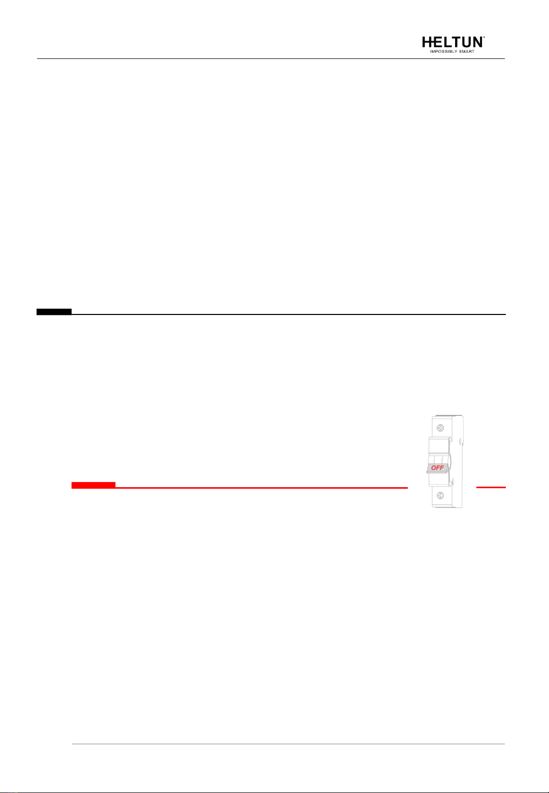
6. Next, switch On the main power at the circuit breaker (see photo above). The HE-HT01
will start up showing the original default factory settings.
7. Remove the clear protective film from the display unit and frame by pulling on the top
right-hand orange color tabs.
≡Note: Zero-Cross technology is unavailable if the device operates using DC
voltage (24-48VDC).
123
DISASSEMBLY
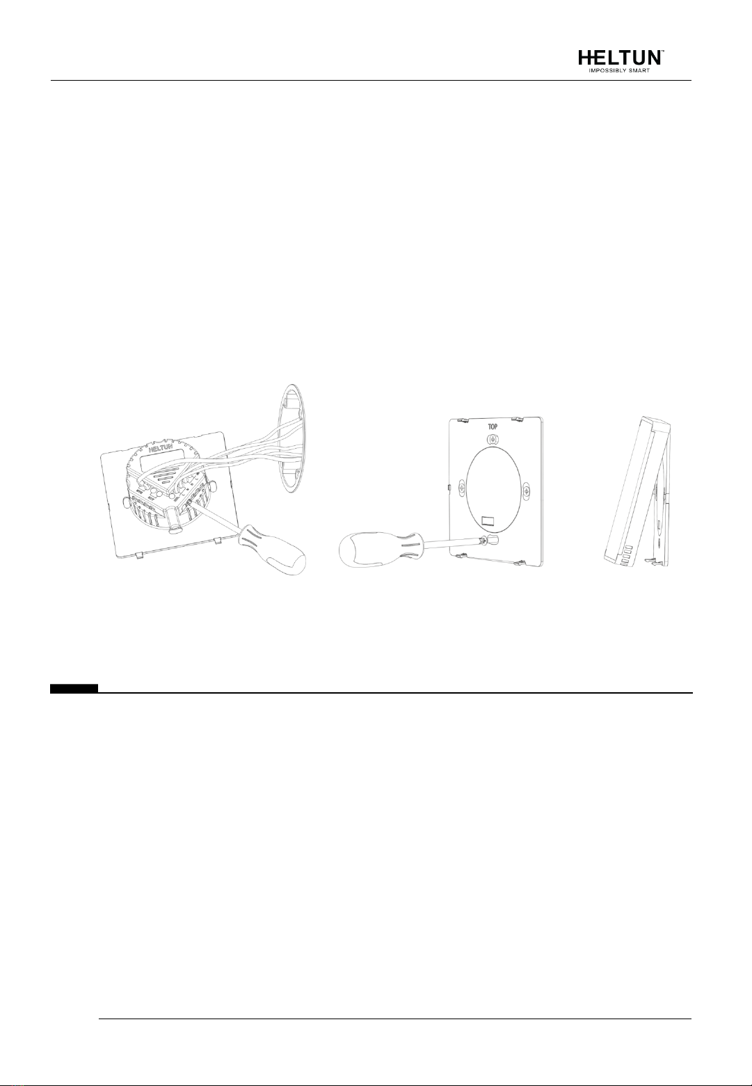
1. To disassemble, ENSURE POWER IS SWITCHED OFF at the main circuit breaker
AND THE LCD SCREEN IS BLANK.
2. To remove the HE-HT01 display unit grasp firmly at the bottom and pull backwards
while tilting outwards until all tabs are disconnected.
3. Remove screws from backplate and disconnect the wires by inserting a small Phillips-
head screwdriver into the slot beneath each wire and turning counter-clockwise to
release.

HE-HT01 USER MANUAL 8
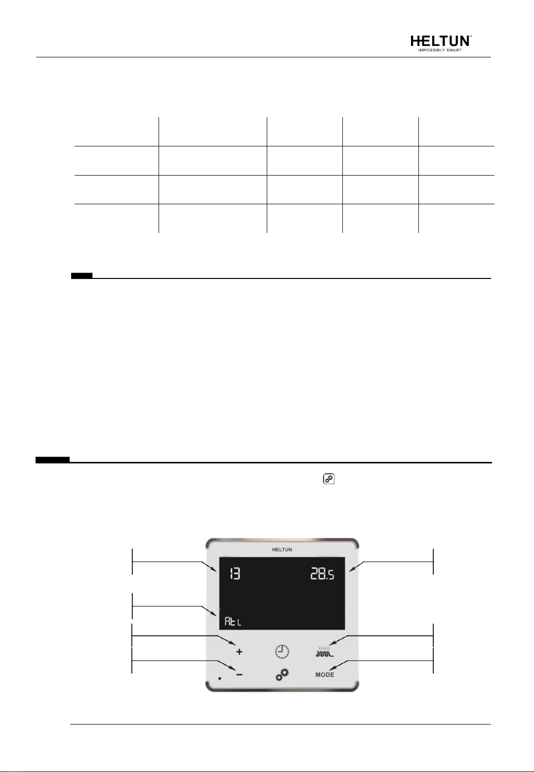
TOUCH PANEL OPERATION
The touch panel has six capacitive-touch buttons which require minimal pressure to operate.
The Plus ―+‖button will increase Set Point temperature by 0.5°C with each touch. The
Minus ―–―button will decrease Set Point temperature by the same 0.5°C. The Set Point
temperature is displayed in the bottom left corner of the LCD display under ―SET TEMP.‖
≡Note: The minimum Set Point is 1.0°C and the maximum Set Point is 37.0°C.
The HE-HT01 has two working modes: HEATING (switched On) and IDLE (switched Off).
In HEATING mode, the heating element icon will appear near the right bottom corner of
the display (to the left of the connectivity icon). The heating element icon will disappear
when the HE-HT01 is in IDLE mode.
OPERATING MODES
The current Operating Mode is shown on the middle right of the LCD display under the
label: ―HEATING MODE.‖
The HE-HT01 has 6 Operating Modes:
COM –Comfort Mode (Heat)
TIME –Time Mode (Auto Changeover - schedule different Set Point per time and day)
DRY –Floor Drying Mode (Dry Air)
ECO –Power Efficient Mode (Energy Save Heat)
VAC –Vacation Mode (Away)
MAN –Manual Control Mode (Off)
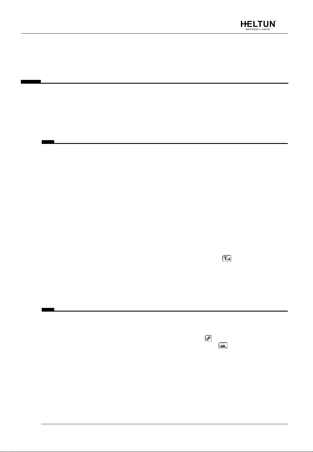
Change Modes by touching the “MODE” button (bottom right of display unit) until the
desired Mode is reached. Each operating mode has individual temperature Set Points. The
HE-HT01 will operate automatically depending on the current Set Point indicated under the
“SET TEMP” label on the LCD. To change the Set Point value, choose the desired mode
and press Plus “+” button to increase, or Minus “–” button to decrease the corresponding
Operating
mode selection
Manual
ON / OFF
Set temperature
decrease
Set temperature
increase
Settings menu
Temperature
schedule

HE-HT01 USER MANUAL 9
Set Point value. You may alternatively control Set Points through your Z-Wave gateway
software.
COM - Comfort Mode (Heat)
This mode is recommended for maximum comfort. The factory default set point is 25.0°C.
≡Note: In your Z-Wave gateway this mode will be shown as“Heat”.
TIME - Temperature Schedule Mode (Auto Changeover)
The Temperature Schedule (TIME) Mode can adjust home temperatures automatically to
align with your personal habits, saving energy while you are away, and maintaining a
comfortable temperature while you are active at home.
The HE-HT01 can have different
Schedules for Morning, Daytime, Evening
and Night. For example, the ―Morning‖
Schedule could be set to 22.0°C
starting at 6:00. The ―Day‖
Schedule could then be set to 17.0°C at
9:00 when everyone has gone to work
or school, and so on. Here are
recommended Scheduled Set Points for
heating during the work week –you may
wish to change these on weekends
depending on your family‘s schedule
(see example below):
Schedule Mode
Set Time
Set Point Temperature
Morning
6:00 (6:00 AM)
22°C
Day
9:00 (9:00 AM)
17°C
Evening
18:00 (6:00 PM)
21°C
Nigh
23:00 (11:00 PM)
18°C
To set up the time and temperature for each Schedule press and hold the Clock button
for three seconds. The display will change to the Time menu.
To set up the start time for each Schedule, choose the Schedule by pressing the Clock
button then adjust the time by pressing the Heating Element button to increase, or
―MODE‖ button to decrease. Press the Clock button again to advance to the next
schedule and set the time for all four: Morning, Day, Evening & Night.

HE-HT01 USER MANUAL 10
To choose the temperature Set Points for each Schedule, choose the day of the week by
pressing the Gear button, then choose the Schedule by pressing the Clock button and
adjust the temperature Set Point up or down by pressing the Plus ―+‖ or Minus ―–― buttons.
Do this action for each day of the week.
≡Note: Time for all four Schedules (Morning, Day, Evening, & Night) are the same
for all seven days of the week.
≡Note: TIME mode will work properly only if the correct current time and date have
been set. The time can be automatically corrected from your Z-Wave
gateway if the Parameter 19 value is set to 1. Or it can be set manually in
Parameters 21 and 22 in the Settings Menu (see below).
≡Note: While in TIME mode, the temperature Set Point (under the label ―SET
TEMP‖on the LCD) will be automatically changed depending on the Schedule.
The Set Point can be adjusted up or down manually at any time, but it will be
effective only until the next Schedule.
≡Note: In your Z-Wave gateway this mode will be shown as ―Auto Changeover‖.
DRY - Fast Floor Drying Mode (Dry Air)
This mode is recommended for use if a high floor temperature is required for a limited
period of time. For example, after washing the floor. By choosing DRY Mode, the HE-HT01
will increase the temperature to the selected Set Point for the time specified in the ―Dry
Time‖ Parameter (Parameter 25). A time range of 5 to 90 minutes can be set. As the Dry
Time passes, the HE-HT01 will automatically change to the Mode set in Parameter 26.
To change the Dry Time Parameter, open the ―Settings Menu‖ by pressing the Gears
button for three seconds. Use the and ―MODE‖ buttons to scroll up and down through
the menu to Parameter 25. Then use buttons ―+‖ and ―–‖ to increase or reduce the Dry Time
setting (in minutes).
To choose the mode to revert to after Dry Time has elapsed (while still in the Settings
Menu), press the or ―MODE‖ button to select Parameter 26, then use buttons ―+‖ and ―–
‖ to choose the desired Mode as follows:
Mode:
Value:
Notes:
COM
1
This is the factory default for revert after DRY Mode (Parameter 26)
TIME
2
DRY
n/a
You cannot revert to DRY Mode.
ECO
4
VAC
5
MAN
6
If MAN Mode is chosen, the HE-HT01 will select IDLE state

HE-HT01 USER MANUAL 11
≡Note: Factory default values for Dry Time are: 30 minutes at 30.0°C.
≡Note: In your Z-Wave gateway this mode will be shown as ―Dry Air‖.
ECO - Energy Saving Mode (Energy Save Heat)
This Mode can be used if lower temperature and energy consumption are desired. It can
also be used at night or when the property is not occupied for prolonged period of time. The
factory default ECO Set Point is 20.0°C.
≡Note: In your Z-Wave gateway this mode will be shown as“Energy Save Heat”.
VAC - Vacation Mode (Away)
Use Vacation Mode when you are planning to be away from home for some period. The
factory default temperature Set Point is 15.0°C.
≡Note: In your Z-Wave gateway this mode will be shown as ―Away‖.
≡Note: The minimum set point for each mode is 1.0°C and the maximum set
point is 37.0°C.
MAN - Manual Control Mode (Off)
In this Mode the HE-HT01 schedules are disabled and the heating state is switched On &
Off manually by pressing the Heating Element button.
≡Note: When in Manual Control Mode the ―SET TEMP‖ will indicate ―OFF‖.
≡Note: In your Z-Wave gateway this mode will be shown as ―OFF‖.
CHILD LOCK (LOC)
The Child Lock feature allows you to disable the HE-HT01 touch buttons temporarily. To
activate the Child Lock Mode, press and hold the Heating Element button for five
seconds until the Lock Icon appears in the bottom center of the display. To deactivate
the Child Lock, press the HeatingElement button until the Lock Icon disappears
FACTORY RESET (RES)
By pressing and holding the ―MODE‖ button for six seconds, the HE-HT01 will enter Factory
Reset Mode, displaying ―ГEs‖ in the left bottom corner, ―y‖ in top left corner and ―n‖ in top
right corner. Press the Plus ―+‖ button to revert to factory settings, or the Heating Element
button to cancel. The factory reset will change all the Parameters to their original factory
default values (including Z-Wave frequency) and will also Exclude the device from any Z-
Wave network.
HE-HT01 USER MANUAL 12
≡Note: Please use Factory Reset only when the primary network controller is
missing or otherwise inoperable.
Z-WAVE NETWORK
The HE-HT01 may be operated in any Z-Wave network with other Z-Wave certified devices
from other manufacturers. The HELTUN HE-HT01 will act as a ‗repeater‘ (i.e. ‗range
extender‘) for other devices regardless of manufacturer or brand to increase the reliability of
the overall network.
Adding to Z-Wave network
To add HE-HT01 into a Z-Wave network (i.e. ―Inclusion‖) do the following:
1. Enter ―SETTINGS‖ Mode by pressing and holding the Gear button for three seconds.
2. If you need to change the device factory default Z-Wave frequency, see the Parameter
1 description and steps to change the value on page 12.
3. Scroll menu to ―Parameter 2 –nEt‖. The current state of the network will be displayed
in the Parameter Value position (upper right). It should display ―ECL‖.
≡Note: If ―InC‖is displayed, the HE-HT01 must first be Excluded from an existing Z-
Wave network (see ―Removing from Z-Wave network‖ below).
4. Start the Inclusion Mode from the gateway/controller.
5. On the HE-HT01 in the Parameter 2 press the Plus ―+‖button to start the Inclusion
process.
6. Note that lines will be moving in the Parameter value position (upper right).
7. ―InC‖should appear at the Parameter Value position (and the icon on the main
display bottom right corner) if Inclusion was successful.
8. If ―EСL‖or ―Err‖is on Value position (or icon on the main display bottom right
corner), the HE-HT01 Inclusion was not successful (try repeating steps 4-7).
Removing from Z-Wave network
To remove HE-HT01 from a Z-Wave network (i.e. ―Exclusion‖) do the following:
1. Enter ―SETTINGS‖ Mode by pressing and holding the Gear button for three seconds.
2. Scroll menu to ―Parameter 2 –nEt‖ using the Heating Element button to scroll up,
and the ―MODE‖ button to scroll down.
3. The current state of the network will display in the Parameter Value position (upper
right). It should display ―InC‖.
≡Note: If ―EСL‖ is displayed, the HE-HT01 is already Excluded.
4. Start the Exclusion Mode from the gateway/controller.
5. Press the Minus ―–‖ button in the HE-HT01 Parameter 2 to start the Exclusion process
6. Note that lines will be moving in the Parameter value position (upper right).
HE-HT01 USER MANUAL 13
7. ―EСL‖should appear in the value position (and icon in the bottom right corner of the
main display) if the Exclusion was successful.
8. If ―InC‖or ―Err‖in value position (or icon in the bottom right corner of the main
display) are displayed, repeat the Exclusion process.
≡Note: If the HE-HT01 has previously been part of a Z-Wave network and not
Excluded since, Inclusion is not possible without first performing an Exclusion or
Factory Reset procedure.
≡Note: If the HE-HT01 is included in the Z-Wave network the antenna icon will
appear in the bottom right corner of the main screen with signal strength bars .
Security
S0, S2 unauthorized, and S2 authorized Inclusion Modes are supported. If you use the S2
authorized Inclusion Mode the security key should be used during the inclusion process.
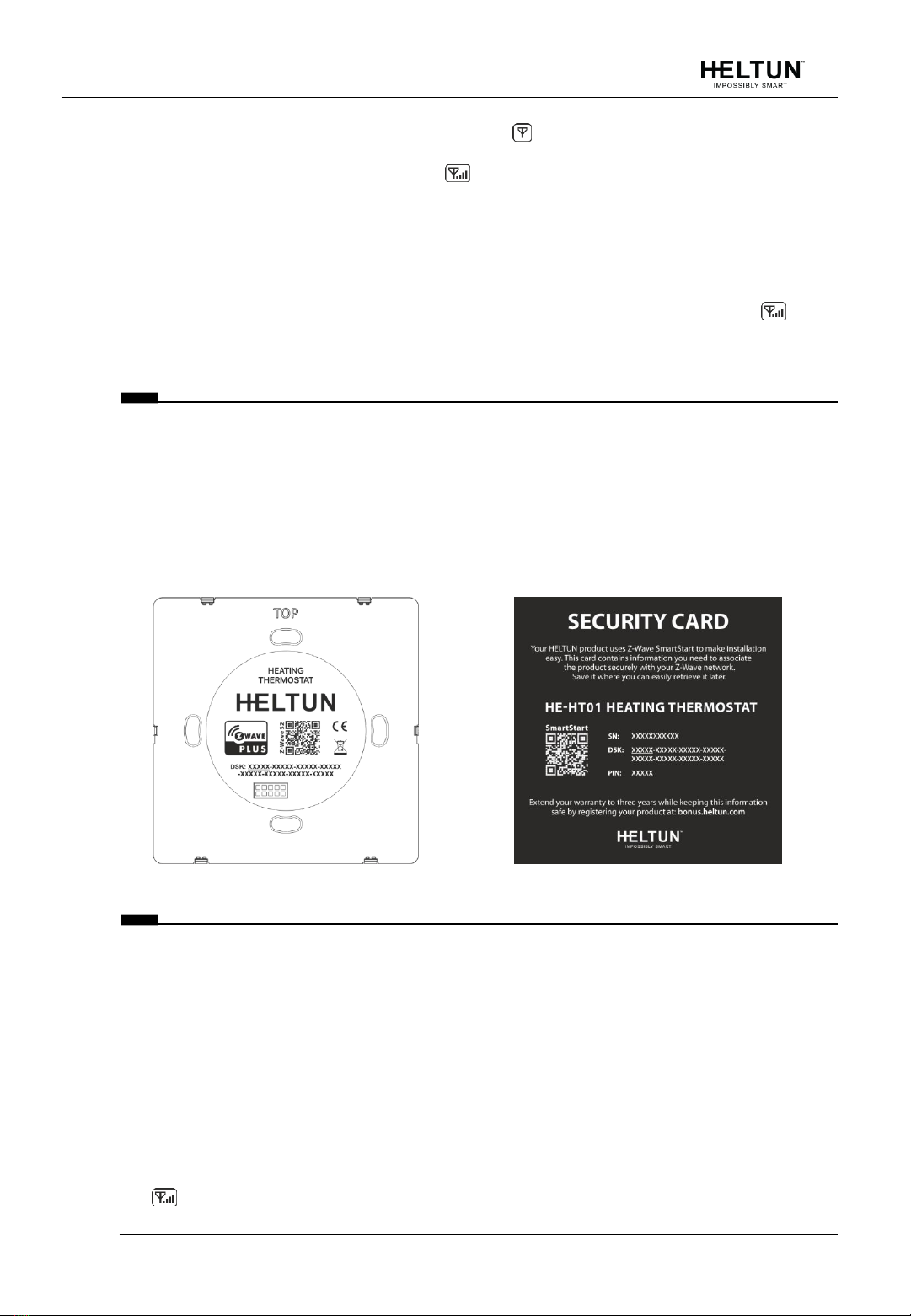
Security key is the first 5 digits of DSK (device DSK is printed on the HE-HT01 back panel
plus on the Security Card included in the packaging).
≡Note: Be sure to save this key. Without the key, it is impossible to perform an
inclusion in S2 authorized mode.
SmartStart
SmartStart-enabled products can be added to a Z-Wave network by scanning the Z-Wave
QR Code shown on the product with gateways/controllers that allow SmartStart inclusion.
In this case, no further action will be required and the SmartStart product will be added
automatically within ten minutes of being turned on in the vicinity of a network.
To add the HE-HT01 to the Z-Wave network usingSmartStart:
1. Input the thermostat DSK to the controller‘s Node Provisioning List (or scan the QR
code).
2. Power on the device.
3. Wait for the adding process to complete.
4. Successful adding will be confirmed by displaying the Antenna with signal strength bars
icon in the bottom right corner of the main screen.

HE-HT01 USER MANUAL 14
≡Note: The device DSK and QR code are printed on the HE-HT01 back panel plus
on the Security Card included in the HE-HT01 packaging.
Firmware OTA Update
To wirelessly update the HE-HT01 firmware, follow these steps:
1. Check the current firmware version (Parameter 3 in the settings).
2. Start the process from the gateway/controller.
3. Download the firmware that corresponds to the HE-HT01 (see https://support.heltun.com/).
4. Set the main controller in Firmware OTA (―over-the-air‖) Update Mode (see the
gateway/controller manual).
5. As soon as the Firmware update begins, ―LOAd‖text will be displayed on the screen
(this will take a few minutes).
6. When the Firmware has updated, ―UPd‖will display on the screen for three seconds
and the HE-HT01 will reboot.
7. When the update has completed, the HE-HT01 will return to normal operation.
8. If desired, verify the update was successful by checking the software version in
Parameter 3 of the Settings Mode.
≡Note: Firmware update process has 8 minutes timeout. When timeout
expired, incomplete update process will be aborted.
Z-Wave Plus V2 Specifications
Generic Device Class: GENERIC_TYPE_THERMOSTAT
Specific Device Class: SPECIFIC_TYPE_THERMOSTAT_GENERAL_V2
Supported Command Classes
Command Class
Version
Required Security Class
Z-Wave Plus Info
V2
none
Association
V2
highest granted (S2 Authenticated, S2
Unauthenticated or S0)
Association Group Info
V3
highest granted (S2 Authenticated, S2
Unauthenticated or S0)
Multi Channel Association
V3
highest granted (S2 Authenticated, S2
Unauthenticated or S0)
Thermostat Operating State
V1
highest granted (S2 Authenticated, S2
Unauthenticated or S0)

HE-HT01 USER MANUAL 15
Thermostat Mode
V3
highest granted (S2 Authenticated, S2
Unauthenticated or S0)
Thermostat Setpoint
V3
highest granted (S2 Authenticated, S2
Unauthenticated or S0)
Sensor Multilevel
V11
highest granted (S2 Authenticated, S2
Unauthenticated or S0)
Meter
V5
highest granted (S2 Authenticated, S2
Unauthenticated or S0)
Clock
V1
highest granted (S2 Authenticated, S2
Unauthenticated or S0)
Transport Service
V2
none
Security 0
V1
none
Security 2
V1
none
Version
V3
highest granted (S2 Authenticated, S2
Unauthenticated or S0)
Manufacturer Specific
V2
highest granted (S2 Authenticated, S2
Unauthenticated or S0)
Device Reset Locally
V1
highest granted (S2 Authenticated, S2
Unauthenticated or S0)
Powerlevel
V1
highest granted (S2 Authenticated, S2
Unauthenticated or S0)
Supervision
V1
none
Indicator
V3
highest granted (S2 Authenticated, S2
Unauthenticated or S0)
Configuration
V4
highest granted (S2 Authenticated, S2
Unauthenticated or S0)
Application Status
V1
none
Firmware Update Meta Data
V5
highest granted (S2 Authenticated, S2
Unauthenticated or S0)
Basic
V2
highest granted (S2 Authenticated, S2
Unauthenticated or S0)
HE-HT01 USER MANUAL 16
Meter Command Class:
Meter Type
Scale
Rate Type
Precision
Size
Electric [0x01]
Electric_kWh [0x00]
Import [0x01]
2
4
Electric [0x01]
Electric_W [0x02]
Import [0x01]
0
2
Electric [0x01]
Electric_V [0x04]
Import [0x01]
0
2
Associations
Association enables the HE-HT01 to control other Z-Wave devices over the network.
Association Group may control other devices from different brands and/or manufacturers.
The HE-HT01 has two association groups:
Group 1–“Lifeline”: reports full state of the device and used to communicate with the Z-
Wave gateway. Max supported nodes: 1.
≡Note: It is not recommended to modify this group.
Group 2–“Basic Set On/Off: Relay”: is assigned to the HE-HT01 operating state. It
sends a Basic Set command with value 0 (Off) when it goes to IDLE state and sends 255
(ON) when it goes into HEATING state. Max supported nodes: 1.
SETTINGS MENU
To enter the Settings Menu, press and hold the Gear button for three seconds. The
abbreviated Parameter Name will be displayed in the bottom left corner of the LCD. The top
left corner will display the Parameter Number. And the top right corner will display the
Parameter Value.
Param Number
Param Name
Param Value
Increase
Param Value
Reduce
Param Value
Param Number
Increase
Param Number
Increase

HE-HT01 USER MANUAL 17
To scroll through the menu, press or hold the Heating Element button to go up and the
―MODE‖ button to go down. To change the Parameter value, press or hold the Plus ―+‖ or
Minus ―–‖ buttons.
To leave the Settings Menu press and hold the button for 3 seconds or just wait. If no
action is detected for 20 seconds the display will automatically revert to the main display
mode.
SETTINGS (available through menu and Z-Wave network)
All configuration parameters are accessedthrough Z-Wave
COMMAND_CLASS_CONFIGURATION
Group
Number
Name
Description
Default
Value
Value Range
Z-Wave
01
ГEg
Frequency Region
EU: Europe
US: USA
AU: Australia
HO: Hong Kong
In: India
IL: Israel
ГU: Russia
Cn: China
JP: Japan
Oг: Korea
Z-Wave
02
nEt
Inclusion / Exclusion Mode
InC, ECL
Version
03
HS
Hardware and Firmware
Versions
Read Only
Load Power
Consumption
04
LPc
Energy Consumption, kWH
Load Power, kW
Read Only
Display
Brightness
05
dbr
Display brightness control
0
0, 1 … 10
Touch
Sensitivity
06
tCH
Touch button sensitivity:
1 = Lowest sensitivity,
10 = Highest sensitivity
6
1…10
Inputs /
Outputs
Configuration
07
ГEL
Relay output NO or NC
mode
0
0, 1
08
In1
External input mode
0
0, 1, 2, 3
09
In2
Mode number for External
Input action:
1 = COM, 2 = TIME,
3 = DRY, 4 = ECO,
5 = VAC, 6 = MAN (Off#)
6
1, 2, 3, 4, 5, 6

HE-HT01 USER MANUAL 18
10
FSr
Floor Sensor Resistance,
kΩ
10
1…100
Temperature
Configuration
11
SEn
Source Sensor:
1 = A, 2 = AF, 3 = F, 4 =
FA, 5 = t, 6 = tA, 7 = tF
3
1, 2, 3, 4, 5, 6, 7
12
AtL
Air Temperature Minimum
21
1.0°C … 36.0°C
13
AtH
Air Temperature Maximum
27
2.0°C … 37.0°C
14
FtL
Floor Temperature
Minimum
18
1.0°C … 36.0°C
15
FtH
Floor Temperature
Maximum
32
2.0°C … 37.0°C
16
FtC
Floor Temperature
Calibration.
0
-10°C … 10°C
17
AtC
Air Temperature
Calibration.
0
-10°C … 10°C
18
HyS
Temperature Hysteresis.
0.5
0.2°C … 10.0°C
Time
Configuration
19
tCr
Time correction by
controller
1
0, 1
20
tFo
Time Format։0=24 hour,
1=12 hour (AM/PM)
0
0, 1
21
dAy
Day of the Week
1
1, 2, 3, 4, 5, 6, 7
22
tIA
Time Manual Adjustment -
Hour:Minutes
0
00:00 … 23:59
23
tOn
Time Regulation ON time,
min
30
10…240
24
tOF
Time Regulation OFF time,
min
30
10…240
25
dr1
Dry Time, min
30
5…90
26
dr2
Mode to revert to after
completion of Dry mode:
1 = COM, 2 = TIME, 4 = ECO,
5 = VAC, 6 = MAN (Off)
1
1, 2, 4, 5, 6

HE-HT01 USER MANUAL 19
Z-Wave
Parameter 01 (“ГEg”) – Frequency Region
The HE-HT01 has Z-Wave 700 series chip inside which allows to use the device in different
Z-Wave frequencies. If there is a need to use the device in the frequency different from the
factory default, change the value of this Parameter according to the frequency list below.
Modification is possible only while the HE-HT01 is not included to Z-Wave network. While
the device is included, the Antenna Icon is shown at the bottom right corner of the LCD
main screen and modification of this Parameter is disabled.
To navigate through different values from menu use the Plus ―+‖and Minus ―–―buttons.
After the Frequency Region has been selected (according to the frequency list below), hold
the Clock button for 3 seconds to save the Parameter value. The device will reboot for
the new settings to take effect.
≡Note: The factory default frequency differs depending on which region the device
was intended for sale in. Check the factory default frequency on the device plate
or on the packaging.
≡Note: Do not change this Parameter value if there is no special need.
≡Note: If change the value of this Parameter through Z-Wave network, the
frequency change will be applied only after removing the device from Z-Wave
network (the device will automatically reboot)․
≡Note: The change of this Parameter will result in inability to control the device, if
the device was included to the controller/gateway which supports only one
frequency.
≡Note: Resetting the device to factory default settings will revert the frequency to
the factory default value.
≡Note: In most of countries it is not allowed to use the frequency different from
the frequency intended for that country.
Frequency list for different regions:
0: EU (868.4 MHz, 869.85 MHz)
1: US (908.4 MHz, 916.0 MHz)
2: AU (919.8 MHz, 921.4 MHz)
3: HO (919.8 MHz)
4: In (865.2 MHz)
5: IL (916.0 MHz)
6: RU (869.0 MHz)
7: Cn (868.4 MHz)
8: JP (922.5 MHz, 923.9 MHz, 926.3 MHz)
9: Or (920.9 MHz, 921.7 MHz, 923.1 MHz)
The full list of Z-Wave global regions where Z-Wave works is available at Z-Wave Global
Regions SiLabs page.
Parameter 02 (“nEt”) –Inclusion /Exclusion to /from Z-Wave Network
If the HE-HT01 is included in a Z-Wave network, the Antenna Icon will be shown in the
LCD main screen and ―InC‖ will be indicated as this Parameter value. If it is not included in
the network, Antenna Icon will be shown in the main screen, and the Parameter value
will be ―ECL‖. To include or exclude the HE-HT01 into or from your Z-Wave network,
activate Inclusion or Exclusion Mode on your gateway, then go to Parameter 02 in the
Device Menu and press the Plus ―+‖button for Inclusion, or Minus ―–‖for Exclusion. For
more details see Z-Wave Network section of this manual.
≡Note: Through Z-Wave network this Parameter is read-only and the
modification is disabled.
HE-HT01 USER MANUAL 20
Hardware & Software Versions
Parameter 03 (“HS”) –Hardware and Software Versions
This Parameter allows you to manually check the hardware and firmware versions of the
HE-HT01 directly from the device screen. Display information follows this format: Firmware
Major Version - displayed at the Hours position, Minor Version - displayed at the Minutes
position. Hardware version - displayed at the top right corner at the Floor sensor position.
Through the Z-Wave network the Parameter returns value in the format XXYYZZ, where XX
is Hardware Version, YY is Firmware Major Version and ZZ is Firmware Minor Version.
≡Note: This Parameter is read-only in the menu and through Z-Wave network.
Power and Energy Consumption
HE-HT01 monitors Real-Time and Cumulative power Energy Consumption and Voltage
using advanced micro-controller technology which assures maximum accuracy (±1% for
loads greater than 1000W). Real-Time Consumption, Cumulative Consumption, and
network Voltage are periodically reported to the Z-Wave controller (according to the
Parameters 141 and 142), and are also accessible from the device menu:
Parameter 04 (“LPc”) –Energy Consumption values
This Parameter allows you to check the Cumulative and Real-Time Energy Consumption of
the connected load. Display information follows this format: Total Cumulative Consumption
- displayed at the time position in kWh, Real-Time Consumption - displayed at the top right
corner at the Floor sensor position in kW. Through the Z-Wave network this Parameter
returns Total Cumulative Consumption value in kW.
≡Note: This Parameter is read-only.
Resetting Cumulative Consumption memory:
The HE-HT01 Thermostat allows to erase stored Consumption Data through Z-Wave
network or manually through device menu.
Using the device menu:
1. Go to the device settings by holding the Settings button for 3 seconds
2. Go to the Parameter 04
3. Press and hold the "+" button for 3 seconds.
Using the Z-Wave network:
1. Make sure the device is powered.
2. Include the device to Z-Wave gateway / controller
3. Reset memory consumption data using Reset Command in
COMMAND_CLASS_METER (see the controller‘s manual).
≡Note: Turning the device main power off/on will not erase the consumption data as
it is stored in nonvolatile memory.
Other manuals for HE-HT01
3
Table of contents
Other Heltun Thermostat manuals

Heltun
Heltun HE-HT01 User manual

Heltun
Heltun HE-HT01 User manual

Heltun
Heltun HE-FT01 User manual

Heltun
Heltun HE-ZW-THERM-FL1 User manual

Heltun
Heltun HE-FT01 User manual

Heltun
Heltun HE-ZW-THERM-FC1 User manual

Heltun
Heltun HE-FT01 User manual

Heltun
Heltun HE-HT01 User manual

Heltun
Heltun HE-ZW-THERM-FL2 User manual


