Heltun HE-ZW-THERM-FL1 User manual

FLOOR HEATING THERMOSTAT
HE-ZW-THERM-FL1
USER MANUAL

THERMOSAT OVERVIEW & OPERATING INSTRUCTIONS
This is a programmable electronic room thermostat for flush mounting into most standard wall boxes. It is
designed to maintain a constant ambient temperature, the criteria of which can be simultaneously either
floor, room or both sensors.
It is recommended for the control of electric heating devices (radiators/convectors) or electric under floor
heating. The heating element is directly controlled by a single pole switch. The maximum loading for the
thermostat is 16A over which a contactor will be required. (16A –3600W @ 220/240V.)
The thermostat has a LCD screen, four sensitive capacitive touch control buttons and two temperature
sensors (external NTC floor sensor and a built-in room air temperature sensor). The thermostat is also
equipped with built-in humidity and energy consumption sensors.
The thermostat has a built-in 5th generation Z-Wave module which allows to integrate the device to Z-Wave
Home Automation systems such as Fibaro, Vera, Zipato and others. The thermostat can be connected with up
to 10 Z-Wave devices (relays, switchers etc.)
One of four operation modes can be selected either manually or via the Z-Wave controller. The 4 operating
modes are: DRY - floor quick drying mode, ECO –energy saving mode, GEN - general (most comfortable) mode
and manual mode. The thermostat protects the floor from overheating by automatically switching off the load
when the temperature reaches a maximum of 40°C.
The LCD screen with white icons has a user-friendly interface, displaying:
floor temperature, air temperature, humidity level, user set temperature, operating mode, relay and Z-Wave
network status.

TECHNICAL SPECIFICATIONS:
Front frame dimensions: 89х89х9mm
Back dimensions: 53х53х28mm
Material: Flame retardant plastic, tempered glass
Colour: silver frame, black or white glass
LCD: 73x42mm, black with white icons
4 sensitive capacitive touch buttons
Operating temperature: -10°С – +40°С
Power supply: 100V –230VAC, 50Hz/60Hz
Power consumption: 1.5W
Maximum resistive load: 16А 3600W
Relay life time: 100.000 switches
Internal temperature sensor
oMeasurement range: -40°C to +125°C
oAccuracy: ±0.5°C
Internal humidity sensor
oMeasurement range: 0 –80%RH
oAccuracy: ±3.0%RH
External floor temperature sensor
oNTC 10kOhm
oMeasurement range: -30°C to +80°C
oAccuracy: ±0.5°C
Energy consumption meter
IP class: IP21
Z-Wave frequency: EU-868/869 MHz
(other frequencies available on request)
Z-Wave SDK: V6.51.06
Z-Wave Plus module: ZM5202
FUNCTIONAL SPECIFICATIONS (FEATURES):
Inclusion/exclusion into/from z-wave network
Association control of 10 devices from network
4 operation modes: ECO, GEN, DRY, MANUAL
Choosing a temperature sensor for operation
Floor temperature only
Air temperature only
Floor + Air temperature
Power regulator (Automatic ON/OFF timer)
Time cycle: 10-90 minutes
Usable with different NTC-sensor
Temperature sensors calibration
Temperature set intervals: 4°C to 37°C
Temperature limiter
Choosing a temperature hysteresis
Choosing a degree (Celsius / Fahrenheit)
Adjustable LCD brightness
LCD standby mode
Child lock
Consumption meter reset
Factory reset
OTA function (Firmware update over the air).
Z-WAVE CLASSES:
CLASSES GENERIC_TYPE_THERMOSTAT
SPECIFIC_TYPE_THERMOSTAT_GENERAL_V2
COMMAND_CLASS_BASIC
COMMAND_CLASS_THERMOSTAT_SETPOINT_V3
COMMAND_CLASS_THERMOSTAT_SETBACK
COMMAND_CLASS_THERMOSTAT_MODE_V3
COMMAND_CLASS_THERMOSTAT_OPERATING_STATE
COMMAND_CLASS_SENSOR_MULTILEVEL_V7
COMMAND_CLASS_VERSION
COMMAND_CLASS_MANUFACTURER_SPECIFIC
COMMAND_CLASS_ZWAVEPLUS_INFO
COMMAND_CLASS_METER_V3
COMMAND_CLASS_DEVICE_RESET_LOCALLY
COMMAND_CLASS_POWERLEVEL
COMMAND_CLASS_CONFIGURATION_V2
COMMAND_CLASS_ASSOCIATION
COMMAND_CLASS_ASSOCIATION_GRP_INFO
COMMAND_CLASS_FIRMWARE_UPDATE_MD_V3

INSTALLATION
We recommend the installation conforms to your local regulations and is undertaken by a qualified electrical
engineer. Positioning of the thermostat is of the utmost importance and must be away from sunlight and
sources of direct heat. We recommend installation about 1.5 metres above the floor.
Electrical power must be switched off during all aspects of installation.
1. Remove the front cover and back plate of the thermostat from the main box.
2. Ensuring the power is off and using a small cross head
screwdriver connect the wires to the thermostat terminals:
IN –L: Power connection (Live)
IN –N: Power connection (Neutral)
HEATING –L: Heating Cable connection (Live)
HEATING –N: Heating Cable connection (Neutral)
3. If using the thermostat for floor heating, connect the floor
sensor wires to terminals NTC.
10 kΩ NTC sensor is included in the box but any NTC sensor
can be used.
If another sensor other than 10 kΩ NTC is used then ensure
changing the sensor value in the thermostat settings (“NTC
SENSOR” in instructions).
4. Making sure “TOP”is uppermost secure the back plate into the wall mounting box using the screws
provided. Install the thermostat body by carefully aligning the top snap connectors and then pushing
on the front cover with gentle pressure ensuring it snaps firmly into position all the way round.
5. POWER CONNECTION
Switch on the main power and the thermostat will start up showing the original default factory
settings.
6. Remove protective film by pulling the tab in the bottom left hand side.
DISASEMBLY
1. ENSURE POWER IS SWITCHED OFF AND SCREEN IS BLANK.
2. To remove thermostat body grasp firmly and pull back from the top until tabs disconnect.
3. Remove screws from back plate and disconnect the wires.
TOUCH PANEL OPERATION
The touch panel has four touch buttons which require minimal pressure to operate.
Plus
Minus
Mode
Heating
“+” key will increase set point temperature by 0.5°C (or 1°F), and “-” key will decrease set point temperature
by 0.5°C (or 1°F). The set point temperature is displayed in the bottom left corner of the display as “SET
TEMP”.
The minimum set point is 4°C (39°F) and the maximum set point is 37°C (99°F).
The thermostat has two working modes - HEATING and IDLE. In HEATING mode the operating state floor
symbol will appear on the right bottom corner of the display, and the floor symbol will disappear in IDLE
operating mode.

OPERATION MODE
Current mode is displayed in the middle of bottom line of display under “HEATING MODE” section.
The thermostat has 4 operating modes:
GEN –general (comfort) mode. Recommended normal comfort.
ECO –economy mode. Power efficient saving.
DRY –fast floor drying.
OFF –manual mode. The thermostat logic is disabled and mode display is blank.
Change the mode by touching the MODE key and reselecting as above.
Each mode has its own settings for maximum and minimum temperature.
The thermostat will operate automatically depending on the current set point. To change the set point values
choose the desired mode and press “+” key to increase or press “-” key to reduce the value. Alternatively
control from your Z-wave gateway.
The three operating modes have individual temperature set points which operate automatically depending on
the settings.
In the OFF mode the thermostat heating state can be switched manually by pressing the “HEATING” key.
Note: if the OFF mode is enabled nothing will be displayed in the HEATING MODE section and the SET POINT
will indicate OFF.
GEN (comfortable) MODE
This mode is recommended for normal comfort.
Factory default set point is 25.0°C (77°F)
Minimum set point is 4.0°C (39°F)
Maximum set point is 37.0°C (99°F)
ECO (energy saving) MODE
You can use this mode if lower temperature and energy consumption is required. It can also be used at night
or when absent from all or part of the property for a length of time.
Factory default set point is 18.0°C (64°F)
Minimum set point is 4.0°C (39°F)
Maximum set point is 37.0°C (99°F)
DRY MODE
This mode is recommended for use if a high floor temperature is required for a limited period of time for
example after floor washing. By choosing DRY mode the thermostat will increase the temperature to the
selected set point for a limited time specified in the “Dry Time” Parameter. The time range of 5-90 minutes
can be selected. After the drying time the thermostat will automatically change back to GEN mode.
To change the Dry Time, go to “Settings Mode” by pressing the “MODE” key for 3 seconds. Use the keys
“HEATING” or “MODE” to scroll the menu to Parameter 09, then use keys “+” and “-” to increase or reduce
the time. The value of Dry Time is in minutes.
Factory default Dry time is 30 min.
Factory default set point is 30.0°C (86°F)
Minimum set point is 4.0°C (39°F)
Maximum set point is 37.0°C (99°F)

SETTINGS MODE
To activate the settings mode, press
and hold “MODE” key for 3 seconds.
The display will show the settings
menu. In the top left corner is shown
“PAr” (parameter), in the middle is
the parameter number, in the right
top corner is the parameter value,
and in the left bottom corner is the
parameter display indication (the
parameter name).
To scroll the menu navigation just
press “HEATING” key to go up and
“MODE” key to go down. To change
the parameters value press the “+” or
“-” keys.
To leave the Settings mode to go to
the main display mode press and hold
“MODE” key for 3 seconds.
The thermostat will automatically leave to the display mode if no action is detected for 10 seconds.
Parameters list:
Parameter
Number
Display
Indication
Description
Default
Value
Available Values
01
dEg
Degree Mode
C
C, F
02
SEn
Source Sensor
F
F, FA, A, AF, P, PF, PA
03
Pon
Power Regulation ON time, min
15
10 –90
04
PoF
Power Regulation OFF time, min
15
10 –90
05
AIL
Air Temperature Minimum, °C / °F
21 / 70
4 –36 in Celsius mode
39 - 99 in Fahrenheit mode
06
AIH
Air Temperature Maximum, °C / °F
27 / 81
5 –37 in Celsius mode
39 –99 in Fahrenheit mode
07
FLL
Floor Temperature Minimum, °C / °F
18 / 64
4 –36 in Celsius mode
39 –99 in Fahrenheit mode
08
FLH
Floor Temperature Maximum, °C / °F
32 / 90
5 –37 in Celsius mode
39 –99 in Fahrenheit mode
09
dry
Dry Time, min
30
5 –90
10
FSr
Floor Sensor Resistance, kΩ
10
9 –100
11
FCA
Floor Temperature Calibration, °C / °F
0
-9.5 –9.5 in Celsius mode
-19 –19 in Fahrenheit mode
12
ACA
Air Temperature Calibration, °C / °F
0
-9.5 –9.5 in Celsius mode
-19 –19 in Fahrenheit mode
13
HYS
Temperature Hysteresis, °C / °F
0.5
0.5 –9.5 in Celsius mode
1 –19 in Fahrenheit mode
14
brH
Active display brightness level
3
1 –4
15
brL
Inactive display brightness level
2
1 –4, but <= Param 14
16
Inc
Inclusion Mode
Ecl
Inc, Ecl
17
Prr
Power Meter Reset
0

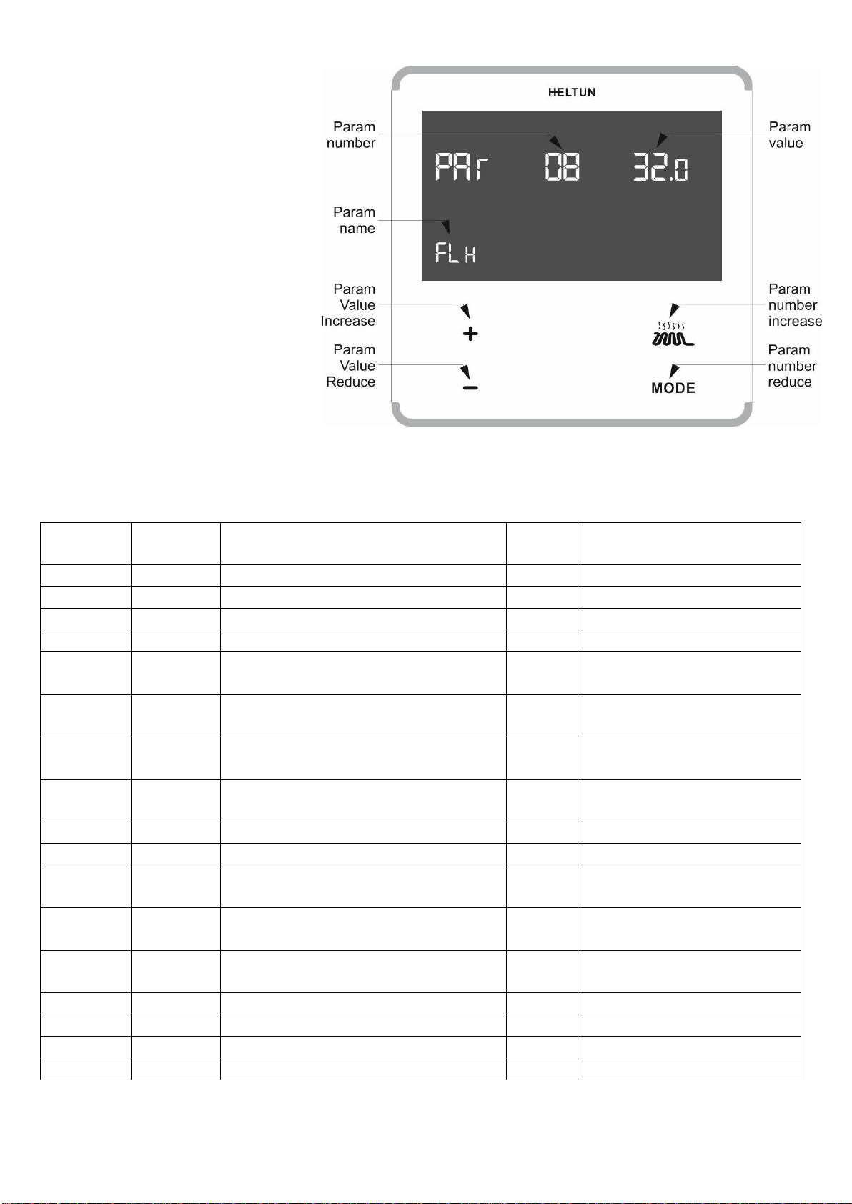
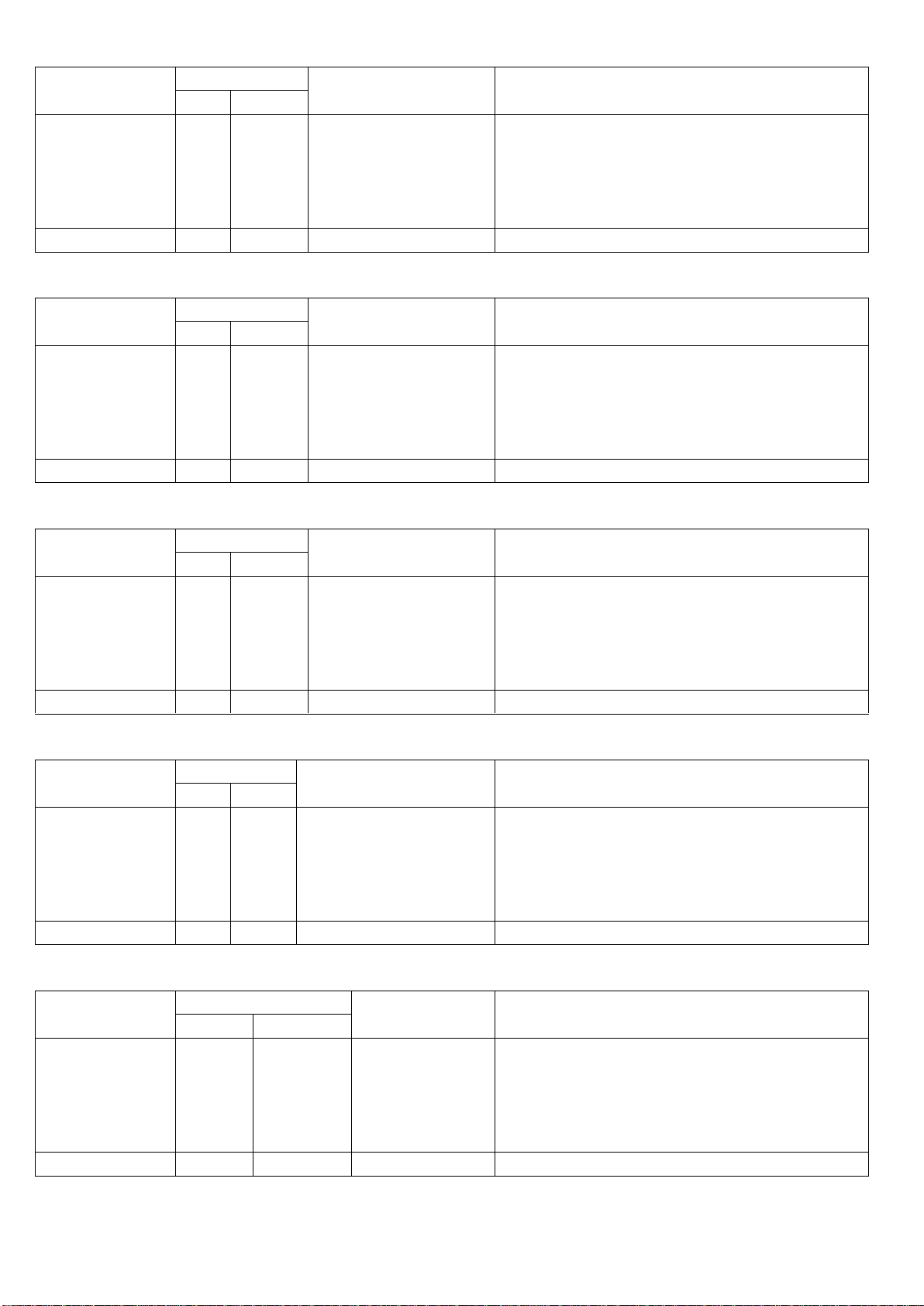
Parameter 01 (dEg) –Degree mode
You can choose Celsius (°C) or Fahrenheit (°F). Floor and air temperature, as well as set point and all
parameters will be indicated in the chosen mode.
Default - Celsius (°C).
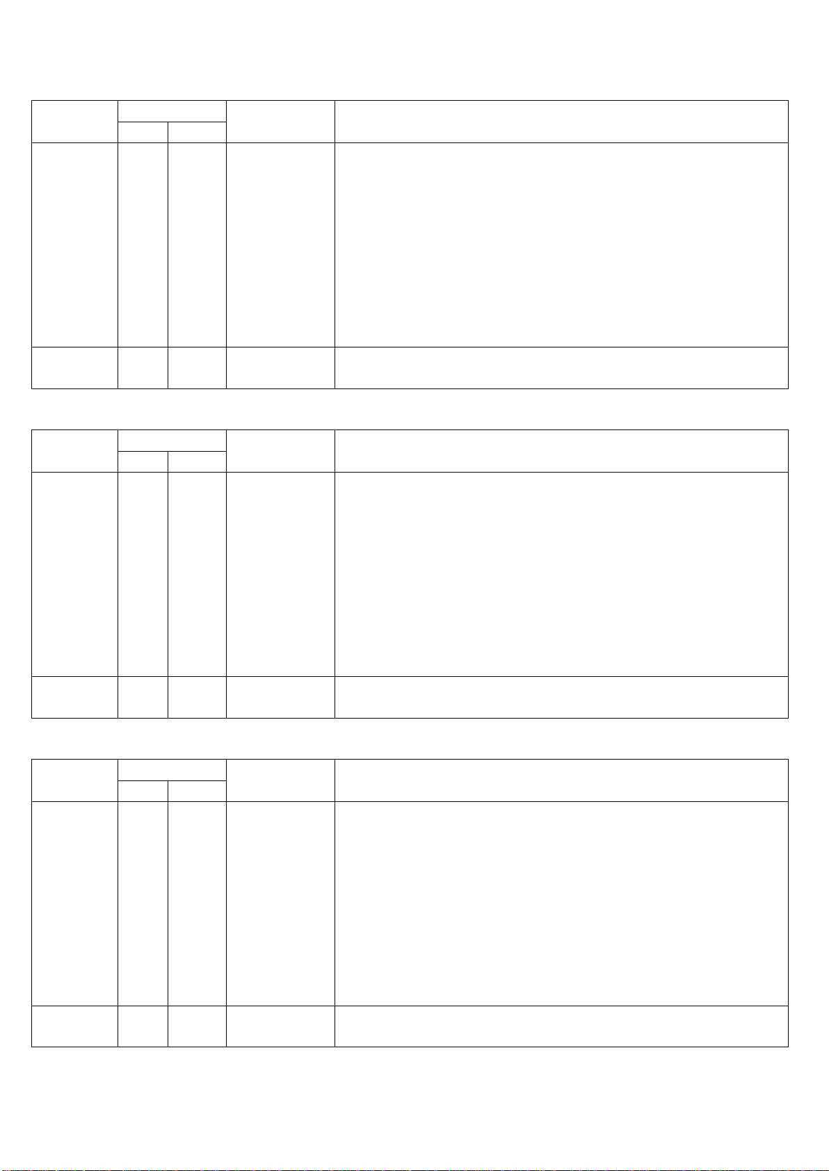
Parameter 02 (Sen) –Source sensor
The thermostat has seven regulation modes based on different sensors values. Use keys “+” and “-” to choose
follow modes:
1) F –Floor sensor
2) FA –Floor sensor + Air sensor
3) A –Air sensor
4) AF –Air sensor + Floor sensor
5) P –Power regulator
6) PF –Power regulator + Floor sensor
7) PA –Power regulator + Air sensor
Thermostat parameters.
1) F –Floor sensor: Parameter is based on the SET POINT reading of the external floor temperature sensor.
2) FA –Floor sensor plus air sensor parameters: Regulation is based on SET POINT applied to the external floor
sensor but also controlled by the internal air temperature sensor ensuring that the room temperature
remains within the set limits. The lower air temperature limit is specified in Param 05 - AIL and the high
temperature limit in Param 06 –AIH.
3) A –Air sensor: Parameter is based on the SET POINT applied to the internal sensor.
4) AF –Air sensor plus floor sensor parameters: Regulation is based on SET POINT applied to the internal room
temperature sensor but also controlled by the floor temperature sensor ensuring that the floor temperature
remains within the set limits. The lower floor temperature limit is specified in Param 07 - FLL and the high
temperature limit in Param 08 –FLH.
5) Power regulator: Parameter is time settings for heating which will be ON during the time in Param 03 –Pon
and then OFF during the time in Param 04 - Pof.
6) PF –Power regulator + Floor sensor parameters: Parameter is heating time set by Params 03 and 04, but
also controlled by the floor temperature sensor. The lower floor temperature limit is specified in Param 07 -
FLL and the high temperature limit in Param 08 –FLH
7) PA –Power regulator + Air sensor parameters: : Parameter is heating time set by Params 03 and 04, but
also controlled by the air temperature sensor. The lower air temperature limit is specified in Param 05 - AIL
and the high temperature limit in Param 06 –AIH.
For example:
In FA mode the SET POINT is set to 30°C, AIL is set to 24°C and AIH is set to 27°C:
a) If floor temperature is lower than 30°C and the room temperature is lower than 27°C the thermostat
will operate in heating mode.
b) If the floor temperature is higher than 30°C or the room temperature is higher than 27°C then the
thermostat will go to IDLE mode which switches off the heater.
c) If the room temperature is lower than 24°C the thermostat will operate in heating mode even
though the floor temperature is higher than 30°C.
Attention: Be careful when setting the lower limitation (Param 05 - AIL and Param 07 –FLL) to be sure that the
value is not too high and it can be reached. Otherwise the thermostat will always operate in the heating
mode.
Note: For safety reasons the thermostat will go to the IDLE mode if the floor temperature reaches 40°C
despite the parameter settings.
Note: If there is no floor sensor installed or it becomes damaged (indicated by ”- - “ in the “FLOOR TEMP”) the
regulation mode (A) will be automatically selected as the source sensor. This can only be changed to (P) or
(PA). Regulation modes (F), (FA), (AF) and (PF) will not be able to be selected.

Parameter 03 (Pon) –Power regulator ON time
This parameter defines floor heating time in minutes when Power Regulator (P, PA or PF) is selected as the
source sensor.
Factory default value is 15 minutes.
Parameter 04 (Pof) –Power regulator OFF time
Floor idle time in minutes when Power Regulator (P, PA or PF) is selected as the source sensor.
Factory default value is 15 minutes.
Parameter 05 (AIL) –Air Temperature Minimum
Room temperature low limit. Reading of internal temperature sensor. It has effect only if FA or PA is selected
as the source sensor.
Factory default value is 21°C or 70°F.
*Note: AIL value cannot be higher than AIH value - 1°C
Parameter 06 (AIH) –Air Temperature Maximum
Room temperature high limit. Reading of the internal temperature sensor. It has effect only if FA or PA is
selected as the source sensor.
Factory default value is 27°C or 81°F.
*Note: AIH value cannot be lower than AIL value + 1°C
Parameter 07 (FLL) –Floor Temperature Minimum
Floor temperature low limit. Reading of external floor temperature sensor. It has effect only if AF or PF are
selected as the source sensor.
Factory default value is 18°C or 64°F.
*Note: FLL value cannot be higher than FLH value - 1°C
Parameter 08 (FLH) –Floor Temperature Maximum
Floor temperature high limit. Reading of the external floor temperature sensor. It has effect only if AF or PF
are selected as the source sensor.
Factory default value is 32°C or 90°F.
*Note: FLH value cannot be lower than FLL value + 1°C
Parameter 09 (dry) –Dry Time
This parameter specifies how long in minutes the thermostat will be in heating mode when the DRY mode is
selected. After this time the thermostat will go to the GEN mode. The time range is 5-90 minutes.
Factory default time is 30 minutes.
Parameter 10 (FSr) –Floor sensor resistance
If the external floor NTC temperature sensor is used it is necessary to select the correct ohm value (resistance)
of the sensor. 9 –100 kΩ is available to select.
In the box is included one floor NTC 10kΩ temperature sensor with three metre connection wire.
The factory default value is 10kΩ.
Note: If the floor sensor is disconnected or damaged “- -” will indicate on the display FLOOR TEMP field and
regulation modes F, FA, AF, PF will be not able to be selected.
Parameter 11 (FCA) –Floor Temperature Calibration
This parameter defines the offset value for floor temperature. Should the external floor temperature sensor
not be correctly calibrated then temperature changes are able to be adjusted by up to +/- 9.5°C or +/- 19°F.
This value will be added or subtracted from the floor temperature sensor reading.
Default value is 0.

Room Temperature Calibration (ACA) –Parameter 12
This parameter defines the offset value for room air temperature. If the internal air temperature sensor is not
correctly calibrated changes of temperature can be made by adjusting the values by up to +/- 9.5°C or +/-
19°F. This value will be added or subtracted from the internal air temperature sensor reading.
Default value is 0.
HYSTERESIS (HYS) –Parameter 13
This parameter defines the hysteresis value for temperature control. The thermostat will stabilize the
temperature with selected hysteresis. For example, if the SET POINT is set for 25°C and HYSTERESIS is set for
0.5°C then the thermostat will change the state to HEATING if the temperature will be lower than 24.5°C and
it will change the state to idle if temperature reaches 25.5°C.
You can change the hysteresis from 0.5°C up to a maximum of 9.5°C in Celsius mode and from 1°F to 19°F in
Fahrenheit mode.
Default values are 0.5°C or 1°F.
DISPLAY BRIGHTNESS
The thermostat has two states of brightness.
Active state –when you press any key and commence adjustments.
Inactive state –after five seconds of inactivity it will revert to inactive state.
The display brightness in either state can be adjusted.
Parameter 14 (brH) –Display brightness high level
You can select the brightness level in the active state from values 1 to 4.
Default value is 3.
Parameter 15 (brL) –Display brightness low level
This parameter defines the brightness level of the display in the inactive state. You can select the level from
values 1 to 4 but the level cannot be higher than the level of brightness for the active state.
Default value is 2.
Parameter 16 (nEt) –INCLUSION / EXCLUSION MODE
If the thermostat is included in the z-wave network the antenna will indicated in the main display and Inc will
be indicated in the Param 16 value. If the thermostat is not included in the network, no antenna will be
indicated in the main display and the Param 16 value will be ECL.
To include or exclude the thermostat into/from your home automation gateway, activate inclusion or
exclusion mode on your gateway then press “+” key on the thermostat for inclusion and the “-” key for
exclusion.
For more details go to point “Z-Wave Functions” – “Network “of this manual on page 9.
Parameter 17 (Prr) –Power Meter Reset
The Heltun thermostat monitors the load and power consumption. The data of total consumption in kWh is
indicated in the Param 17 value. If the device is included in the Z-Wave network it will also send the data of
the current load and total consumption to the main controller.
The thermostat, even when the electricity is disconnected, maintains the electric consumption record in its
memory. To reset the consumption memory press and hold “+” key until the parameter value will be changed
to 0 (about 3 seconds).
CHILD LOCK –LOC
To activate the child lock mode, press and hold the “HEATING” key for 5 seconds. The LOC text will appear in
the bottom left hand corner. To deactivate the child lock press the FLOOR key for 5 seconds and the “UnL” will
appear in the display.

FACTORY RESET –RES
By pressing and holding the “MODE”key for 6 seconds, the thermostat will enter the Factory Reset mode and
“Res” will appear in left bottom corner, “y” in left top corner and “n” in top right corner. Press “+” key if you
want to revert to factory reset or the “HEATING” key to cancel. The factory reset will change all the
parameters to the original factory defaults and will also exclude from the Z-Wave network.
Note: After 3 seconds it will enter the setting mode BUT if the “HEATING” key is not released in a further 3
seconds it will revert to factory reset mode.
Z-WAVE NETWORK
Inclusion
To include the thermostat in the Z-Wave network
1. Go to the “SETTINGS” mode by pressing and holding the “MODE” key for 3 seconds
2. Go to “Par 16 – NET” of the menu by using the “HEATING” key for scrolling up and the “MODE” key for
scrolling down.
3. In the value position you will see the current state of the network. It should be ECL. If Inc is indicated, an
exclusion must be first performed.
4. To start the inclusion mode from the gateway
5. Press “PLUS” key to start inclusion process
6. Lines will be moving in value position.
7. The “Inc” should appear in the value position if the inclusion has been successful.
8. Should “Err” appear in the value position then the inclusion was not completed.
Note: In case the device has been part of a system before and not excluded since, inclusion is not possible. In
this case, exclusion must be performed before inclusion.
Exclusion
To exclude the thermostat from the Z-Wave network
1. Go to “SETTINGS” mode by pressing and holding the “MODE” key for 3 seconds
2. Go to “Par 16 – NET” of the menu using the keys “HEATING” for scrolling up and “MODE” for scrolling
down.
3. In the value position the current state of network state will be displayed. It should be Inc. If ECL is indicated
then the device is already excluded.
4. To commence the exclusion from the gateway.
5. Press the “MINUS” key to start the exclusion process
6. Lines will be moving in the value position.
7. The “Ecl” should appear with successful deletion.
8. If the “Err” should appear then start again.
If the thermostat is included in the network then in the bottom right corner of the main screen the antenna
icon will be displayed with connection lines . If not on the network then it will be displayed without lines.
Association
Association enables the thermostat to control other Z-Wave products from the network including relays etc.
Up to ten other products from different manufacturers can be within the association grouping.
Parameters configuration using gateway
All configuration parameters are accessed through COMMAND_CLASS_CONFIGURATION

1 –Degree Mode
Value
Description
How to Read and Write
Dec
Hex
Available
settings
0
1
0x00
0x01
°C – Celsius
°F –Fahrenheit
Read: Command = CONFIGURATION_GET
Parameter Number = 1 (0x01)
Report is returned.
Write: Command = CONFIGURATION_SET
Parameter Number = 1 (0x01)
Default settings
0
0x00
°C
Parameter size: 1 byte
2 –Source Sensor
Value
Description
How to Read and Write
Dec
Hex
Available
settings
0
1
2
3
4
5
6
0x00
0x01
0x02
0x03
0x04
0x05
0x06
F –Floor sensor
FA –Floor+Air sensors
A –Air sensor
AF –Air+Floor sensors
P –Time regulation
PF –Time+Floor sensor
PA –Time+Air sensor
Read: Command = CONFIGURATION_GET
Parameter Number = 2 (0x02)
Report is returned.
Write: Command = CONFIGURATION_SET
Parameter Number = 2 (0x02)
Default settings
0
0x00
F
Parameter size: 1 byte
3 –Power Regulation ON time
Value
Description
How to Read and Write
Dec
Hex
Available
settings
10
-
90
0x0A
-
0x5A
Minutes
Read: Command = CONFIGURATION_GET
Parameter Number = 3 (0x03)
Report is returned.
Write: Command = CONFIGURATION_SET
Parameter Number = 3 (0x03)
Default settings
15
0x0F
15 min
Parameter size: 1 byte
4 –Power Regulation OFF time
Value
Description
How to Read and Write
Dec
Hex
Available
settings
10
-
90
0x0A
-
0x5A
Minutes
Read: Command = CONFIGURATION_GET
Parameter Number = 4 (0x04)
Report is returned.
Write: Command = CONFIGURATION_SET
Parameter Number = 4 (0x04)
Default settings
15
0x0F
15 min
Parameter size: 1 byte
5 –Air Temperature Minimum
Value
Description
How to Read and Write
Dec
Hex
Available
settings
40
-
360
0x28
-
0x0168
(Value/10),
Temperature in
Celsius
Read: Command = CONFIGURATION_GET
Parameter Number = 5 (0x05)
Report is returned.
Write: Command = CONFIGURATION_SET
Parameter Number = 5 (0x05)
Default settings
210
0xD2
21.0°C
Parameter size: 2 byte

6 –Air Temperature Maximum
Value
Description
How to Read and Write
Dec
Hex
Available
settings
50
-
370
0x32
-
0x0172
(Value/10),
Temperature in
Celsius
Read: Command = CONFIGURATION_GET
Parameter Number = 6 (0x06)
Report is returned.
Write: Command = CONFIGURATION_SET
Parameter Number = 6 (0x06)
Default settings
270
0x010E
27.0°C
Parameter size: 2 byte
7 –Floor Temperature Minimum
Value
Description
How to Read and Write
Dec
Hex
Available
settings
40
-
360
0x28
-
0x0168
(Value/10),
Temperature in
Celsius
Read: Command = CONFIGURATION_GET
Parameter Number = 7 (0x07)
Report is returned.
Write: Command = CONFIGURATION_SET
Parameter Number = 7 (0x07)
Default settings
180
0xB4
18.0°C
Parameter size: 2 byte
8 –Floor Temperature Maximum
Value
Description
How to Read and Write
Dec
Hex
Available
settings
50
-
370
0x32
-
0x0172
(Value/10),
Temperature in
Celsius
Read: Command = CONFIGURATION_GET
Parameter Number = 8 (0x08)
Report is returned.
Write: Command = CONFIGURATION_SET
Parameter Number = 8 (0x08)
Default settings
320
0x0140
32.0°C
Parameter size: 2 byte
9 –Dry Time
Value
Description
How to Read and Write
Dec
Hex
Available
settings
5
-
90
0x05
-
0x5A
Time in minutes
Read: Command = CONFIGURATION_GET
Parameter Number = 9 (0x09)
Report is returned.
Write: Command = CONFIGURATION_SET
Parameter Number = 9 (0x09)
Default settings
30
0x1E
30 min
Parameter size: 1 byte
10 –Floor Sensor Resistance
Value
Description
How to Read and Write
Dec
Hex
Available
settings
10000
-
100000
0x03E8
-
0x0186A0
Resistance in
Ohm (Ω)
Read: Command = CONFIGURATION_GET
Parameter Number = 10 (0x0A)
Report is returned.
Write: Command = CONFIGURATION_SET
Parameter Number = 10 (0x0A)
Default settings
10000
0x2710
10kΩ
Parameter size: 4 byte

11 –Floor Temperature Calibration
Value
Description
How to Read and Write
Dec
Hex
Available
settings
-95
-
95
0xFFA1
-
0x5F
(Value/10) in Celsius
-9.5°C to +9.5°C
Read: Command = CONFIGURATION_GET
Parameter Number = 11 (0x0B)
Report is returned.
Write: Command = CONFIGURATION_SET
Parameter Number = 11 (0x0B)
Default settings
0
0x00
0°C
Parameter size: 2 byte
12 –Air Temperature Calibration
Value
Description
How to Read and Write
Dec
Hex
Available
settings
-95
-
95
0xFFA1
-
0x5F
(Value/10) in Celsius
-9.5°C to +9.5°C
Read: Command = CONFIGURATION_GET
Parameter Number = 12 (0x0C)
Report is returned.
Write: Command = CONFIGURATION_SET
Parameter Number = 12 (0x0C)
Default settings
0
0x00
0°C
Parameter size: 2 byte
13 –Temperature Hysteresis
Value
Description
How to Read and Write
Dec
Hex
Available
settings
5
-
95
0x5
-
0x5F
(Value/10) in Celsius
0.5°C to 9.5°C
Read: Command = CONFIGURATION_GET
Parameter Number = 13 (0x0D)
Report is returned.
Write: Command = CONFIGURATION_SET
Parameter Number = 13 (0x0D)
Default settings
5
0x05
0.5°C
Parameter size: 1 byte
14 –Active display brightness level
Value
Description
How to Read and Write
Dec
Hex
Available
settings
1
2
3
4
0x01
0x02
0x03
0x04
1 –Lowest level
4 –Highest level
Read: Command = CONFIGURATION_GET
Parameter Number = 14 (0x0E)
Report is returned.
Write: Command = CONFIGURATION_SET
Parameter Number = 14 (0x0E)
Default settings
3
0x03
Level 3
Parameter size: 1 byte
15 –Inactive display brightness level
Value
Description
How to Read and Write
Dec
Hex
Available
settings
1
2
3
0x01
0x02
0x03
1 –Lowest level
3 –Highest level
Read: Command = CONFIGURATION_GET
Parameter Number = 15 (0x0F)
Report is returned.
Write: Command = CONFIGURATION_SET
Parameter Number = 15 (0x0F)
Default settings
2
0x02
Level 2
Parameter size: 1 byte

FUNCTIONAL PARAMETERS
1 –Setpoint Temperature in GEN mode
Value
Description
How to Read and Write
Dec
Hex
Available
settings
40
-
370
0x28
-
0x0172
Temperature
setpoint used
in GEN mode.
(Value/10) in
Celsius.
4.0°C to
37.0°C
Read:
Command Class = COMMAND_CLASS_THERMOSTAT_SETPOINT
Command = THERMOSTAT_SETPOINT_GET
Type=Heating(0x01)
Report is returned.
Write:
Command Class = COMMAND_CLASS_THERMOSTAT_SETPOINT
Command = THERMOSTAT_SETPOINT_SET
Type=Heating(0x01)
Default
settings
250
0xFA
25.0°C
2 –Setpoint Temperature in DRY mode
Value
Description
How to Read and Write
Dec
Hex
Available
settings
40
-
370
0x28
-
0x0172
Temperature
setpoint used
in DRY mode.
(Value/10) in
Celsius.
4.0°C to
37.0°C
Read:
Command Class = COMMAND_CLASS_THERMOSTAT_SETPOINT
Command = THERMOSTAT_SETPOINT_GET
Type=Dry air(0x08)
Report is returned.
Write:
Command Class = COMMAND_CLASS_THERMOSTAT_SETPOINT
Command = THERMOSTAT_SETPOINT_SET
Type=Dry air(0x08)
Default
settings
300
0x012C
30.0°C
3 –Setpoint Temperature in ECO mode
Value
Description
How to Read and Write
Dec
Hex
Available
settings
40
-
370
0x28
-
0x0172
Temperature
setpoint used
in ECO mode.
(Value/10) in
Celsius.
4.0°C to
37.0°C
Read:
Command Class = COMMAND_CLASS_THERMOSTAT_SETPOINT
Command = THERMOSTAT_SETPOINT_GET
Type=Energy save heating(0x0B)
Report is returned.
Write:
Command Class = COMMAND_CLASS_THERMOSTAT_SETPOINT
Command = THERMOSTAT_SETPOINT_SET
Type=Energy save heating(0x0B)
Default
settings
180
0xB4
18.0°C

4 –Thermostat operation mode
Value
Description
How to Read and Write
Dec
Hex
Available
settings
0
1
8
11
0x00
0x01
0x08
0x0B
OFF
GEN
DRY
ECO
Read:
Command Class = COMMAND_CLASS_THERMOSTAT_MODE
Command = THERMOSTAT_MODE_GET
Report is returned.
Write:
Command Class = COMMAND_CLASS_THERMOSTAT_MODE
Command = THERMOSTAT_MODE_SET
Supported modes: Off (0x00), heating (0x01), dry air (0x08),
energy save heating (0x0B).
Default
settings
1
0x01
GEN
Table of contents
Other Heltun Thermostat manuals

Heltun
Heltun HE-HT01 User manual

Heltun
Heltun HE-FT01 User manual

Heltun
Heltun HE-HT01 User manual

Heltun
Heltun HE-FT01 User manual

Heltun
Heltun HE-FT01 User manual

Heltun
Heltun HE-ZW-THERM-FC1 User manual

Heltun
Heltun HE-HT01 User manual

Heltun
Heltun HE-ZW-THERM-FL2 User manual

Heltun
Heltun HE-HT01 User manual