Heltun HE-HT01 User manual

HEATING THERMOSTAT HE-HT01
USER MANUAL V1.0

Table of Contents
!
"!
#$!
%#&%'#$()*+
#,&$#$(-%.*+
/0& .#$+
,%&,. .#$1
2-%&2#$(- *1
#-3&#%#$(4*1
%$56(5%*1
/(/,*1
7.#1
"58
%.9:
%.99
%.9;
<.9
9
"$,. %9
)$29
=&>369
-$$.=&>69
/.'=&>69
9
9
-?$9
-9!
=&>"2;9!
7.?.=&>"(@ *9!
$'9+
> (;&0*98
;

Overview
This is the user manual for HELTUN HE-HT01 Advanced Programmable Thermostat for Heating S stems.
The HE-HT01 can be flush mounted over standard electrical junction boxes. It is designed to maintain a constant room
temperature b providing sensors for both ambient and radiant floor heating s stems. It is recommended for control of
electric heating s stems (radiator, convection, electric fireplace), boilers, or electric underfloor heating. Heating
elements are directl controlled b a single-pole switch. The maximum load for the HE-HT01 thermostat is 16 Amps
(4000W @ 250VAC) which must be connected through a circuit breaker.
The HE-HT01 has an LCD screen, six sensitive capacitive touch control buttons, and two temperature sensors (for
ambient air temperature and an external NTC floor sensor). It is also equipped with built-in sensors for humidit ,
illumination, and energ consumption.
The HE-HT01 integrates a Z-Wave 700 platform module allowing it to be used with Z-Wave home automation s stems.
The HE-HT01 supports Z-Wave ‘S0’ and ‘S2’ securit protocols, SmartStart technolog , and can be connected
(“associated”) to ten other Z-Wave devices, such as rela s, switchers, etc.
You can select one of six operation modes either manuall , or b using a Z-Wave controller/gatewa . As a safet
measure, the HE-HT01 protects radiant floor s stems from overheating b automaticall switching off if the
temperature reaches 40°C.
The displa has a user-friendl interface, showing: ambient air temperature, floor temperature, user set point, humidit
level, current operating mode, time, da of the week, and status of the Z-Wave network and rela . Displa brightness
adjusts to ambient light conditions automaticall making it alwa s eas to read.
Technical Specifica ions
Front frame (on wall) dimensions: 89mm (H) х 89mm (W) х 9mm (D)
Rear electronics package dimensions: 53mm (H) х 53mm (W) х 28mm (D)
Materials: Tempered glass displa /bod , Flame retardant plastic
5 frame colors: White, Gloss Black, Matte Black, Silver, Chrome
6 glass colors: White, Black, Yellow, Green, Red, Blue
LCD: 73mm x 42mm (3.3 inch), black with white segments
6 capacitive-touch buttons
Operating temperature: 0°С to +50°С
Power suppl : 85-265VAC 50Hz/60Hz, 24-48VDC
Power consumption: 1W
Maximum resistive load: 16А, 4000W @ 250VAC
Rela switching with zero-cross technolog
Rela life time: 100.000 switches
Internal ambient light sensor
Internal temperature sensor
oMeasurement range: –30°C to +80°C
oAccurac : ±0.5°C
Internal humidit sensor
oMeasurement range: 0% to 80%RH
oAccurac : ±3.0%RH
External floor temperature sensor
oNTC 10kΩ
oMeasurement range: -30°C to +80°C
oAccurac : ±0.5°C
Energ consumption meter
IP class: IP21
Z-Wave Plus V2 SDK: V7.11
Z-Wave module: ZGM130S
Requires mounting to flush electrical junction box:
round or square t pe – min. depth 40mm

Func ions & Fea ures
Options for Inclusion/Exclusion to/from Z-Wave network
oNon-Secure
oS0 Secure
oS2 Unauthorized, S2 Authorized with Ke
Association control with 10 devices from network
6 operational modes with individual temperature set points:
oCOM – Comfort/Heating Mode
oECO – Energ saving Mode
oVAC – Vacation/Awa Mode
oDRY – Floor Dr Mode
oTIME – Schedule Mode
oMANUAL – Manual Control Mode
4 time schedules for 7 da s of the week:
oMorning
oDa
oEvening
oNight
Temperature sensor selection:
oFloor temperature onl
oAir temperature onl
oFloor + Air temperature
oPower regulator (Automatic ON/OFF timer)
Can be used with different NTC-sensors (range: 1kΩ to 100kΩ)
Periodic measurements from:
oInternal temperature sensor
oExternal floor temperature sensor
oInternal humidit sensor
oInternal ambient light sensor
oEnerg consumption meter
Calibration of Internal Room Air Temperature Sensor
Calibration of External NTC Temperature Sensor
Temperature set intervals: 4.0°C to 37.0°C
Temperature limiter: 40.0°C
Zero-cross rela switching
Temperature h steresis selection range: 0.2°C to 10.0°C
Temperature format: Celsius (°C) or Fahrenheit (°F)
Time mode format: 24 or 12 hours (AM/PM)
LCD brightness:
oAutomatic adjustment (depending on ambient light)
oManual adjustment (15 levels).
LCD standb mode (different brightness for active and inactive states)
LCD backlight blinking function (for eas identification among other Z-Wave devices)
Child lock mode (touch buttons lockout mode)
Real-time and cumulative energ usage to 0.1kW accurac
Factor reset function
SmartStart technolog for quick addition to Z-Wave networks
Encr pted OTA (Over The Air) firmware update feature

Ins alla ion
HELTUN recommends the HE-HT01 thermostat be installed b a licensed electrician in a
manner that conforms to local regulations and building codes. Provide these instructions to the
licensed electrician who is installing the HE-HT01.
WARNING: Elec rical power mus be swi ched off during ins alla ion.
1. Placement of the HE-HT01 is of utmost importance for proper operation and must be awa
from sunlight and sources of direct heat. We recommend installing the HE-HT01
approximatel 1.5 meters above the floor.
2. Remove the displa unit and backplate of the HE-HT01 from the packaging.
3. FIRST ENSURE THE POWER IS OFF at the main circuit breaker, and then test the wires
with a probe or multimeter to verif . Insert the power and heater wires to the correct HE-HT01
terminals b inserting a small Phillips-head screwdriver in the slot beneath each terminal to
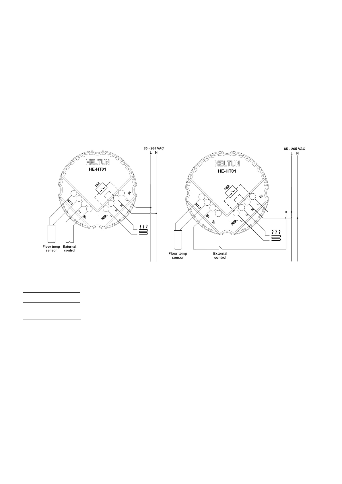
open. Follow the connection diagram and instructions below:
• Power wires: connect Line & Neutral wires to L & N terminals labeled “IN”
• Hea er wires: connect Line & Neutral wires to L & N terminals labeled with “heating
element” graphic
Connection diagram 1 Connection diagram 2
4. If using the HE-HT01 for radiant floor heating, connect the NTC temperature
sensor wire to the terminals labeled “NTC.” A 10 kΩ NTC sensor is included
inside the HE-HT01 packaging, but an NTC sensor can be used.
No e: If an NTC sensor other than 10 kΩ is used, ou must change the
sensor Parameter value in the settings menu (Parameter 01 - FSr) – see
“Settings Menu” section below.
5. If ou will be using an external device to select modes for the HE-HT01
(such as a securit s stem), connect wires from the external device’s dr
contacts to the two HE-HT01 terminals labeled “EXT.”
6. Making sure the HE-HT01 backplate is oriented on the wall with the word
“TOP” pointed upwards, secure the backplate onto the electrical junction box
using the four provided screws (do not overtighten). Once the backplate is
secured onto the wall, assemble the HE-HT01 displa unit onto the
backplate b first carefull aligning the two top snap connectors, and then
gentl pushing the entire displa unit until it ‘snaps’ into position all the wa
around.
7. Next, switch On the main power at the circuit breaker (see photo above).
The HE-HT01 will start up showing the original default factor settings.
8. Remove the clear protective film from the displa unit b pulling on the top
right-hand tab.

Disassembly
1. To disassemble, ENSURE POWER IS SWITCHED OFF at the main circuit breaker AND THE LCD SCREEN IS
BLANK.
2. To remove the HE-HT01 displa unit grasp firml at the bottom and pull backwards while tilting outwards until all
tabs disconnect.
3. Remove screws from backplate and disconnect the wires b inserting a small Phillips-head screwdriver into the slot
beneath each wire to release.
Touch Panel Opera ion
The touch panel has six capacitive-touch buttons which require minimal pressure to operate.
Symbol: Name:
Plus
Minus
Time
Settings
Manual Heating
Mode
Function:
Increase Set Point Temperature
Decrease Set Point Temperature
Change Schedule
Open Parameters Menu
Manuall Switch Heating Element On or Off
Change the Operational Mode: (COM, TIME, DRY, ECO, VAC, MAN)
The Plus “+” button will increase Set Point temperature b 0.5°C (or 1°F) with each touch. The Minus “–“ button will
decrease Set Point temperature b the same 0.5°C (or 1°F). The Set Point temperature is displa ed in the bottom left
corner of the LCD displa under “SET TEMP.”
No e: The minimum Set Point is 4.0°C (or 39°F) and the maximum Set Point is 37.0°C (or 99°F).
The HE-HT01 has two working modes: HEATING (switched On) and IDLE (switched Off). In HEATING mode, the
heating element icon ( ) will appear near the right bottom corner of the displa (to the left of the connectivit icon).
The heating element icon will disappear when the HE-HT01 is in IDLE mode.
Opera ion Modes
The current Operating Mode is shown on the middle, right of the LCD displa under the label: “HEATING MODE.”
The HE-HT01 has 6 Operating Modes:
COM – Comfort Mode (heating)
TIME – Time Mode (schedule different Set Point per time and da )
DRY – Floor Dr ing Mode
ECO – Econom (power efficient / energ saving) Mode
VAC – Vacation Mode (i.e. ‘Awa ’ Mode)
MAN – Manual Mode
!
Change Modes b touching the MODE button (bottom right of displa unit) until the desired Mode is reached. Each
operating mode has individual temperature Set Points. The HE-HT01 will operate automaticall depending on the
current Set Point indicated under the SET TEMP label. To change the Set Point value, choose the desired mode and
press Plus “+” button to increase, or Minus “–” button to decrease. You ma alternativel control Set Points through
our Z-Wave gatewa software.
COM - Comfor Mode (Hea )
This mode is recommended for normal comfort. The factor default set point is 25.0°C (77°F).
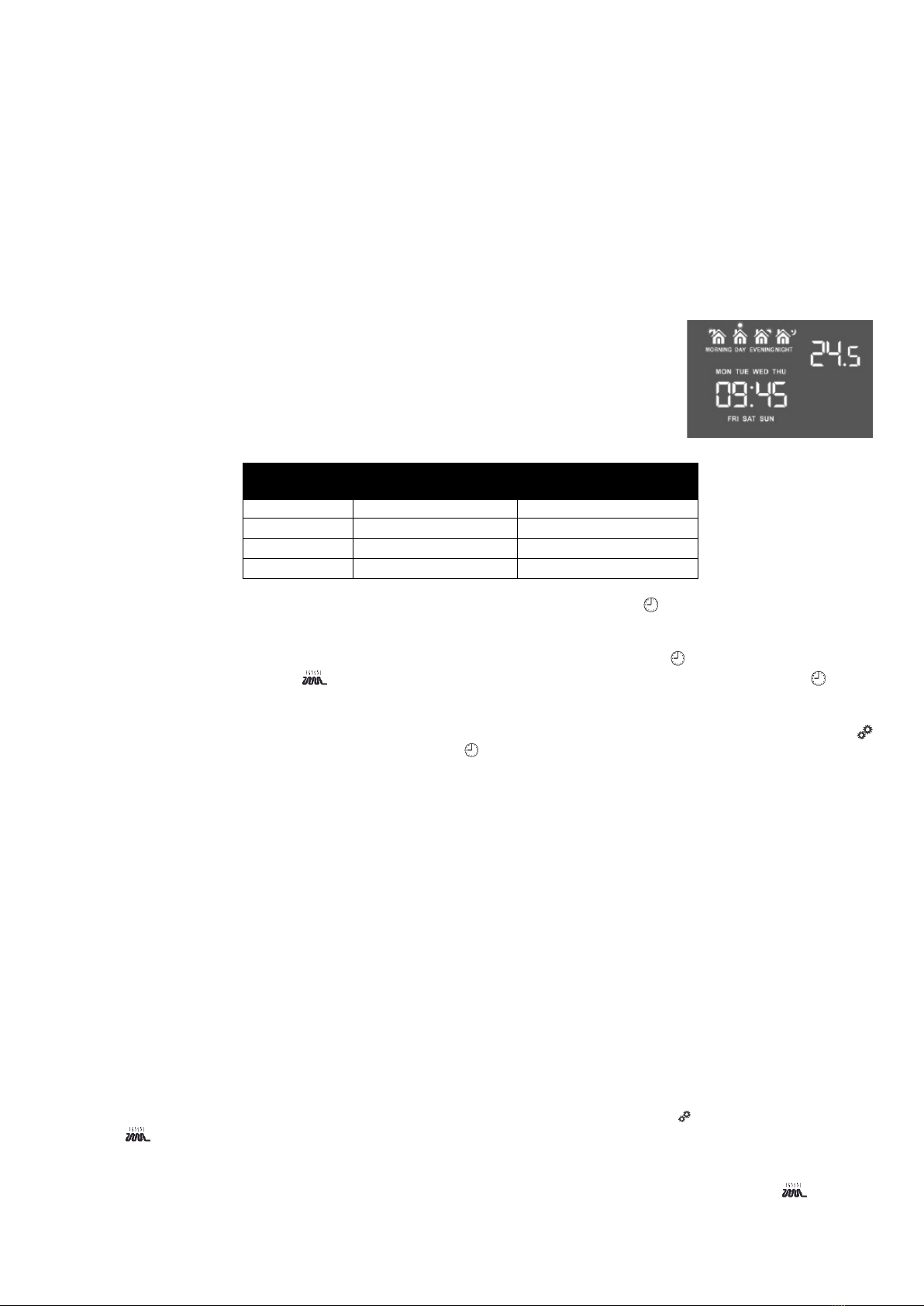
TIME - Tempera ure Schedule Mode (Au o Changeover)
The Temperature Schedule (TIME) Mode can adjust home temperatures automaticall to align with our personal
habits, saving energ while ou are awa , and maintaining a comfortable temperature while ou are active at home.
The HE-HT01 can have different Schedules for Morning, Da time, Evening and Night.
For example, the “Morning” Schedule could be set to 25.0°C (77°F) starting at 7:00. The
“Da ” Schedule could then be set to 11.0°C (or 52°F) at 9:00 when ever one has gone to
work or school, and so on. Here are recommended Scheduled Set Points for heating
during the work week – ou ma wish to change these on weekends depending on our
famil ’s schedule (see example below):
Schedule
Mode
Set
Time
Set Point
Temperature
Morning 6:00 (6:00am) 24°C (75°F)
Day 9:00 (9:00am) 20°C (68°F)
Evening 18:00 (6:00pm) 23°C (73°F)
Nigh 23:00 (11:00pm) 18°C (64°F)
To set up the time and temperature for each Schedule press and hold the Clock “ ” button for three seconds. The
displa will change to the Time menu.
To set up the start time for each Schedule, choose the Schedule b pressing the Clock “ ” button then adjust the time
b pressing the Heating Element “ ” button to increase, or “MODE” button to decrease. Press the Clock “ ” button
again to advance to the next schedule and set the time for all four: Morning, Da , Evening & Night.
To choose the temperature Set Points for each Schedule, choose the da of the week b pressing the Gear “ ”
button, then choose the Schedule b pressing the Clock “ ” button and adjust the temperature Set Point up or down
b pressing the Plus “+” or Minus “–“ buttons. Do this action for each da of the week.
No e: All four Schedules (Morning, Da , Evening, & Night) are the same for all seven da s of the week.
No e: TIME mode will onl work properl if the correct current time and date have been set. The time can be
automaticall corrected from our Z-Wave gatewa if the Parameter 9 value is set to 1. Or it can be set manuall in
Parameters 11, 12, and 13 in the Settings Menu (see below).
No e: When in TIME mode, the temperature Set Point (under the label SET TEMP) will be automaticall changed
depending on the Schedule. At an time, the Set Point can be adjusted up or down manuall but it will be effective onl
until the next Schedule.
DRY - Fas Floor Drying Mode
This mode is recommended for use if a high floor temperature is required for a limited period of time. For example,
after washing the floor. B choosing DRY Mode, the HE-HT01 will increase the temperature to the selected Set Point
for the time specified in the “Dr Time” parameter (Parameter 7). A time range of 5 to 90 minutes can be set. As the
Dr Time passes, the HE-HT01 will automaticall change to the Mode set in Parameter 8.
To change the Dr Time Parameter, open the “Settings Menu” b pressing the Gears “ ” button for three seconds.
Use the and MODE buttons to scroll up and down through the menu to Parameter 07. Then use ke s “ +” and “–”
to increase or reduce the Dr Time setting (in minutes).
To choose the mode to revert to after Dr Time has elapsed (while still in the Settings Menu), press the or MODE
button to select Parameter 8, then use ke s “+” and “–” to choose the desired Mode as follows:
+

Mode:
COM
TIME
DRY
ECO
VAC
MAN
Value:
1
2
n/a
4
5
6
Notes:
This is the factor default for revert after DRY Mode (Parameter 8)
You cannot revert to DRY Mode.
If MAN Mode is chosen, the HE-HT01 will select IDLE state
No e: Factor defaults for Dr Time are: 30 minutes at 30.0°C (86°F).
ECO - Energy Saving Mode
This Mode can be used if lower temperature and energ consumption is desired. It can also be used at night or when
awa from all or part of the propert for a length of time. The factor default ECO Set Point is 20.0°C (68°F).
VAC - Vaca ion Mode (Away)
Use Vacation Mode when ou are planning to be awa from home for some period. The factor default temperature
Set Point is 15.0°C (59°F).
No e: The minimum set point for each mode is 4.0°C (39°F) and the maximum set point is 37.0°C (99°F).
MAN - Manual Con rol Mode (Off)
In this Mode the HE-HT01 schedules are disabled and the heating state is switched On & Off manuall b pressing the
Heating Element “ ” button.
No e: When in Manual Control Mode the SET TEMP will indicate “OFF.”
Child Lock (LOC)
The Child Lock feature allows ou to disable the HE-HT01 touch buttons temporaril . To activate the Child Lock Mode,
press and hold the Heating Element ( ) button for five seconds until the Lock Icon ( ) appears in the bottom center
of the displa . To deactivate the Child Lock, press the Heating Element ( ) button until the Lock Icon ( ) disappears.
Fac ory Rese (RES)
B pressing and holding the “MODE” ke for ten seconds, the HE-HT01 will enter Factor Reset Mode, displa ing
“REs” in the left bottom corner, “y” in top left corner and “n” in top right corner. Press the Plus (+) button to revert to
factor settings, or the Heating Element ( ) button to cancel. The factor reset will change all the Parameters to their
original factor default values and will also Exclude the device from an Z-Wave network.
No e: Please use this procedure onl when the network primar controller is missing or otherwise inoperable.
Se ings Menu
To enter the Settings Menu, press and hold the Gear “ ” button for three seconds. The top left corner will displa the
Parameter Number. The bottom left corner will displa the Parameter Name (abbreviated). And the top right corner will
displa the Parameter Value.
1

To scroll through the menu, press the Heating Element “ ” button to go up and the MODE ke to go down.
To change the Parameter value, press the Plus “+” or Minus “–” buttons.
To leave the Settings Menu press and hold the ke for 3 seconds or just wait. If no action is detected for 10 seconds
the displa will automaticall revert to the main displa mode.
Parame er Lis
Group Number Name Descrip ion Defaul
Value Value Range
Inputs
configuration
01 FSr Floor Sensor Resistance, kΩ 10 1…100
02 In 1 EXT input mode 0 0, 1, 2
03 In 2
Mode number for EXT input action:
1 = COM, 2 = TIME, 3 = DRY, 4 = ECO,
5 = VAC, 6 = MAN (On), 7 = MAN (Off)
6 1, 2, 3, 4, 5, 6, 7
04 SEn Source Sensor:
1 = A, 2 = AF, 3 = F, 4 = FA, 5 = P, 6 = PA, 7 = PF 31, 2, 3, 4, 5, 6, 7
Time
configuration
05 POn Power Regulation ON time, min 30 10…240
06 POF Power Regulation OFF time, min 30 10…240
07 dr 1 Dr Time, min 30 5…90
08 dr 2 Mode to revert to after completion of Dr mode:
1 = COM, 2 = TIME, 4 = ECO, 5 = VAC, 6 = MAN (Off) 1 1, 2, 4, 5, 6
09 tCr Time correction b controller 1 0, 1
10 tFo Time Format 0 0, 1
11 dA Da of the Week 1 1, 2, 3, 4, 5, 6, 7
12 tIH Time: Hour 0 0…23
13 tIL Time: Minute 0 0…59
Temperature
configuration
14 AtL Air Temperature Minimum 21 / 69 4.0…36.0 °C
(39…96 °F)
15 AtH Air Temperature Maximum 27 / 80 5.0…37.0 °C
(41…98 °F)
16 FtL Floor Temperature Minimum 18 / 64 4.0…36.0 °C
(39…96 °F)
17 FtH Floor Temperature Maximum 32 / 89 5.0…37.0 °C
(41…98 °F)
18 dEg Temperature Units Selection: 0 = °C, 1 = °F 0 0 = °C, 1 = °F
19 AtC Air Temperature Calibration 0 (-9.5)…9.5 in °C
(-17)…17 in °F
20 FtC Floor Temperature Calibration 0 (-9.5)…9.5 in °C
(-17)…17 in °F
21 H S Temperature H steresis 0.5 / 0.9 0.2…10.0 in °C
0.3…18.0 in °F
Displa
Brightness
22 Abc Displa auto-brightness control 1 0, 1
23 Idb Displa brightness manual control level 10 1…15
Touch
Sensitivit 24 tCH Touch button sensitivit :
5 = Highest sensitivit , 50 = Lowest sensitivit 15 5…50
Energ
Consumption
25 AC AC voltage, Volt Read Onl
26 Prr Energ consumption meter value, kWH Read Onl
27 POr Load Power, Watts Read Onl
Versions 28 Hrd Hardware Version Read Onl
29 APP Application Version Read Onl
Z-Wave
30 bSA Mode selection upon Basic Set Action command:
1=COM, 2=TIME, 3=DRY, 4=ECO, 5=VAC, 6=MAN (On)
1 1, 2, 3, 4, 5, 6
31 nEt Inclusion / Exclusion Mode EcL InC, EcL
32 rEg Frequenc Region EU
EU: Europe
US: USA
AU: Australia
HO: Hong Kong
IN: India
IL: Israel
RU: Russia
CN: China
JP: Japan
OR: Korea
8
Inpu Configura ion
Parame er 01 (“FSr”) – Floor Sensor Resis ance
If the external floor NTC temperature sensor is used it is necessar to select the correct resistance value in Ohms (Ω)
of the sensor. The selection range is 1 to 100 kiloOhms (kΩ). One 10kΩ NTC floor temperature sensor is included in
the HE-HT01 package with a 3-meter connection wire. The factor default value is 10kΩ.
No e: If the floor sensor is disconnected or damaged “—” will be shown on the LCD displa under the FLOOR TEMP
label.
Parame er 02 (“In 1”) – S1 Inpu Mode
The HE-HT01 can be connected to the dr output contacts of an external device (i.e. securit s stem) to control the
Thermostat operating modes depending on the state of the external device through.
Two different connection diagrams are possible.
No e: In case of using “S1 connection diagram 2”, it is MANDATORY to connect S1 terminal to the same wire
connected to terminal L on the device (labeled as “IN”) through dr contacts of an external device (like wall switch).
S1 connection diagram 1 S1 connection diagram 2
If Parameter value = 0 no action will be taken (the input state is ignored b the Thermostat logic).
If Parameter value = 1 the Thermostat will be switched to the operating mode selected in Parameter 3 if the output was
short-circuited. The Heating Thermostat will go back to previous mode as soon as the input is open.
I f Parameter value = 2 the HE-HT01 will be switched to the operating mode selected in Parameter 3 if the output was
short-circuited, but it will not undertake an action if the input is open again.
No e: The Mode switch is blocked when the Source Sensor (Parameter 4) is: P (value = 5), PA (value = 6) or PF
(value = 7). Factor default value is 0.
Parame er 03 (“In 2”) – Opera ing Mode For S1 Inpu Ac ion
This Parameter allows selection of which Operating Mode the HE-HT01 should revert to if the external input is short-
circuited. 1 = COM, 2 = TIME, 3 = DRY, 4 = ECO, 5 = VAC, 6 = MAN mode with IDLE (Off) state, 7 = MAN mode with
HEATING (On) state. Factor default value is 6.
Parame er 04 (“SEn”) – Source Sensor
The HE-HT01 has seven Regulation Modes based on different sensors values. Use the Plus “+” and Minus “–” buttons
to choose follow modes:
1) A – Air sensor
2) AF – Air sensor + Floor sensor
3) F – Floor sensor
4) FA – Floor sensor + Air sensor
5) P – Power regulator
6) PA – Power regulator + Air sensor
7) PF – Power regulator + Floor sensor
9:

1) A – Air sensor: Regulation (heating control) is based on the SET POINT applied to the internal room air temperature
sensor.
2) AF – Air sensor plus floor sensor: Regulation is based on SET POINT applied to the internal room temperature
sensor but also controlled b the floor temperature sensor ensuring that the floor temperature remains within the set
limits. The lower floor temperature limit is specified in Parameter 16 (FtL) and the high temperature limit in parameter
17 (FtH).
3) F – Floor sensor: Regulation is based on the SET POINT applied to the external floor temperature sensor.
4) FA – Floor sensor plus air sensor: Regulation is based on SET POINT applied to the external floor sensor but is also
controlled b the internal air temperature sensor ensuring that the room temperature remains within the set limits. The
lower air temperature limit is specified in Parameter 14 (AtL) and the higher temperature limit in Parameter 15 (AtH).
5) Power regulator: Regulation is based on the time settings for heating which will be ON during the time in Parameter
05 (POn) and then OFF during the time in Parameter 06 (POf). This c cle will be repeated constantl .
6) PA – Power regulator + Air sensor: Regulation is based on the time set b Parameters 05 and 06 but also controlled
b the internal air temperature sensor ensuring that the room temperature remains within the set limits. The air
temperature limits are specified in Parameters 14 and 15.
7) PF – Power regulator + Floor sensor Parameters: Regulation is based on the time set b Parameters 05 and 06 but
also controlled b the floor temperature sensor ensuring that the floor temperature remains within set limits. The floor
temperature limits are specified in Parameters 16 and 17.
Example:
In FA mode the SET POINT is set to 30°C, AtL is set to 24°C and AtH is set to 27°C:
a) If floor temperature is lower than 30°C and the room temperature is lower than 27°C the HE-HT01 will operate in
HEATING mode.
b) If the floor temperature is higher than 30°C or the room temperature is higher than 27°C then the HE-HT01 will enter
IDLE mode which switches off the heater.
c) If the room temperature is lower than 24°C the Heating Thermostat will operate in HEATING mode even though the
floor temperature is higher than 30°C.
Cau ion: Be careful when setting the lower limitation — Parameters 14 (AtL) and 16 (FtL) — to be sure that the value
is not too high and it can be reached. Otherwise the HE-HT01 will sta in HEATING mode.
No es:
• For safet reasons the HE-HT01 will enter IDLE mode if the floor temperature reaches 40°C despite Parameter
settings.
• If there is no floor sensor installed, or it becomes damaged (indicated b ” – – “ in the “FLOOR TEMP”), the regulation
mode (A) will be automaticall selected as the source sensor. This can onl be changed to (P) or (PA). If one of the
source sensors is selected from the list (F), (FA), (AF) or (PF), the message “Err” will appear on the screen.
• Factor default value is 3 (F).
Time Configura ion
Parame er 05 (“POn”) – Power Regula ion ON Time
This Parameter defines floor HEATING time in minutes when Power Regulator (P, PA or PF) is selected as the source
sensor in Parameter 04. Time values can be changed in the range: 10 to 240 minutes. The factor default value is 30
minutes.
Parame er 06 (“POF”) – Power Regula ion OFF Time
This Parameter defines floor IDLE time in minutes when Power Regulator (P, PA or PF) is selected as the source
sensor in Parameter 04. Time can be changed in the range: 10 to 240 minutes. Factor default value is 30 minutes.
Parame er 07 (“dr 1”) – Dry Time
This Parameter specifies how long in minutes the Heating Thermostat will be in HEATING mode when the DRY mode
is selected. After this time the HE-HT01 will enter the mode specified in Parameter 8. The time range is 5 to 90
minutes. Factor default time is 30 minutes.
Parame er 08 (“dr 2”) – Mode To Swi ch Af er Dry Mode Opera ion Comple ion
This Parameter indicates the mode that will be set after Dr Time: 1 = COM, 2 = TIME, 4 = ECO, 5 = VAC, 6 = MAN
mode with IDLE state, The factor default value is 1.
99

Parame er 09 (“ Cr”) – Time Correc ion By Main Con roller
If this Parameter value = 1 and the HE-HT01 is connected to a Z-Wave gatewa , the HE-HT01 time and da will be
periodicall polled and corrected from the gatewa . To switch off auto-correction set the Parameter value to 0. The
factor default value is 1.
Parame er 10 (“ Fo”) – Time Forma
Either 24 hour or 12-hour time formats ma be selected. Parameter value 0 = 24 hour format. Parameter value 1 = 12
hour (AM/PM) format. The factor default value is 0.
Parame er 11 (“dAy”) – Day of he Week
This parameter allows manuall adjustment of the da of the week in case the HE-HT01 is not connected to an Z-
Wave gatewa or Parameter 09 (auto-correction) is selected as 0. The factor default value is 1.
Parame er 12 (“ IH”) – Hour
This Parameter allows manual adjustment of Time:Hours.
Parame er 13 (“ IL”) – Minu e
This Parameter allows manual adjustment of the Time:Minutes.
Tempera ure Configura ion
Parame er 14 (“A L”) – Air Tempera ure Minimum (Lowes level)
This Parameter is the room temperature low limit – reading the internal temperature sensor. This onl comes into effect
if FA or PA are selected as the source sensor in Parameter 04. The factor default value is 21°C (69°F).
No e: The AtL value cannot be higher than AtH value –1°C.
Parame er 15 (“A H”) – Air Tempera ure Maximum (Highes level)
This Parameter is the room temperature high limit – reading the internal temperature sensor. This onl comes into
effect if FA or PA are selected as the source sensor in Parameter 4. The factor default value is 27°C (80°F).
No e: The AtH value cannot be lower than AtL value +1°C.
Parame er 16 (“F L”) – Floor Tempera ure Minimum (Lowes level)
This Parameter is the floor temperature low limit – reading the external NTC temperature sensor. It onl comes into
effect if AF or PF are selected as the source sensor. The factor default value is 18°C or 64°F.
No e: The FtL value cannot be higher than FtH value –1°C.
Parame er 17 (“F H”) – Floor Tempera ure Maximum (Highes level)
This Parameter is the floor temperature high limit – reading the external NTC temperature sensor. It onl comes into
effect if AF or PF are selected as the source sensor. The factor default value is 32°C (89°F).
No e: The FtH value cannot be lower than FtL value +1°C.
Parame er 18 (“dEg”) – Tempera ure Uni s
Celsius (value = 0) or Fahrenheit (value = 1) temperature units can be chosen. Floor and air temperature, as well as
Set Point and all Parameters will be indicated in the chosen mode. Factor default value is degrees Celsius (0).
Parame er 19 (“A C”) – Air Tempera ure Calibra ion
This Parameter defines the offset value for room air temperature. If the internal air temperature sensor is not correctl
calibrated, then manual calibration can be made b adjusting the values up to ±9.5°C or ±17°F. This value will be
added or subtracted from the internal air temperature sensor reading. The factor default value is 0.
Parame er 20 (“F C”) – Floor Tempera ure Calibra ion
This Parameter defines the offset value for floor temperature. If the external floor temperature sensor is not calibrated
properl , then manual calibration can be made b adjusting the values up to ±9.5°C or ±17°F. This value will be added
or subtracted from the floor temperature sensor reading. The factor default value is 0.
Parame er 21 (“HyS”) – Tempera ure Hys eresis (HyS)
This Parameter defines the h steresis value for temperature control. The HE-HT01 will stabilize the temperature with
selected h steresis. For example, if the SET POINT is set for 25°C and HYSTERESIS is set for 0.5°C the HE-HT01 will
change the state to IDLE if the temperature reaches 25.0°C, but it will change the state to HEATING if the temperature
becomes lower than 24.5°C. The h steresis can be changed from 0.2°C to 10.0°C range in Celsius mode, and from
0.3°F to 18.0°F in Fahrenheit mode. The factor default value is 0.5°C (0.9°F).
9;

Display Brigh ness
The HE-HT01 has two brightness levels for its LCD displa : Active Level – when an ke is pressed the displa
becomes brighter, and Inactive Level – after five seconds of inactivit the displa becomes less bright. The actual
displa brightness in either level ma be adjusted (see below).
Parame er 22 (“Abc”) – Display Au o-Brigh ness Con rol
The HE-HT01 can adjust its displa brightness automaticall depending on the illumination of the ambient environment.
Parameter value 0 = Manual Control: displa inactive state brightness will be set to the level defined b Parameter 23.
Parameter value 1 = Automatic Brightness Control. The factor default value is 1.
Parame er 23 (“ldb”) – Display Brigh ness Level
The Displa Brightness Level Parameter will take effect when Parameter 22 is set to Manual Control (value = 0). The
LCD brightness ma be adjusted from 1 (lowest brightness) to 15 (highest brightest). The factor default value is 10.
No e: The environment illumination is displa ed in the TIME position and also can be checked at an time via a Z-
Wave gatewa .
Touch Sensi ivi y
Parame er 24 (“ CH”) – Touch Sensor Sensi ivi y Threshold
Parameter 24 allows the device Touch Button Sensitivit Threshold to be adjusted from level 5 (ver sensitive) to 50
(minimal sensitivit ). The factor default value is 15.
No e: Setting the sensitivit too high can lead to false touch detection. We recommend not changing this Parameter
unless there is a need to do so.
Power and Energy Consump ion
HE-HT01 monitors active power energ consumption and Voltage using advanced micro-controller technolog which
assures maximum accurac (±1% for loads greater than 1000W). Real time consumption, cumulative consumption,
and network voltage are periodicall reported to the Z-Wave controller, and are also accessible from the device menu
in Parameters 25, 26, 27:
Parame er 25 (“AC”) – AC vol age
This Parameter allows ou to check the voltage of our electricit network. The value is in VAC
No e: This parameter in read-onl .
Parame er 26 (“Prr”) – Energy consump ion me er
This Parameter allows ou to check the cumulative energ consumption of the load. The value is indicated in kWh.
No e: This parameter in read-onl .
Parame er 27 (“POr”) – Load Power
This Parameter allows ou to check the real time energ consumption of the load. The value is indicated in W.
No e: This parameter in read-onl .
Rese ing cumula ive consump ion memory:
The Heating Thermostat allows to erase stored consumption data through z-wave network or manuall through device
menu.
Using the device menu:
1. Go to the device settings b holding the "Settings" ke for 3 seconds
2. Go to the parameter 26
3. Press and hold the "+" ke for 3 seconds.
Using the z-wave network:
1. Make sure the device is powered.
2. Include the device to Z-Wave Gatewa /Network
3. Reset memor consumption data using Reset Command in COMMAND_CLASS_METER (see the controller’s
manual).
No e: Turning the device main power off/on will not erase the consumption data as it is stored in nonvolatile memor .
9

Hardware & Firmware Versions
Parame er 28 (“Hrd”) – Hardware Version
This Parameter allows ou to manuall check the hardware version of the HE-HT01 directl from the device.
No e: This parameter in read-onl .
Parame er 29 (“APP”) – Firmware Version
This Parameter allows ou to manuall check the Firmware Version directl from the device. Displa information
follows this format: Major Version - displa ed at the Hours position, Minor Version - displa ed at the Minutes position.
Software Build - displa ed at the top right corner at the Floor sensor position.
No e: This parameter in read-onl .
Z-Wave Ne work
The HE-HT01 ma be operated in an Z-Wave network with other Z-Wave certified devices from other manufacturers.
The HELTUN HE-HT01 will act as a ‘repeater’ for other devices regardless of manufacturer or brand to increase the
reliabilit of the overall network.
Parame er 30 (“bSA”) – Basic Se Ac ion
This Parameter defines which Operating Mode the HE-HT01 reverts to if the Basic Set command is received. If the
Basic Set command value is 0 (OFF state) the HE-HT01 will go to Manual (MAN) mode and switch off the heating
element (IDLE mode). If the Basic Set command is 1 or higher (ON state) the HE-HT01 will change the Mode to the
corresponding Parameter value (as follows).
1: COM Mode
2: TIME Mode
3: DRY Mode
4: ECO Mode
5: VAC Mode
6: MAN Mode with HEATING state
The factor default value is 1.
Parame er 31 (“nE ”) – Inclusion / Exclusion Mode
If the HE-HT01 is included in a Z-Wave network, the Antenna Icon ( ) will be shown in the LCD main displa and
“InC” will be indicated as this Parameter’s value. If it is not included in the network, no Antenna Icon will be shown in
the main displa and the Parameter value will be “EcL”. To include or exclude the HE-HT01 into or from our home
automation gatewa , activate Inclusion or Exclusion Mode on our gatewa , then go to Parameter 31 in the Device
Menu and press the Plus (+) button for Inclusion or the Minus “–” ke for Exclusion. For more details see “Z-Wave
Network” below.
Parame er 32 (“rEg”) – Frequency Region
This Parameter allows ou to manuall adjust the Frequenc region. Modification is possible onl while the HE-HT01 is
in a ‘Non-Included State.’ While in an ‘Included State,’ the Antenna Icon ( ) will be shown at the bottom right corner of
the LCD screen and modification of this Parameter will be disabled. To navigate through the different values use the
Plus (+) and Minus (–) buttons. After the Frequenc Region has been selected, hold the Clock ( ) button to save the
Parameter value and reboot the device for the new settings to take effect.
No e: This parameter in read-onl .
Adding o Z-Wave ne work
To add HE-HT01 into a Z-Wave network (inclusion), do the following:
1. Enter “SETTINGS” Mode b pressing and holding the Gear ( ) button for three seconds.
2. Scroll menu to “Parameter 31 – nEt” using the Heating Element ( ) button to scroll up, and the “MODE” button to
scroll down.
3. The current state of the network will displa in the Parameter Value position (upper right). It should displa “ EcL”.
No e: If “Inc” is displa ed, the HE-HT01 must first be Excluded from an existing Z-Wave network (see “Exclusion”
below).
4. Start the Inclusion Mode from the gatewa /controller.
5. On the HE-HT01 in the Parameter 31 press the Plus “+” ke to start the Inclusion process.
6. Note that lines will be moving in the Parameter value position (upper right).
7. The Antenna with signal strength bars ( ) icon should appear at the bottom right corner if Inclusion was successful.
8. If onl the Antenna ( ) icon is displa ed or “Err” is on Value position, the HE-HT01 Inclusion was not successful (tr
repeating steps 4-7).
9

Removing from Z-Wave ne work
To remove HE-HT01 from a Z-Wave network (exclusion), do the following:
9 Enter “SETTINGS” Mode b pressing and holding the Gear ( ) button for three seconds.
; Scroll menu to “Parameter 31 – nEt” using the Heating Element ( ) button to scroll up, and the “MODE” button to
scroll down.
The current state of the network will displa in the Parameter Value position (upper right). It should displa “InC”.
No e: If “EcL” is displa ed, the HE-HT01 is alread Excluded.
Start the Exclusion Mode from the gatewa /controller.
Press the Minus “–” button in the HE-HT01 Parameter 31 to start the Exclusion process
! Note that lines will be moving in the Parameter value position (upper right).
+ The Antenna ( ) icon should appear in the bottom right corner and “EcL” in the value position if the Exclusion was
successful.
1 If the Antenna with signal strength bars ( ) icon or “InC” in value position are displa ed, repeat the Exclusion
process.
No e: If the HE-HT01 has previousl been part of a Z-Wave network and not Excluded since, Inclusion is not possible
without first performing an Exclusion or Factor Reset procedure.
No e: If the HE-HT01 is included in the Z-Wave network the antenna icon will appear in the bottom right corner of the
main screen with signal strength bars ( ).
Securi y
S0, S2 unauthorized, and S2 authorized Inclusion Modes are
supported. If ou use the S2 authorized Inclusion Mode the
securit ke should be used during the inclusion process.
No e: Be sure to save this ke . Without the ke , it is impossible
to perform an inclusion in S2 authorized mode.
Smar S ar
SmartStart-enabled products can be added to a Z-Wave network
b scanning the Z-Wave QR Code shown on the product with
gatewa s/controllers that provide for SmartStart inclusion. In this
case, no further action will be required and the SmartStart
product will be added automaticall within ten minutes of being
turned on in the vicinit of a network.
To add the HE-HT01 to the Z-Wave network using Smar S ar :
9 Set the main controller in Securit S2 Authenticated “Add
Mode”
; Input the thermostat DSK to the controller
3. Power on the device.
Wait for the adding process to complete.
Successful adding will be confirmed b displa ing the Antenna with signal strength bars ( ) icon in the bottom right
corner of the main screen.
No e: The device DSK and QR code are printed on the HE-HT01 back panel plus on the manual included in the HE-
HT01 packaging.
Firmware OTA Upda e
To wirelessl update the HE-HT01 firmware, follow these steps:
9 Check the current firmware version in the settings Parameter 29
; Start the process from the gatewa /controller
Download the firmware that corresponds to the HE-HT01.
Set the main controller in Firmware OTA (“over-the-air”) Update Mode (see the gatewa /controller manual).
As soon as Firmware update begins, “LOAD” text will be displa ed on the screen (this will take a few minutes).
! When the Firmware has updated, “UPd” will displa on the screen for three seconds and the HE-HT01 will reboot.
+ When the update has completed, the HE-HT01 will return to normal operation.
1 If desired, verif the update was successful b checking the firmware version in Parameter 29 of the Settings Mode.
9

Associa ions
Association enables the HE-HT01 to control other Z-Wave devices over the network. An Association Group ma
include up to ten other devices from different brands and/or manufacturers. The HE-HT01 has two association groups:
Group 1 – “Lifeline”: reports state of the device and used to communicate with the Z-Wave gatewa . Max support
nodes: 1
No e: It is not recommended to modif this group.
Group 2 – “Basic Se On/Off”: is assigned to the HE-HT01 operating state. It sends a Basic Set command with value
0 (Off) when it goes to IDLE state and sends 255 (ON) when it goes into HEATING state. Max support nodes: 10
Z-Wave Plus V2 Specifica ions
Generic Device Class: GENERIC_TYPE_THERMOSTAT
Specific Device Class: SPECIFIC_TYPE_THERMOSTAT_GENERAL_V2
Suppor ed Command Classes
Command Class Version Secure
COMMAND_CLASS_ZWAVEPLUS_INFO [0x5E] V2
COMMAND_CLASS_ASSOCIATION [0x85] V2 YES
COMMAND_CLASS_ASSOCIATION_GRP_INFO [0x59] V3 YES
COMMAND_CLASS_MULTI_CHANNEL_ASSOCIATION [0x8E] V3 YES
COMMAND_CLASS_THERMOSTAT_OPERATING_STATE [0x42] V1 YES
COMMAND_CLASS_THERMOSTAT_MODE [0x40] V3 YES
COMMAND_CLASS_THERMOSTAT_SETPOINT [0x43] V3 YES
COMMAND_CLASS_SENSOR_MULTILEVEL [0x31] V11 YES
COMMAND_CLASS_METER [0x32] V4 YES
COMMAND_CLASS_CLOCK [0x81] V1 YES
COMMAND_CLASS_TRANSPORT_SERVICE [0x55] V2
COMMAND_CLASS_SECURITY [0x98] V1
COMMAND_CLASS_SECURITY_2 [0x9F] V1
COMMAND_CLASS_VERSION [0x86] V3 YES
COMMAND_CLASS_MANUFACTURER_SPECIFIC [0x72] V2 YES
COMMAND_CLASS_DEVICE_RESET_LOCALLY [0x5A] V1 YES
COMMAND_CLASS_POWERLEVEL [0x73] V1 YES
COMMAND_CLASS_SUPERVISION [0x6C] V1
COMMAND_CLASS_INDICATOR [0x87] V3 YES
COMMAND_CLASS_CONFIGURATION [0x70] V4 YES
COMMAND_CLASS_APPLICATION_STATUS [0x22] V1 YES
COMMAND_CLASS_FIRMWARE_UPDATE_MD [0x7A] V5 YES
COMMAND_CLASS_BASIC [0x20] V2 YES
Me er Command Class:
Meter T pe Scale Rate T pe Precision Size
Electric [0x01] Electric_kWh [0x00] Import [0x01] 2 4
Electric [0x01] Electric_W [0x02] Import [0x01] 0 2
Electric [0x01] Electric_V [0x04] Import [0x01] 0 2
Thermos a Se ings Using Z-Wave Pro ocol (Ga eway)
All configuration parameters are accessed through COMMAND_CLASS_CONFIGURATION
Parame ers 01 – 24; 30 – same with the device Settings Menu (see parameter list for details)
Parame ers 25 – 29; 31 – 40 – reserved b the manufacturer
Parame er 41 – Sensors Consecu ive Repor In erval
When the device is connected to the Z-Wave gatewa (controller), it periodicall sends to the gatewa reports from its
room & floor temperature, humidit and light sensors even if there are not changes in the values. This Parameter
defines the interval between consecutive reports. The value can be adjusted from 1 min to 120 min. The factor default
value is 10 min.
9!

No e: If the sensor readings change, the device will send the report to the gatewa regardless of this parameter value.
In order not to increase traffic on our network, it is not recommended to reduce the value of this parameter. We
recomend to reduce the value of this parameter onl in case of poor connection, when reports from the device does not
alwa s reach the gatewa .
Parame er 42 – Energy Consump ion Me er Consecu ive Repor In erval
This Parameter defines the interval between consecutive reports of real time and cumulative energ consumption data
to the gatewa . The value can be adjusted from 1 min to 120 min. The factor default value is 10 min.
No e: If the sensor readings change, the device will send the report to the gatewa regardless of this parameter value.
In order not to increase traffic on our network, it is not recommended to reduce the value of this parameter.
Parame er 43 – Air & Floor Tempera ure Sensors Repor Threshold
This parameter determines the change in temperature level (in °C) resulting in temperature sensors report being sent
to the gatewa . The value of this parameter should be x10, e.g. for 0.4 °C use value 40. From 0.5°C to 10°C can be
selected. Use the value 0 if there is a need to stop sending the reports. The factor default value is 0.5°C (5).
Parame er 44 – Humidi y Sensor Repor Threshold
This parameter determines the change in humidit level in % resulting in humidit sensors report being sent to the
gatewa . From 2% to 25% can be selected. Use the value 0 if there is a need to stop sending the reports. The factor
default value is 2.
Parame er 45 – Ligh Sensor Repor Threshold
This parameter determines the change in temperature level resulting in temperature sensors report being sent to the
gatewa . From 10% to 99% can be selected. Use the value 0 if there is a need to stop sending the reports. The factor
default value is 50.
Parame ers 46-49 – Schedule Time
Use these parameters to manual set the Morning, Da , Evening and Night times for the Temperature Schedule.
The value of these parameters has format HHMM, e.g. for 08:00 use value 0800 (time without a colon). From 00:00 to
23:59 can be selected.
The factor default value for Morning (Parameter 46) is 0600.
The factor default value for Da (Parameter 47) is 0900.
The factor default value for Evening (Parameter 48) is 1800.
The factor default value for Night (Parameter 49) is 2300.
Parame ers 50-77 – Schedule Tempera ure
Use these parameters to manual set the temperature for each da Schedule.
The value of this parameter should be x10, e.g. for 22.5°C use value 225. From 4°C to 37°C can be selected.
Fac ory defaul parame ers
Number Size Name Descrip ion Defaul
Value
Available
Values
01 1 b te NTC RESISTANCE Floor Sensor Resistance, kΩ 10 1…100
02 1 b te S1 INPUT MODE S1 input mode 0 0, 1, 2
03 1 b te S1 INPUT ACTION Mode number for S1 input action 6 1, 2, 3, 4, 5,
6,7
04 1 b te SOURCE TYPE Source Sensor: 1=A, 2=AF, 3=F, 4=FA,
5=P, 6=PA, 7=PF 31, 2, 3, 4, 5,
6, 7
05 2 b tes POWER REGULATION ON TIME Power Regulation ON time, min 30 10…240
06 2 b tes POWER REGULATION OFF TIME Power Regulation OFF time, min 30 10…240
07 1 b te DRY TIME Dr Time, min 30 5…90
08 1 b te DRY SWITCH MODE Mode to switch after Dr mode operation
completion 1 1, 2, 4, 5, 6
09 1 b te TIME CORRECTION Time correction b controller 1 0, 1
10 1 b te TIME FORMAT Time format 0 0, 1
11 1 b te WEEKDAY Week Da 1 1, 2, 3, 4, 5,
6, 7
12 1 b te HOUR Time Hour 0 0…23
13 1 b te MINUTE Time Minute 0 0…59
14 2 b tes AIR TEMP MIN Air Temperature Minimum in °C,
value X 10, e.g. 22.5°C=225 210 40…360
15 2 b tes AIR TEMP MAX Air Temperature Maximum in °C, x10 270 50…370
9+

16 2 b tes FLOOR TEMP MIN Floor Temperature Minimum in °C, x10 180 40…360
17 2 b tes FLOOR TEMP MAX Floor Temperature Maximum in °C, x10 320 50…370
18 1 b te DEGREE MODE Degree Mode 0 0, 1(C_F)
19 1 b te AIR TEMP CORRECTION Air Temperature Calibration in °C, x10 0 (-95)…(+95)
20 1 b te FLOOR TEMP CORRECTION Floor Temperature Calibration in °C, x10 0 (-95)…(+95)
21 1 b te TEMP HYSTERESYS Temperature H steresis in °C, x10 5 2…100
22 1 b te AUTO BRIGHTNESS Displa auto-brightness control 1 0, 1
23 1 b te MANUAL BRIGHTNESS Displa manual brightness level 10 1…15
24 1 b te TOUCH THRESHOLD Touch buttons sensitivit .
5 = Highl sensitive. 50 = Lowest sensitivit 15 5…50
25 - 29 Reserved b the manufacturer
30 1 b te BASIC SET MODE Mode to switch to on Basic Set Action
command receive 1 1, 2, 3, 4, 5, 6
31 - 40 Reserved b the manufacturer
41 1 b te SENSORS REPORT TIME Sensors consecutive reporting interval,
minutes 10 1…120
42 1 b te CONSUMPTION REPORT TIME Consumption meter consecutive reporting
interval, minutes 10 1…120
43 1 b te TEMPERATURE THRESHOLD Temperature difference to send to controller,
value X 10 5 0, 5…100
44 1 b te HUMIDITY THRESHOLD Humidit difference to send to controller, % 2 0, 2…25
45 1 b te LIGHT THRESHOLD Light sensor values difference to send to
controller, % 50 0, 10…99
46 2 b tes MORNING START TIME Morning start time. Format: HHMM.
e.g.08:00 should be sent as 0800 0600 0000… 2359
47 2 b tes DAY START TIME Da start time. Format: HHMM. 0900 0000… 2359
48 2 b tes EVENING START TIME Evening start time. Format: HHMM. 1800 0000… 2359
49 2 b tes NIGHT START TIME Night start time. Format: HHMM. 2300 0000… 2359
50 2 b tes MONDAY MORNING TEMP Monda Morning temperature, valueX10 240 40…370
51 2 b tes MONDAY DAYTIME TEMP Monda Da temperature, valueX10 200 40…370
52 2 b tes MONDAY EVENING TEMP Monda Evening temperature, valueX10 230 40…370
53 2 b tes MONDAY NIGHT TEMP Monda Night temperature, valueX10 180 40…370
54 2 b tes TUESDAY MORNING TEMP Tuesda Morning temperature, valueX10 240 40…370
55 2 b tes TUESDAY DAYTIME TEMP Tuesda Da temperature, valueX10 200 40…370
56 2 b tes TUESDAY EVENING TEMP Tuesda Evening temperature, valueX10 230 40…370
57 2 b tes TUESDAY NIGHT TEMP Tuesda Night temperature, valueX10 180 40…370
58 2 b tes WEDNESDAY MORNING TEMP Wednesda Morning temperature, valueX10 240 40…370
59 2 b tes WEDNESDAY DAYTIME TEMP Wednesda Da temperature, valueX10 200 40…370
60 2 b tes WEDNESDAY EVENING TEMP Wednesda Evening temperature, valueX10 230 40…370
61 2 b tes WEDNESDAY NIGHT TEMP Wednesda Night temperature, valueX10 180 40 … 370
62 2 b tes THURSDAY MORNING TEMP Thursda Morning temperature, valueX10 240 40…370
63 2 b tes THURSDAY DAYTIME TEMP Thursda Da temperature, valueX10 200 40…370
64 2 b tes THURSDAY EVENING TEMP Thursda Evening temperature, valueX10 230 40…370
65 2 b tes THURSDAY NIGHT TEMP Thursda Night temperature, valueX10 180 40…370
66 2 b tes FRIDAY MORNING TEMP Frida Morning temperature, valueX10 240 40…370
67 2 b tes FRIDAY DAYTIME TEMP Frida Da temperature, valueX10 200 40…370
68 2 b tes FRIDAY EVENING TEMP Frida Evening temperature, valueX10 230 40…370
69 2 b tes FRIDAY NIGHT TEMP Frida Night temperature, valueX10 180 40…370
70 2 b tes SATURDAY MORNING TEMP Saturda Morning temperature, valueX10 240 40…370
71 2 b tes SATURDAY DAYTIME TEMP Saturda Da temperature, valueX10 200 40…370
91

72 2 b tes SATURDAY EVENING TEMP Saturda Evening temperature, valueX10 230 40…370
73 2 b tes SATURDAY NIGHT TEMP Saturda Night temperature, valueX10 180 40…370
74 2 b tes SUNDAY MORNING TEMP Sunda Morning temperature, valueX10 240 40…370
75 2 b tes SUNDAY DAYTIME TEMP Sunda Da temperature, valueX10 200 40…370
76 2 b tes SUNDAY EVENING TEMP Sunda Evening temperature, valueX10 230 40…370
77 2 b tes SUNDAY NIGHT TEMP Sunda Night temperature, valueX10 180 40…370
Warran y (2-Year)
HELTUN warrants this product to be free from defects in the workmanship or materials, under normal use and service,
for a period of two (2) ears from the date of purchase b the consumer. If at an time during the warrant period the
product is determined to be defective or malfunctions, HELTUN will repair or replace it (at HELTUN’s option).
If the product is defective, (i) return it, with a bill of sale or other dated proof of purchase, to the place from which ou
purchased it; or (ii) contact HELTUN Customer Care at [email protected]. HELTUN Customer Care will make the
determination whether the product should be returned or whether a replacement product can be sent to ou.
THIS WARRANTY DOES NOT COVER REMOVAL OR REINSATLLATION COSTS. THIS WARRANTY SHALL NOT
APPLY IF IT IS SHOWN BY HELTUN THAT THE DEFECT OR MALFUNCTION WAS CAUSED BY DAMAGE WHICH
OCCURRED WHILE THE PRODUCT WAS IN THE POSSESSION OF A CONSUMER. THIS WARRANTY SHALL
NOT OBLIGATE HELTUN FOR ANY LABOR COSTS AND SHALL NOT APPLY TO DEFECTS IN WORKMANSHIP
OR MATERIALS FURNISHED BY YOUR INSTALLER AS CONTRASTED TO DEFECTS IN THE PRODUCT ITSELF.
IMPLIED WARRANTIES OF MERCHANTABILITY OF FITNESS FOR A PARTICULAR PURPOSE SHALL BE
LIMITED IN DURATION TO THE AFORESAID TWO YEAR PERIOD. HELTUN'S LIABILITY FOR INCIDENTAL OR
CONSEQUENTIAL DAMAGES, OTHER THAN DAMAGES FOR PERSONAL INJURIES, RESULTING FROM ANY
BREACH OF THE AFORESAID IMPLIED WARRANTIES OR THE ABOVE LIMITED WARRANTY IS EXPRESSLY
EXCLUDED. THIS LIMITED WARRANTY IS VOID IF DEFECT(S) RESULT FROM FAILURE TO HAVE THIS
PRODUCT INSTALLED BY A QUALIFIED HEATING AND AIR CONDITIONING CONTRACTOR. IF THE LIMITED
WARRANTY IS VOID DUE TO FAILURE TO USE A QUALIFIED CONTRACTOR, ALL DISCLAIMERS OF IMPLIED
WARRANTIES SHALL BE EFFECTIVE UPON INSTALLATION.
HELTUN, INC. A USA DELAWARE CORPORATION.
2/5 ARMENAKYAN STR., YEREVAN, 0047, ARMENIA
WWW.HELTUN.COM [email protected]
98
Other manuals for HE-HT01
3
Table of contents
Other Heltun Thermostat manuals

Heltun
Heltun HE-ZW-THERM-FC1 User manual

Heltun
Heltun HE-HT01 User manual

Heltun
Heltun HE-HT01 User manual

Heltun
Heltun HE-FT01 User manual

Heltun
Heltun HE-FT01 User manual

Heltun
Heltun HE-HT01 User manual

Heltun
Heltun HE-ZW-THERM-FL2 User manual

Heltun
Heltun HE-ZW-THERM-FL1 User manual

Heltun
Heltun HE-FT01 User manual


