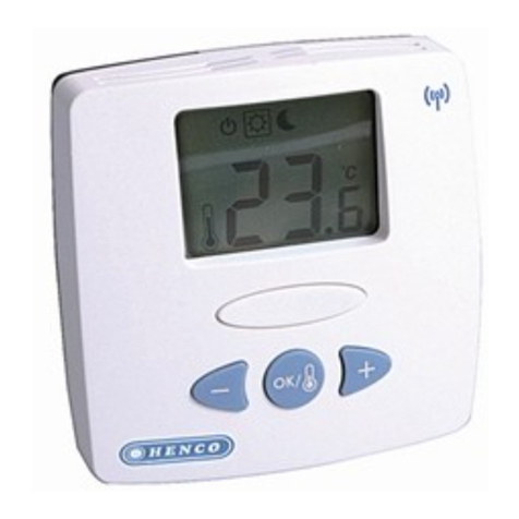
Henco LOGIC User manual

HENCO LOGIC
Wired digital room thermostat
English | Nederlands
Français | Deutsch HEATING UNDERFLOOR
HEATING

2
English | Nederlands | Français | Deutsch
TABLE OF CONTENT
General information.............................................................................................................................................................3
1. Presentation ......................................................................................................................................................................... 4
2. Box contents ........................................................................................................................................................................4
3. First Installation..................................................................................................................................................................5
4. Product description......................................................................................................................................................6
4.1 LCD logo description..........................................................................................................................................................6
5. Mode selection...................................................................................................................................................................7
5.1 Change temperature setting.........................................................................................................................................8
5.1.1 Boost/ Timer mode...........................................................................................................................................................8
5.1.2 Comfort mode ....................................................................................................................................................................8
5.1.3 Reduced / ECO mode.....................................................................................................................................................8
5.1.4 Anti-freeze mode ..............................................................................................................................................................9
5.1.5 OFF mode...............................................................................................................................................................................9
5.1.6 Reversible mode ................................................................................................................................................................9
6. Functions highlights...................................................................................................................................................10
6.1 Reversible mode ................................................................................................................................................................ 10
6.2 Opened windows detection........................................................................................................................................11
6.3 Keyboard locking.................................................................................................................................................................11
6.4 PIN code....................................................................................................................................................................................11
6.5 Heating and cooling indications...............................................................................................................................11
6.6 LED indication .......................................................................................................................................................................11
7. User parameters............................................................................................................................................................... 12
7.1 Access to user parameter menu............................................................................................................................... 12
7.2 User parameter description......................................................................................................................................... 13
8. Installer parameters..................................................................................................................................................... 16
9. Temperature sensors used for regulation ...........................................................................................20
9.1 Temperature sensors........................................................................................................................................................20
9.2 Description of regulation configurations............................................................................................................20
10. Troubleshooting & solution...........................................................................................................................21
11. Maintenance ....................................................................................................................................................................22
12. Technical characteristics....................................................................................................................................22
13. Standards.............................................................................................................................................................................23
14. Dimensions & weight............................................................................................................................................23

3
Deutsch | Français | Nederlands |English
GENERAL INFORMATION
Safety warnings and operating instruc-
tions
•This product should be installed preferably
by a qualified professional. Subject to obser-
vation of the above terms, the manufacturer
shall assume the liability for the equip-
ment as provided by legal stipulations.
•All instructions in this Installation & Operation
manual should be observed when working
with the thermostat. Failures due to improp-
er installation, improper use or poor main-
tenance are voiding manufacturer liability.
• Any
attempt to repair voids the responsibili-
ty and the obligation to guarantee and
replacement from the manufacturer.
•Do not cover the thermostat for accurate mea-
surement of ambient temperature. Therefore
the sensor must never be hidden behind
thick curtains, furniture, etc… Alternatively,
a remote sensor should be used.
•2012/19/EU (WEEE directive):
Products marked with this symbol can-
not be disposed of as unsorted
municipal waste in the European
Union. For proper recycling,
return this product to your local
supplier upon the purchase of
equivalent new equipment, or dispose
of it at designated collection points. For
more information see: www.recyclethis.info
Application
•The thermostat have been designed for use in
residential rooms, office spaces and industri-
al facilities. Verify that the installation com-
plies with existing regulations before opera-
tion to ensure proper use of the installation.
Please refer to “Quick Installation
Guide” for thermostat installation

4
English | Nederlands | Français | Deutsch
1. PRESENTATION
• Thermostat compatible with Logic Wired
system.
• 3 sensitive touch buttons.
• 4 wires connectivity.
• Different temperature modes setting.
• Anti freeze function.
• Configurable Hysteresis or PWM regulation.
• Pin Code & screws lock for public area.
• EEPROM non volatile memory.
• 2 parameter menus: User and Installer.
In option
External sensor with several possibilities of
regulation (Floor, remote, combined...).
2. BOX CONTENTS
HENCO Logic thermostat
Fixing screws Lock screws
Back cover
1 x
1 x 1 x
1 x

5
Deutsch | Français | Nederlands |English
3. FIRST INSTALLATION
Please refer to the Quick Installation Guide.
When thermostat is started, it launch is initialization
procedure:
All segment of the LCD screen are displayed
The led is blinking white
LCD screen display the software version
Thermostat initialize its internal configuration
according to H&C signal
A A
D
D
B
B
C
C
N
N
Lout
L
L
Henco Controller WFC only
Heat or cool signal
Clock signal

6
English | Nederlands | Français | Deutsch
4.1 LCD logo description
1 Icon showing current operating mode of
thermostat with left to right:
Thermostat is in master configuration
when logo mode is with frame .
Thermostat is in slave configuration when
logo is without the frame .
Boost/timer mode
Comfort mode in heating mode
Reduced / ECO mode
Frost protection mode
Off mode when “reversible” mode is
activated
2 Open window funct ion
3 Displaying of reduced clock and heating
& cooling order:
order is applied to heating system
order of reduced set point mode
order of cooling configuration
order of stop
4 Measured temperature/temperature
1
2 3 5
6
7
8
9
10
4
4. PRODUCT
DESCRIPTION
set point/remaining time for boost mode
5 Locked keyboard:
6 Parameter menu number:
7 Parameter menu:
8 Indication of heating & cooling
demand
9 Type of measured data & sensor used for
system regulation:
Humidity measurement & control
External temperture sensor
Internal temperature sensor
Ambient temperature sensor
Floor temperature sensor
10 Temperature units or or measure-
ment of humidity rate
Minus button or
down/left button for
menu navigation.
Plus button or up/
right button for
menu navigation.
Validation of temperature set point setting or accessing to
parameter menu or displaying measured
temperature/ temperature set point.

7
Deutsch | Français | Nederlands |English
5. MODE SELECTION
Press any key to wake-up the
thermostat and activates the back- light.
Hold key for 2 second to access to menu
for selection of mode.
Press or permits to change navigate in
different mode.
If “basic navigation” is activated, navigation
menu will be:
If “reversible mode” is activated (see paragraph
5.6 “Reversible mode” for more details), naviga-
tion menu will be:
Menu for mode selection
Boost, comfort, reduced, antifreeze,
or stand-by menus
or
Automatic selection of
current mode,
(no applicable for
Boost/timer mode and
reversible mode)
Selection of mode Parameter menu
No user action
after 5 s
2 seconds
5 seconds

8
English | Nederlands | Français | Deutsch
5.1 Change temperature setting
Wake-up the thermostat by pressing any key.
Press or , to change the temperature
set point (digits starts to blink).
By pressing validation key , temperature
set point value is validated.
5.1.1 Boost/Timer mode
In mode boost, set point temperature is
applied during a selected time.
After this time, thermostat will return to former
mode.
You can first adjust, the desired setting tem-
perature with or , press validation key
, to validate, default value 24°C.
In a second time, you can adjust the du- ration
in hours “H” if below 24H, then in day “d”.
With automatic H&C switching configuration,
boost/timer mode can’t be selected.
If configuration system is changed by H&C
signal, boost/timer mode will be stopped.
Thermostat will return to the previous select-
ed mode.
Default value: “no” (0 minute)
Value range: 1h to 23 hours (step of 1 hour)
and 1 day to 44 days (step 1 day).
5.1.2 Comfort mode
In this mode, comfort temperature set point
will be followed all the time.
This mode can’t be selected if thermostat is a
“slave” product and H&C signal sends reduced
information.
5.1.3 Reduced / ECO mode
In this mode, reduced temperature set point
will be followed all the time.
This set point corresponds to comfort set point
reduced by an offset (see paragraph 7.2 “User
parameter description”).
Reduced/ECO mode is available if if thermostat
is in master configuration;
If H&C signal is in ECO mode and the thermo-
stat is configured in slave, the thermostat is set
automaticaly in ECO configuration
Note: In cooling mode, reduced mode acts
like the OFF mode (system is stopped, NC
actuators are closed).
Thermostat is in master configuration when
logo mode is .
Thermostat is in slave configuration when logo
is without the frame .
Important notes:
- With “Floor Limit” regulation, Reduced/ ECO
mode couldn’t work properly if “Low limit”
value is too high;
- If system configuration is automatic H&C
switching and thermostat is system master,
user can’t set derogation.
- If configuration system is changed by H&C
signal, setpoint derogation will be stopped.
5.1.4 Anti-freeze mode
Use this mode if you want to protect your

9
Deutsch | Français | Nederlands |English
installation against freezing. (default value 7°C).
Remark: in cooling mode, Anti-freeze mode
acts like the OFF mode (system is stopped).
If “floor limit” regulation is set by user/ installer,
selecting anti-freeze mode stops “floor limit
regulation”.
Antifreeze temperature setpoint is applied
when opened window is detected.
5.1.5 OFF mode
Use this mode if you need to switch off your
installation.
Be Careful: In this mode your installation can
freeze.
- With off mode, “floor limit” regulation is
stopped.
5.1.6 Reversible mode
This mode allow to switch between the heat-
ing and cooling system, the changeover can
be managed by the thermostat in Master
mode (manual or automatic) displayed in Slave
mode (H&C signal at the thermostat input).

10
English | Nederlands | Français | Deutsch
6. FUNCTIONS HIGHLIGHTS
6.1 Reversible mode
Reversible menu access
Enter user parameter 07, use keys and
, to select operating mode of the thermostat:
- Hot : Heating regulation mode
- CLd : Cooling regulation mode
- rEv: activation of reversible mode in menu
- Aut : automatic Heat/Cool mode.
Pressing key confirms the selection and
switches to comfort mode.
A user inactivity of some seconds confirms
cur- rent selection and returns to old selected
mode.
By pressing key, temperature set point
value is validated.
Once the reversible mode has been selected,
the change of mode is made as follows:
Press 2s on to access the menu mode
selection menu. Then go down below the
OFF mode until the 4 blank icons are dis-
played:
Select with then select the «Hot» heating
mode or «Cld cooling mode using and
keys.
Pressing the key for 1s confirms the mode
selection.
User inactivity of a few seconds keeps the
thermostat in the previous mode.
Back to previous mode Navigation menu Comfort or Eco mode
automatic
return
Reversible menu
Heating mode Cooling mode Auto H&C mode
1 second Short push
or

11
Deutsch | Français | Nederlands |English
Temperature LED color
T ≤ 18°C blue
18°C < T ≤ 20°C azure
20°C < T ≤ 22°C green
22°C < T ≤ 24°C orange
T ≥ 24°C red
6.2 Opened windows detection
Enter user parameter 06.
When activated and a detection is running,
the icon will appear and blink on the
screen!; This function is done by measuring
and recording the temperature evolution.
When an opened window is detected, the
thermostat applies to heating system anti-
freeze temperature set point. User can restart
heating system, and stops window detection
by pressing on a key.
6.3 Keyboard locking
Wake-up the thermostat (lighted back- light),
Press and hold and keys simultane-
ously.
Once locking is activated, logo appears on
the LCD screen:
6.4 PIN code
To activate this function enter user parameter
9.
The PIN code protect the thermostat from any
change of the setting as temperature or mode.
When user pushes a key, “PIN” will be dis-
played. If user press another time a touch, he
has to enter PIN number.
6.5 Heating and cooling
indications
Logos used to indicate than system
requires:
heating is ; cooling is .
6.6 LED indication
When user modify set point temperature in
functioning mode, behavior information is dis-
played with a LED RGB located on the middle
of validation key.

12
English | Nederlands | Français | Deutsch
7. USER PARAMETERS
7.1 Access to user parameter menu
Automatic return (10 seconds of keyboard inactivity)
Mode selection menu
Screensaver
2 seconds 5 seconds
10 seconds without
user action
Parameter menu
Press any key to wake-up the thermostat and
activates the backlight.
By pressing key during 5 seconds, user can
access to parameter menu.
The menu scroll is done with keys and
. Menu is selected by pressing key ,
value starts blinking. Once in the menu, the
parameter value is changed with the keys
and .
Pressing again key sets the parameter
value.
Note: Thermostat parameters are divid- ed
into two groups: user and installer (advanced
menu).
Boost, comfort, reduced, antifreeze,
or stand-by menus

13
Deutsch | Français | Nederlands |English
ECO/Reduced offset setting
Default value: 2.0°C Values: 0.0°C to 5.0°C
“basic navigation” mode
“Yes”: Activation of function, restrict to comfort and off mode.
“no”: No activation
Default value: no Values: Yes / no
Room temperature display
“Yes”: remote displays measured temperature
“no”: remote displays set point temperature
Default value: Yes Values: Yes / no
Calibration of internal room sensor (remote)
This menu is only displayed if parameter rEG (#20) is set with “Air”
or “Fll”.
Calibration must be done after a given order has been operating
for a day. Place the thermometer in the middle of the room at
about 1.5 m above the floor. Record the temperature shown after
1 hour. When you enter calibration mode, displaying of logo
means no calibration has been performed yet. Enter the reading
on your thermometer using minus and plus keys (step of
0.1°C).
The setting is validated with validation key. logo appears to
indicate that calibration.
If user press simultaneously minus and plus keys, sensor
calibration is reset. logo disappears.
Important note: a large temperature deviation may indicate an
inappropriate installation of the thermostat. If the temperature
difference is too big, this could mean your thermostat was not
installed properly e.g. in the right place.
Default value: 0.0°C Range value: -5.0°C and 5.0°C
7.2 User parameter description

14
English | Nederlands | Français | Deutsch
Calibration of external room sensor (remote)
This menu is only displayed if parameter rEG (#20) is set with “Amb”
or “Flr” or “Fll”.
Calibration must be done after a given order has been operating
for a day. Place the thermometer in the middle of the room at
about 1.5 m above the floor. Record the temperature shown after
1 hour. When you enter calibration mode, displaying of logo
means no calibration has been performed yet. Enter the reading
on your thermometer using minus and plus keys (step of
0.1°C).
The setting is validated with validation key. logo appears to
indicate that calibration.
If user press simultaneously minus and plus keys, sensor
calibration is reset. logo disappears.
Important note: a large temperature deviation may indicate an
inappropriate installation of the thermostat. If the temperature
difference is too big, this could mean your thermostat was not
installed properly e.g. in the right place.
When user changes this parameter, regulation will restart.
Default value: 0.0°C Range value: -5.0°C to 5.0°C
Open window detection
“Yes”: activation of function
“no”: no activation
If function is active, logo
More information is in paragraph “Opened window detection”
Default value: Yes Values: Yes / no
Authorization or not of cooling mode
This parameter menu allows to enable or disable cooling in spe-
cific room like bathroom.
When the system is in cooling mode, the thermostat is switched
in Off mode.
Default value: Yes Other value: no
Operating mode of thermostat
- Hot: heating mode
- CLd: cooling mode
- Aut: automatic mode
- Rev: displaying of reversible menu (see paragraph 5.6
“Reversible mode”)
Default value: Hot Values: Hot / Cold / Aut / Rev

15
Deutsch | Français | Nederlands |English
Setting value for PIN code
This menu is only displayed if parameter Pin (#09) is set with
“Yes”.
User has to configure values of the three digits with and validate
its choice with validation key .
Default value: 000 Value range: 000 to 999
Displaying client software version
Pressing and maintaining validation key displays software
qualification version and debug information.
Reminder: software version is written: Vxx.xx
Degree unity for displaying
°C : Celsius
°F : Fahrenheit
Default value: °C Values: °C /°F
Reset user settings:
Press and hold for 5 seconds to reset, all segments light up,
showing that the thermostat has been reset with the factory
default setting:
Set point temperatures in modes,
All user parameters with their factory values.
When button is hold:
Clearing user parameters
holding
button
holding
button
releasing
button
Clearing
is done
PIN code activation
“Yes”: activation of function
“no”: no activation
More information is in paragraph “PIN code & remote locking”
Default value: no Other value: Yes

16
English | Nederlands | Français | Deutsch
Professional menu
This menu permits to access to installer parameter menus.
Pressing and maintaining validation key displays first param-
eter of installer menus.
When validation/menu key is hold:
User menu exit
Press validation key to exit user menu and return to the
main screen.
Accessing to installer parameters
holding
button
holding
button
releasing
button
or
Installer
parameters
8. INSTALLER PARAMETERS
Modification of these parameters is reserved for professionals.
To access to these installer parameters, installer has to go to user parameter number 14. After, he
presses and holds validation/menu key during 5 seconds.
Selecting temperature sensor used for the regulation
- AIR: regulation with internal sensor
- Amb: regulation with external sensor
- FLR: regulation on floor sensor (external sensor of remote)
- FLL: regulation with floor sensor and air sensor
To select “Amb”, “FLR” or “FLL” regulations, external sensor has
to be connected to thermostat. (see paragraph 9 “Temperature
sensors used for regulation” for more information).
Default value: Air Other values: Amb / FLL / FLR
Accessing to installer parameters
holding
button
holding
button
releasing
button
Installer
parameters
Wired PiLote configuration
Using H&C or clock signal, thermostat has to be defined in slave
or master configuration.
- “SLA”: slave configuration
- “MAS”: Master configuration
Default value: SLA Other value: MAS
or

17
Deutsch | Français | Nederlands |English
Regulation type
- HYs: regulation of hysteresis
- bP: regulation of proportional type
Default value: bP Other value: HYs
Hysteresis value
This menu is displayed only if parameter “Typ” (#26) is equal to
“HYs”.
Use minus and plus keys to set hysteresis value.
The setting is validated with validation key .
Default value: 0.3°C Value range: 0.2°C to 3°C
Lower limit of floor temperature (FL.L)
This value is displayed and set only if parameter 21 is FLL.
This value of “low limit” will be used in heating and cooling config-
urations. Press to increase the value
Default value: “no”: not activated
Other values: 5°C to “FL.H” (or 40°C)
High limitation of floor temperature (FL.H)
This value is displayed and set when parameter 21 is set on FL.L.
This value of “high limit” will be used in heating and cooling con-
figurations. Press to decrease the value.
Default value: “no”: not activated
Other values: “FL.Lo” (or 5°C) to 40°C
Displaying of measured temperature by internal sensor
If “Err” is displayed, internal sensor is damaged.
Displaying of measured temperature by external sensor:
FLOOR temperature / AMBIENT temperature
If “Err” is displayed, external/ambient sensor isn’t connected or
damaged.

18
English | Nederlands | Français | Deutsch
Cycle time setting
This menu is displayed only if parameter “Typ” (#26) is equal to
“bp”.
Use minus and plus keys to set cycle time value.
The setting is validated with validation key .
Default value: 10 minutes Other values: [10 15 30 45 60]
Proportional Band
This menu is displayed only if parameter “Typ” (#26) is equal to
“bp”.
Use minus and plus keys to set proportional band value.
The setting is validated with validation key .
Default value: 2°C Value range: 2°C to 5°C
First parameter of H&C signal: width of death band
This menu is displayed only if parameter “Mod” (#07) is equal to
“Aut” or “Aut” is selected in “Reversible” mode menu.
This parameter corresponds to width of death band.
Use minus and plus keys to set value.
The setting is validated with validation key .
Default value: 1°C Value range: 0°C to 5°C by step of 0.5°C
Second parameter of H&C signal: time threshold
This menu is displayed only if parameter “Mod” (#07) is equal to
“Aut” or “Aut” is selected in “Reversible” mode menu.
This parameter corresponds to a time threshold.
Use minus and plus keys to set value. The setting is vali-
dated with validation key .
Default value: 1H Other values: no, 30’, 2H, 3H, 4H and 5H
Minimum value of setting range of the set point
temperature
Default value: 5.0°C Value range: 5.0°C to 15.0°C
Maximum value of setting range of the set point tem-
perature
Default value: 30.0°C Value range: 20.0°C to 37.0°C

19
Deutsch | Français | Nederlands |English
Installer menu exit
Press validation key to exit user menu and return to the
main screen.
EEPROM clearing
All thermostat parameters will be loaded with factory settings.
Pressing and maintaining validation key displays:
Anti-condensation function of the installation:
only with RH sensor
When condensation is detected, air conditioning is stopped or/
and dehumidifier is activated.
Default value: Yes Other value: no
Anti-short Cycle time ON
Setting time value of minimum ON-state load.
Time value is a number of minutes.
Default value: 2 minutes Other value: no to 5 minutes
Anti-short Cycle time OFF
Setting time value of minimum OFF-state load.
Time value is a number of minutes.
Default value: 2 minutes Other value: no to 5 minutes
Pump and valve exercises
Activation or not of system exercise function.
Default value: Yes Other value: no
Accessing to installer parameters
holding
button
holding
button
releasing
button
Clearing
is done

20
English | Nederlands | Français | Deutsch
9. TEMPERATURE SENSORS USED FOR REGULATION
9.1 Temperature sensors
Thermostat can measure temperature from two different sensors:
Internal sensor: this sensor is embedded on thermostat.
External sensor: This sensor is plugged at the back of thermostat. It can be used as “ambient”
temperature sensor or as floor temperature sensor depending of regulation configuration.
9.2 Description of regulation configurations
Heating and cooling regulation can use two different temperature sensor. With respect of
external sensor connection, installer can choose a regulation type in parameter 20 in installer
menu (see paragraph 8 “Installer parameters”).
Important points:
to be able to select “Amb”, “FLR” or “FLL” regulations in installer menu, external sensor has
to be connected to thermostat.
If there is an error with external sensor and if installer/user goes to parameter menu n°20,
“AIR” regulation will be selected automatically and external sensor error could be deleted
if thermostat is turned off.
Regulation
configuration Sensor LCD
displaying Description
AIR Internal
Air regulation is done with internal sensor.
Sensor measures temperature at the
thermostat position.
Amb External
Ambient regulation is done with external
sensor.
Sensor measures at a different position than
thermostat position.
FLR External
Floor regulation is done with external sensor.
External sensor is connected to digital
thermostat and placed “in the floor”.
FLL Internal &
external
Floor limit regulation with external sensor
and internal sensors.
External sensor is connected to digital
thermostat and placed “in the floor”.
This measurement permits to check floor
temperature limits. Internal sensor is used to
do temperature regulation.
Table of contents
Languages:
Other Henco Thermostat manuals
Popular Thermostat manuals by other brands
Adax
Adax Glamox Professional Heating quick start guide
HYSEN
HYSEN HY02TP WIFI user manual
White Rodgers
White Rodgers 1F95-71 installation instructions
MIKOTERM
MIKOTERM mControl HT300 SET user manual
olympia electronics
olympia electronics BS-844/2 quick start guide
Network Thermostat
Network Thermostat RP32-NX Installation and programming instructions


