Hengstler C-56 User manual
Operator Manual
Thermal Printer
C-56
E
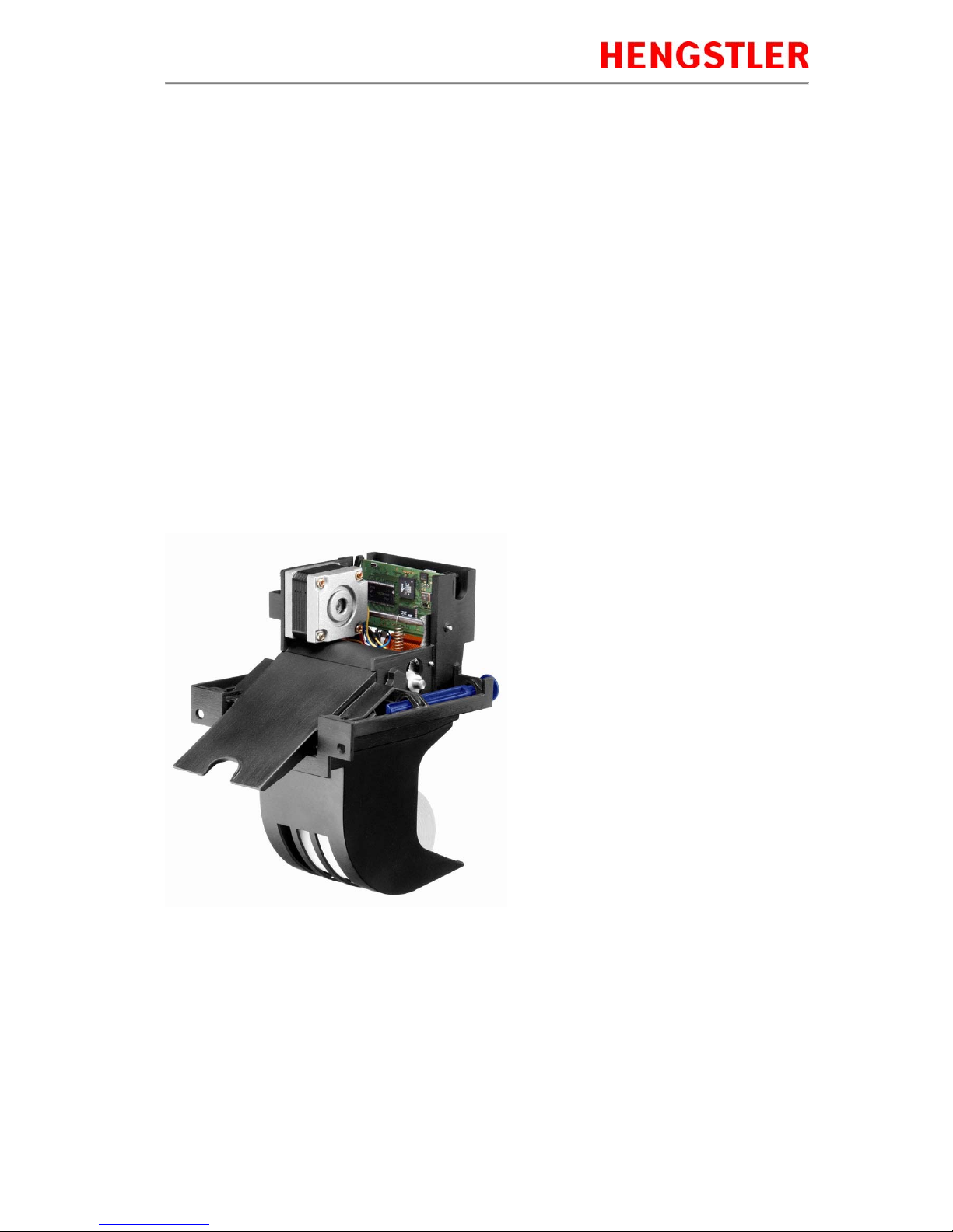
Thermal Printer C-56
Part No. 2 684 019 Rev. No. 4310715 eli page 2of 17
Release
Release 1.0
C.Bernhart Mar 03th, 2005
Approved Hengstler E.Link
Approved
Changes
Date Rev Additional Content
09 Nov 2004 1.0 First Release
03 Jun 2005 1.1 RS 232 extension
26 Jul 2005 1.2 Update technical data, troubleshooting
17 Jul 2006 1.3 Update USB cable spec; add safety hint
21 Jan 2008 1.4 Update spare parts; add EMC hints; adding sensor options
15 May 2009 1.5 Revise EMC specs.
5 Aug 2009 1.6 Add 12 volt specs, chute sensor, hardware PPE sensor. Add reference to short
chute shroud.
17 Oct 2011 1.7 Add limitation on reversing paper. Added German paper specification. Removed
reference to German operating manual with wrong P/N.
3 Apr 2013 1.8 Clarify serial pinout; add wiring diagram for serial connectioncable; correct height-
width-depth abbreviations; modified warning definition;
30 Jul 2015 1.9 Addition of chapter 2.3 and power supply pinout; various minor corrections
© 2005 - 2015 by HENGSTLER
This document is protected by copyright by HENGSTLER GmbH.
This document may not be changed, altered, duplicated or reproduced in any manner, or provided
or transmitted to any third persons or organizations, without the prior written approval of
HENGSTLER.
We reserve the right to make technical changes, modifications or improvements without prior
notice.
Hengstler and the Hengstler logo are registered trademarks of Hengstler GmbH. Other brand and
product names used herein are trademarks or registered trademarks of their respective companies.
HENGSTLER GmbH
Uhlandstr. 49
78554 Aldingen / Germany
Tel. +49 (0) 7424-89 0
Fax +49 (0) 7424-89 500
www.hengstler.com

Thermal Printer C-56
Part No. 2 684 019 Rev. No. 4310715 eli page 3of 17
Contents
RELEASE.............................................................................................................................. 2
CHANGES............................................................................................................................. 2
1.0Introduction ..................................................................................................................... 4
1.1ADDITIONAL LITERATURE.......................................................................................... 4
2.0Important Information and Safety Instructions.............................................................. 5
2.1GENERAL INFORMATION........................................................................................... 5
2.2SYSTEM-SPECIFIC SAFETY INSTRUCTIONS AND SYMBOLS....................................... 5
2.3PRINTER INSTALLATION........................................................................................... 6
3.0Layout and Function........................................................................................................ 7
3.1STRUCTUREOFTHEC-56THERMALPRINTER ............................................................... 7
3.2FUNCTIONS OF THE PRINTER..................................................................................... 8
4.0Operation........................................................................................................................ 10
4.1START UP OF THE SYSTEM ..................................................................................... 10
4.2LOADING OF PAPER ............................................................................................... 10
5.0Troubleshooting............................................................................................................. 11
5.1CLEARING PAPER JAMS ......................................................................................... 12
5.2REPLACEMENT OF COMPONENTS............................................................................ 13
6.0Technical Data............................................................................................................ 14
6.1GENERAL DATA..................................................................................................... 14
6.2CONFIGURATION OF THE INTERFACES...................................................................... 15
6.3PAPER SPECIFICATIONS......................................................................................... 16
6.4DATA SPECIFIC TO PRINTING................................................................................... 16
6.5ORDER NUMBERS FOR SPARE MODULES:................................................................ 16

Thermal Printer C-56
Part No. 2 684 019 Rev. No. 4310715 eli page 4of 17
1.0 Introduction
Thank you for selecting the Hengstler C-56 printer! We are proud of this feature-rich product, which was
designed using all our expertise and experience, and we are confident that you will be pleased withthe
advanced features and outstanding performance.
This Operator Manual is designed to help you with the proper installation, connectionto your host computer
system and start-up of the C-56 thermal printer system. All necessary details will be further explained in the
following sections. Please read this manual carefully before starting up the thermal printer. If you have any
further questions, please do not hesitate to contact our head office or one of our branch offices.
The thermal printer does not require any servicing and isintended primarily for printing documents and receipts,
at a printing speed up to 220 mm/sec for the 24 VDC version, and up to 160 mm/sec for the 12 VDC version,
when powered by an appropriate power supply and when printing on endless thermal paper with paper weight
ranging from 50 to 60 g/m2. The paper width may vary from 58 to 60 mm (2.28" to 2.36"). Whiledocuments may
be any length greater than 120 mm, most documents will fall in the range of 120 to 297 mm.
The horizontal andvertical print density is 203 dpi sothat graphics, such as logos etc. can be printed with good
quality.
The printer mechanism has been designed in particular for application in self-service gasoline pumps in service
stations, in terminals and vending applications. The modular design enables the main components to be
replaced in less than 2 minutes. The controller integratedin the printer mechanism controls all printing functions
and is provided with an USB 1.1 port for the host computer. Driver software is available that supports the
Windows XP/7/8/10 and Linux operating systems. In addition, the printer can also be activated directly in ASCII
mode through ESC/FS sequences; a detailed description of the different sequences is contained in the
Emulation Manual.
1.1 Additional Literature
C-56 Emulation Manual D 684 017
Paper Specification (English)
Paper Specification (German) D 684 012
D 684 010
Dimensional Drawing D 684 048 etc; see the C-56 download area at www.hengstler.de

Thermal Printer C-56
Part No. 2 684 019 Rev. No. 4310715 eli page 5of 17
2.0 Important Information and Safety Instructions
2.1 General Information
The company Hengstler GmbH will not accept any liability for direct or consequential damages arising due to
improper use of the thermal printer and, in particular, due to non-compliance with this operating manual or to
improper handling and maintenance. Thesupply of technical documentation does not imply any authorization by
Hengstler GmbH to make additions, repairs or modifications.
This documentation may not be copied, norshall its contents be disclosed or used commercially unless this has
otherwise been explicitly agreed. The user is responsible for proper handling and installation of the printer. The
printer should only be shipped in its original packing.
2.2 System-Specific Safety Instructions and Symbols
Hengstler GmbH will not accept anyliability for the safe operation ofthe C-56 thermal printer unless Hengstler
original products are used exclusively and the following instructions andrecommendations are heeded.
If unauthorized persons perform any repairs ormodifications to theprinter mechanism andthe
controller, HENGSTLER will not accept any liability andthe guarantee shall be void.
Unapproved types of thermal paper may dramatically reduce the life of the print head and may
void the guarantee. For pre-printedthermal paper make sure that only appropriate inks are
used. Details can be found in the Hengstler Paper Specifications D 684 012.
The connector for the power supply must not be plugged in or disconnected under load in order
to avoid damage to the electrical components and the thermal printhead.
Avoid strong vibration, shocks and impacts since they may damage or even destroy sensitive
electronic and mechanical components. Do not touch the surface of the printer control board in
order to prevent static electricity from damaging sensitive components.
The thermal printer must not be used nearto high-frequency apparatus or strong magnetic fields
in order to prevent undefinedmagnetic disturbance.
Do not make any attempts to service this printer (e.g. change paper) whilethe printeris printing.
Installing or uninstalling the printer must only be done while using adequate ESD protection.
The following symbols on the system and in the manual remind you to follow the relevant safety
instructions:
General warning for cases where the useror service personnel may be in danger.
General notes and hints for operating thesystem safely.

Thermal Printer C-56
Part No. 2 684 019 Rev. No. 4310715 eli page 6of 17
2.3 Printer Installation
The C-56 printer uses electrically conductive housing materials which help to eliminate electrostatic charging
during printing. In order to protect the printer from damages caused by externally applied charges, e.g. when
electrostatically charged customers grabthe receipt at the printer chute,the printer must be grounded.
The mounting holes of the printer’s base unit can be utilized for this where a ground wire with lug may be
inserted in one ofthe two screw points.
If the printer is mounted in an electrically conductive and already grounded panel, additional wiringcan be
omitted if sufficient electrical contact is ensuredthrough the mounting points.
Caution:
The C-56 printer mouting must ensure permanent electrical connection of the printer’s base unit to
ground. This measure serves the draining of externally applied electrostatic charge.
Thermal Printer C-56
Part No. 2 684 019 Rev. No. 4310715 eli page 7of 17
3.0 Layout and Function
All modules of the C-56thermal printer mechanism are delivered in operating condition. After connecting the
printer to a USB 1.1 or 2.0 port on the host system (PC)and to a properly rated 24 VDC or 12 VDC power supply
(depending upon the model), and installing the driver software (if needed), the printer is ready for operation.
This thermal printer is a built-in module to be operated only as part of an overall system like e.g.
a vending application. Please, also consider the storage and operating conditions (see also
under chapter 6- Technical Data).
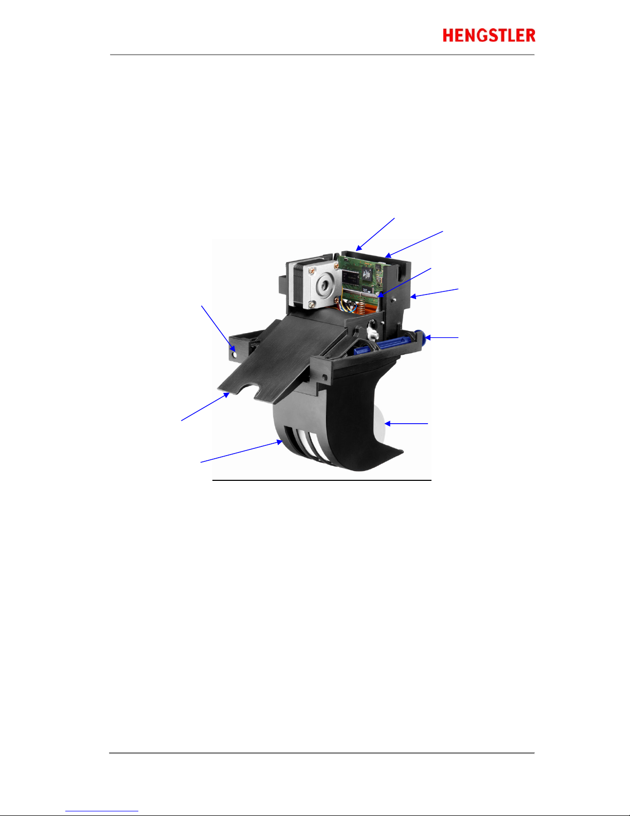
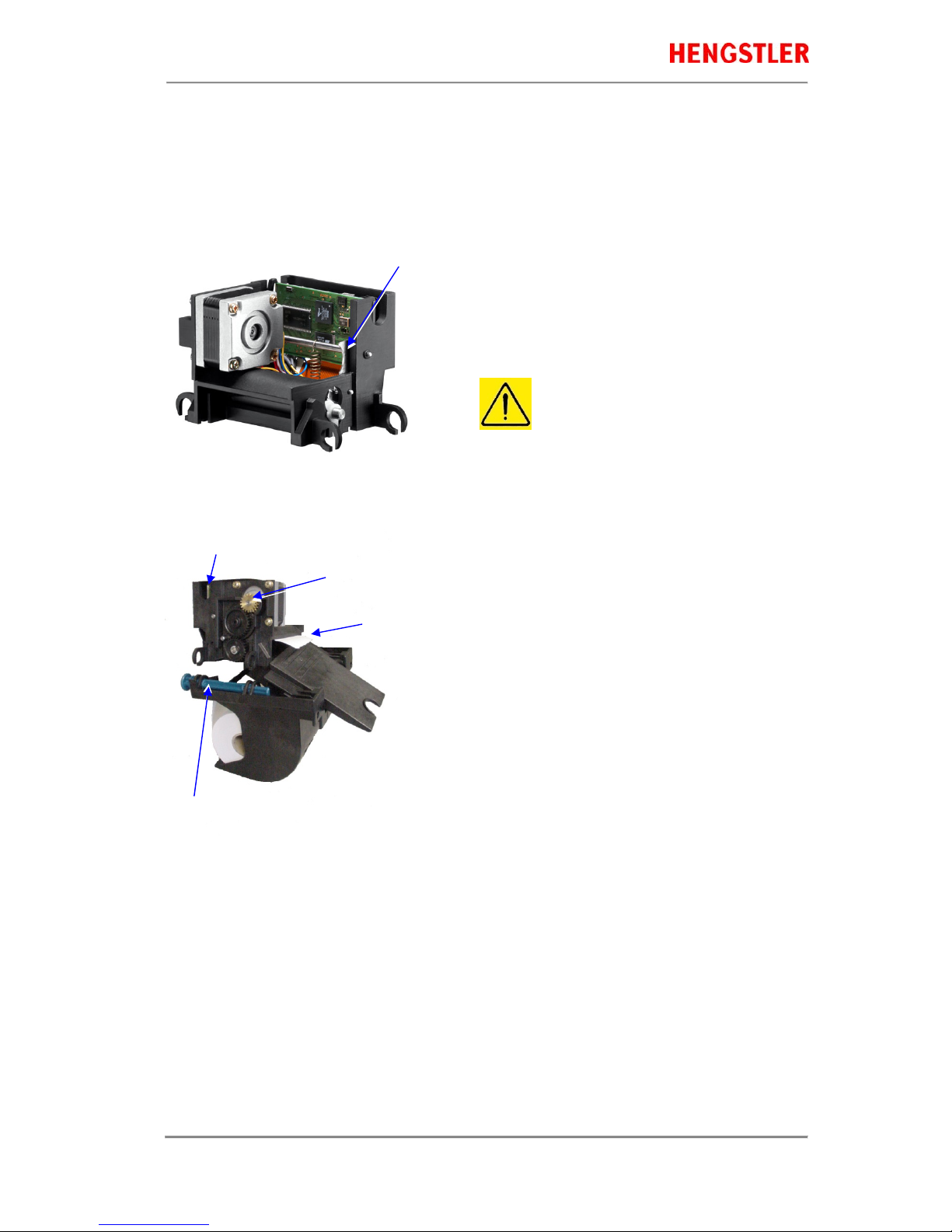
3.1 Structure of the C-56 Thermal Printer
Fig.1 Thermal printer, front view left hand
The C-56 Thermal Printer is composed ofthree main units:thermal printer with integrated Controller, basic unit
with paper tray and two hinge pins, and an eject chute supported by the basic unit. These hinge pins securethe
printer mechanism on the basic unit. If both hinge pins are retracted in part, the printer mechanism can be re -
moved. If only one hinge pin is retracted, the printermechanism can be pivoted around the remaining hinge pin.
The Eject Chute is provided with guides that engage in the basic unit firmly and with high dimensional accuracy.
The paper roll liesin the paper tray loosely. The sensitive side of the thermal paper must be outside or be
directed upward.
Note: A shorterEject Chute is also availablefor OEM applications. When this shorter chute is
used, an external, customer-supplied shroud must be used! Failure to usethis shroud will
cause increased paper jams. Contact Hengstlerfor details ofthe shroud design.
In Fig. 1, the protective plastic cover has been removed (also see Fig. 2) to provide a view of the
controller board. But for operation, this plastic cover must be in place.
USB or RS232 Interface,
DC power connector on controller board
Thermal printer mechanism
Hinge pin
Thermal paper roll
Mounting holes
Eject chute
Base unit with paper tray
Optional Paper Pre-End
Sensor connection
Printhead up lever

Thermal Printer C-56
Part No. 2 684 019 Rev. No. 4310715 eli page 8of 17
3.2 Functions of the Printer
The printhead of the C-56 printer mechanism has a horizontal resolution of 203 dpi (dots per inch). Thus, the 448
dots allow printing of lines with a maximum width of56 mm. The stepper motor affects the paper feed by means
of a platen that is rotated via gearing. The transmission ratio of this gearing has been selected insuch a way that
the vertical dot resolution is also 203 dpi; this corresponds to a paper movement of 0.125 mm. All functions of the
printer mechanism are controlled by the integrated Controller.
Fig. 2 Diagram of paper transport
The paper is inserted into the printer through the upper and lower paper guides and led over the platen. As soon
as the reflective LED sensor L1a in the upper guide detects the front paper edge, 'automatic paper insertion' will
start and the paper is transported until its front edge can be seized in the eject chute. The LED L2 signals that
the printer is ready by flashing slowly.
In the event the paper edge is not detected within approximately 5 seconds, the printer will
assume a malfunction and LED L2 (on the component side of the controller board) will flash
rapidly, indicating 'No paper/paper end'. The paper loading process is then aborted and must be
repeated.
As an alternative, the reflective LED sensor L1b may be installed instead of the sensor L1a. It will detect the
paper edges and recognizeposition identificationmarks (Black Marks) on the back side ofthe paper. The
ejected paper is cut when the user pulls it from the printer, thereby tearing it straight over the cutter. The shape of
the triangle cutter knife provides for a clean cut. The further paper transport will be carried out by program
control.
Optional reflective LED sensor L3 detects the presence of paper in the eject chute. The status of L3 can
determined via the Query command and is reported as part of the C-56 status bytes. See the C-56 Emulation
Manual D 684 017 for details on querying this sensor and theformat of the response.
Thermal Printer C-56
Part No. 2 684 019 Rev. No. 4310715 eli page 9of 17
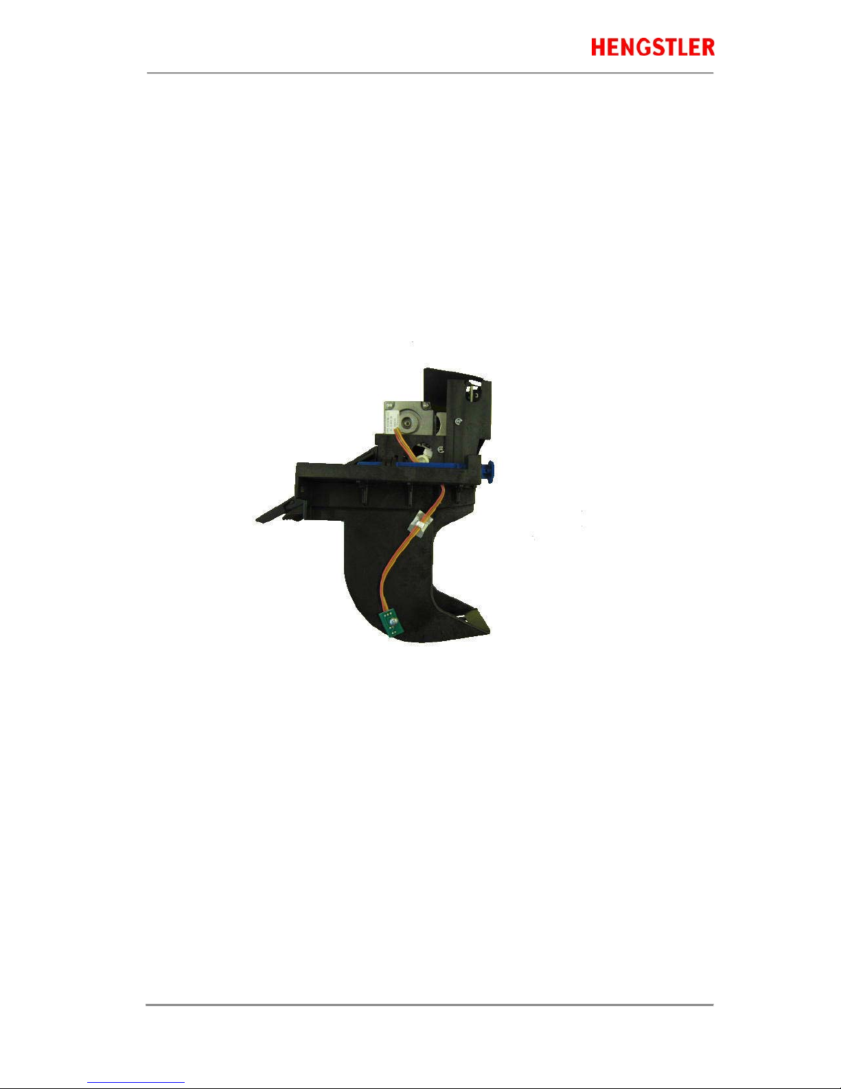
Optional reflective LED sensor L4 is located on the left outside of the paper reservoir and detects when the
diameter of the paper roll decreases below afixed dimension, indicating that paper is low. This is a hardware
alternative to the default paper low system, which requiresthermal paper with black marks atthe end of the
paper roll. The status of L4 can determined via the Query command and is reported as part of the C-56 status
bytes. See the C-56 Emulation Manual D 684 017 for details on querying this sensor and the format of the
response.
In case of any trouble during paper feed, the printhead can be lifted from the platen manually
using the “printhead up” lever so that the paper can be pulled out of the printer mechanism.
Caution !
Do not lift the printhead during printing or the thermal printhead may be damaged or destroyed
by overheating.
Fig. 2a C-56 with Hardware Paper Low Sensor

Thermal Printer C-56
Part No. 2 684 019 Rev. No. 4310715 eli page 10 of 17
4.0 Operation
Once the C-56 thermal printer is connected to the power supply and the host's interface port, and the driver (if
needed) is installed, the printer is ready for use.
4.1 Start up of the System
Fig. 3 Connections of the thermal printer to the system
1.
The connection to power supply is to be done
exclusively by means of the supplied cable.
Make sure that the power supply is always
switched off before the connector is plugged in or
removed. The locking tab of the connector should
always be directed towards the paper insert side.
2.
Connect the a) mini - USB port of the printer
mechanism with a USB – interface, or b) micro -
RS232 port with a RS232 interface of your PC,
using the supplied USB / RS232 cable.
On USB, Windows will then automatically
recognize the new connected device and install
the appropriate driver software.
3.
Install the driver software on the host system (PC).
Please, consider the coordination of the drivers with
the operating systems and respect the current
instructions supplied together withthe drivers.
4.2 Loading of Paper
Please only use paper of the recommended quality. Thermal paper with other specifications or poorer
quality may reduce theservice life of the thermal printhead considerably and will invalidate the printer's
warranty.
Fig. 4 Loading of the paper roll
1. Pull the protective sheathingfrom the paper roll
and cut the paper end at right angles to the
direction of feed as far as possible. Truncated,
lacerated or folded paper edges can produce a
paper jam duringautomatic insertion. Also
perforations of the paper web or rounded edges
are not acceptable.
2. Lay the paper roll into the paper tray as shown in
the illustration. The thermal sensitive paper surface
must be situated outside or on top.
3. Insert the paper into the printer mechanism. As
soon as the sensor in the paper guide detects
paper, the controller starts the automatic paper
insertion.
4. Cut off the paper appearing in the eject chute by
pulling it straight out.
Mini - USB
Locking tab
Connector
Power Supply
Micro – RS232
Be sure to use the supplied
cable tie to secure the RS-
232 cable and avoid possible
damage to this connector.

Thermal Printer C-56
Part No. 2 684 019 Rev. No. 4310715 eli page 11 of 17
5.0 Troubleshooting
The paper path inthe printer mechanism is almost straight so that proper paper feed andguiding will prevent
paper jams (see also Fig. 2). The following malfunctions if any will be recognized and signaled by the integrated
controller:
Paper Insert Error In case the 'Automatic Paper Insertion' starts, but the paper has been held
back by hand too long time or has been fed in skewed, the paper path can
indicate a ‘Paper Insert Error’ caused by a time out of the sensor routine.
As failure corrective action, pull the paper back. In case the paper has
already been transported by the platen, left the printhead, pull back the
paper and restart the loading procedure.
No Paper Insertion In case the ‘Automatic Paper Insertion’does not start andthe motor stalls,
with a characteristic rattling sound. If the printer has been left with no paper
inserted for a longer period (e.g. a day or more), the printhead can cause a
temporary depression of the platen and the motor will not start turning.
Lift the printhead using the head lift lever (see Fig. 5) and insert paper.
Release the headlift lever after themotor begins to runsmoothly and the
platen begins to pull the paper. Continue the auto loading procedure.
Paper Jam During operation, a paper jam may occur in the eject chute due to paper
scraps, etc. Jamming may also occur from reversingthe paper for morethan
the 150 mm specified maximum reverse distance.
As failure corrective action, tilt the printer mechanism open and remove
any paper scraps found at the entrance into the eject chute. In case the eject
chute has been clogged deliberately (vandalism), the chute will have to be
dismounted and cleaned. Afterwards repeat the paper loading routine.
Paper End The sensor L1 (a or b, depending upon thevariant of sensor placement) will
detect the end of the paper, e.g. in case of a torn paper web.
As failure corrective action, remove the document that has already partly
been printed (see Paper Jam) and repeat the paper loading routine. If
necessary, load a new paper roll.
Paper Pre-End The sensor L1 recognizes the 'paper pre-end mark' so that the controller can
transmit the status message 'Paper Pre-End' upon receipt of the Query
Status command. Alternatively, if so equipped, sensor L4 will detect that the
paper roll diameterhas decreased to thepoint that it is nolonger reflecting
the side of the paper roll when in the rest position, and will transmit the
‘Paper Pre-End” status message when queried. In either case, the printing
of further documents will not be blocked unless the printer detects 'Paper
End'. A new loading operation will cancel this message.
Undefined Error In case none of the above mentioned failures is detected, the printer may be
blocked by the operating system because e.g. the printer is not recognized
by the PC. If noother obvious disorder of the operating system is found, we
recommend as failure corrective action to disconnect the USB cable from
the PC. The operating system will then deactivatethe driver software. Re-
establish theUSB connection after aninterruption ofabout 1 minute inorder
to re-activate the driver software.
Thermal Printer C-56
Part No. 2 684 019 Rev. No. 4310715 eli page 12 of 17
5.1 Clearing Paper Jams
In order to clear a paper jam, detach the document that is already present in the eject chute and retract the
remaining paper manually. Paper scraps remaining in the area between the print mechanism and eject chute can
be removedafter the printer is tilted open.
Fig. 5 Open paper path for removing paper
In case there is still paper between the printhead and the
platen, remove the friction between head and platen by
pressing down the lever andthen pull the paper back by
hand.
Never actuate this lever during the printing
operation or else the printhead will overheat.
Fig. 6 Tilt the printer mechanism open for paper removal
If a partly printed document remains in the printer
mechanism, e.g. in the event of a paper end signal due to
a tear, and it does not appear in the eject chute, the
printer mechanism will have to be tilted open and the
document be taken out by hand. Note that additional care
must be taken concerning wire routing if the optional
chute sensor or hardware paper-low sensor are installed.
1.
Pull the hinge pin back into its tilt position.
2.
Then tilt the printer open as illustrated. Now, the
partially printed document will be visible and can be
pulled out over the eject chute.
3.
Eject the document by twisting the motor pinion gear
clockwise untilthe document leaves the friction area
of the platen.
4.
Remove the partially printed document. Then again tilt
the printer mechanism back into its operating position
and secure it by snapping the hinge pin into its
operating position.
Push to lift printhead
Drive
pinion
Partly
printed
paper
LED L2
Hinge pin
Thermal Printer C-56
Part No. 2 684 019 Rev. No. 4310715 eli page 13 of 17
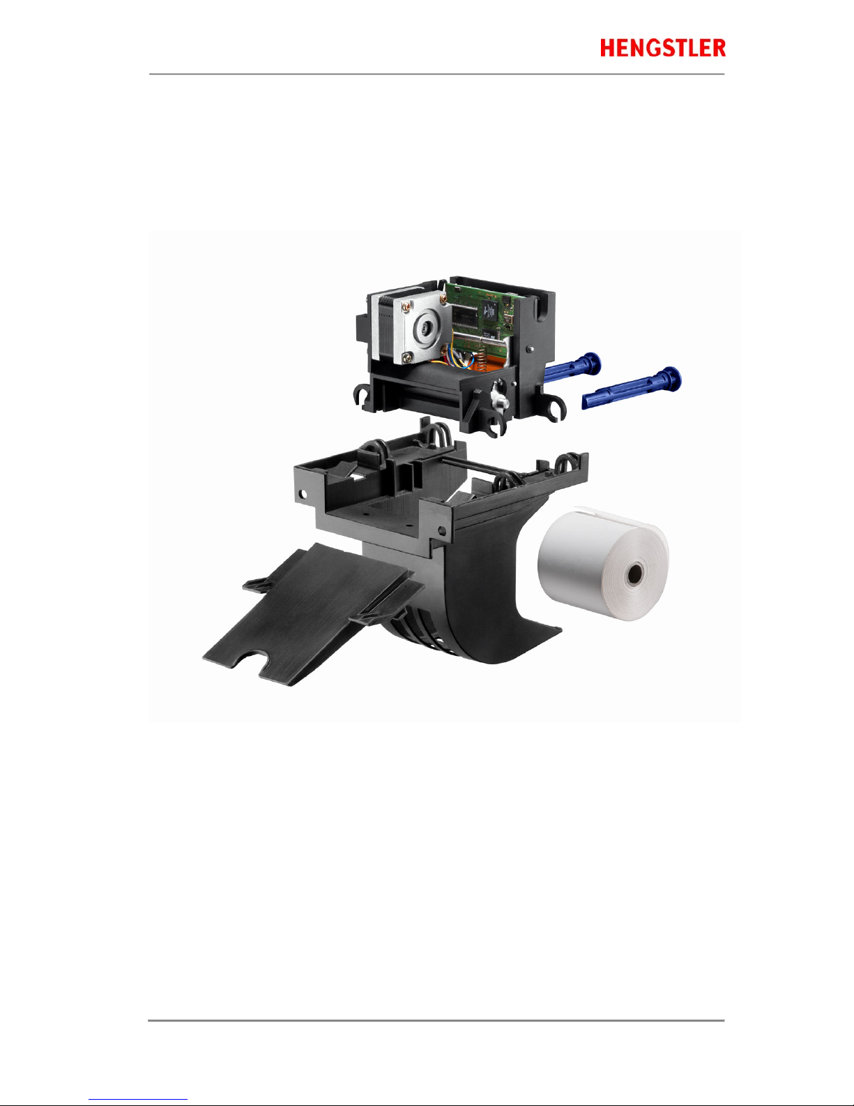
5.2 Replacement of Components
The C-56 thermal printer does not require any servicing. It has been designed such that its main modules
represented in the illustration below can be replaced also by the operational staff aftershort briefing, within less
than 2 minutes. The modules do not require any adjustment. Note that additional care must be taken concerning
wire routing if the optional chute sensor or hardware paper-low sensor areinstalled.
Fig. 7 Modular structure of the C-56 thermal printer with 4 main components
The eject chute is pushed into the guiding supports on the basic unit and cannot be removed when the printer
mechanism is installed. It represents the only access to the printer for the customer. The hinge pins are inserted
into the collars onto thebasic unit in the sense illustrated above and then are pushed against the tilt position.
Only in this position, the printer mechanism can be placed onto the basic unit, and when the hinge pins are
snapped into the operating position, the printer will be locked on the basic unit. The two holes on the front of the
basic unit serve for installing the C-56 thermal printer in vendingapplications etc.

Thermal Printer C-56
Part No. 2 684 019 Rev. No. 4310715 eli page 14 of 17
6.0 Technical Data
6.1 General Data
Dimensions: Height-width-depth HxWxD (in mm): 184.5x 129.5 x 169.5
For opening the printer, a free space of height H = 45 mm and width W = 60 mm
must be provided. Please refer to the dimensional sheets at www.hengstler.com.
Weight: Net approx 0.56 kg
Operating Voltage: a) +24 VDC ±5 %, SELV (EN60950)
Current consumption stand by 0.1 A, operation upto 6 A
Recommended safety fuse: 6 A, delayed-action
b) +12 VDC ±5 %, SELV (EN60950)
Current consumption stand by 0.1 A, operation upto 6 A
Recommended safety fuse: 6 A, delayed-action
UL - Certificate: E174318
Interface: a) Mini USB 1.1 industrial; cable length < 3 meters
Transmission rate: 1.5 MBit/s and 12 MBit/s
Printer graphics driver forWindows XP/7/8/10 and LINUX
USB – interface cable
b) Micro RS232; cable length <3 meters
Communication protocol: Hardware DTR/CTS, None
Baud Rate: 4800, 9600, 19200, 38400, 57600, 115200 (default)
Parity: Off (default), On
Data Bits: 8
Stop Bits: 1 (default), 2
RS232 – interface cable
Noise Level: < 55 dB(A) according to ISO 3744
Operating Conditions: For guaranteed printing quality (limit values in brackets)
Temperature: +5 °C to +50 °C (- 30°C to + 70 °C)
Humidity: 20 % to 80 % (90 %), no condensation
Storage Conditions: Temperature: -40° C to + 85° C
Humidity: 5 % to95 %, condensation not permitted
During storage and storage intransit, leave paper inserted between
thermal printhead and platen
Operating Reliability: Printer mechanism: 100 km of paper, at aprinting density of 12.5% or 100 million
dot pulses
MTTR: 1.5 minutes (module exchange)
All data refer to processing of therecommended paper quality, in atemperature
range appropriate to yield the guaranteed printing quality.

Thermal Printer C-56
Part No. 2 684 019 Rev. No. 4310715 eli page 15 of 17
EMC:
EN55022 - Emission
Warning! The C-56 thermal printer is a class "A" appliance.
It can produce radio interference in residential areas so that the user may be forced
to take adequate remedial measures.
When operating the printer from a DC building power supply, or when the DC
power cable exceeds 3 meters in length, appropriateEMI filters must be used.
EN55024 - EMS Immunity
Electrostatic discharges and burst effects may cause short printing interruptions.
But the automatic recovery function will restorethe original state of the thermal
printing mechanism.
Additional action regarding lightning andovervoltage protection will be needed, if
cables and wires are installed outside of a building.
However, this standard can be met only if original units, components, andcables
are applied and the installation instructions are respected.
External interference caused by ESD or EMI can temporarily cause corrupted
printing or data loss.
6.2 Configuration of the Interfaces
USB 1.1 Interface
Type A
(PC Side) Signal
Name mini-B
(C-56 Side)
1 +5V 1 Note: +5V is not connected on the C-56
2 D + 2
3 D - 3
4 GND 5
Metal housing Shield Metal housing
RS 232 Interface Power supply
8-pin micro
(C-56 Side)
Signal Name
(C-56)
Pin assignment
(CP35 series)
1RxD
2TxD
3CTS
4RTS
5GND
6GND
7GND
8N/C
housingshield
Wiring of the C-56 Serial Cable P/N 0684103
Thermal Printer C-56
Part No. 2 684 019 Rev. No. 4310715 eli page 16 of 17
8-pin micro
(C-56 Side)
Signal Name
(C-56)Connection 9-pin Sub-D
(PC side)
Signal Name
(PC side)
1RxD 3TxD
2TxD 2RxD
3CTS 7RTS
4RTS 8CTS
5GNDN/C 4 (jumpered to 6) DTR
6GNDN/C 6 (jumpered to 4) DSR
7GND 5GND
8N/CN/C 1, 9 N/C
housingshield shell shield
6.3 Paper Specifications
Recommended
Paper Quality:
Thermal papers 50 to 60 g/m2;thermosensitive surface on outside;
see Paper Specification D 684012
Converting: Paper roll
Roll width: 58 to 60 mm (2.28" to 2.36")
Roll diameter: upto 100 mm (4")
Typical: 75 mm (3") or 100 mm (4")
The paper pre-end mark is to be printed on the coated paper side. For further data
regarding the printing of pre-end marks or 'Black Marks' please refer to the Paper
Specifications D 684 012.
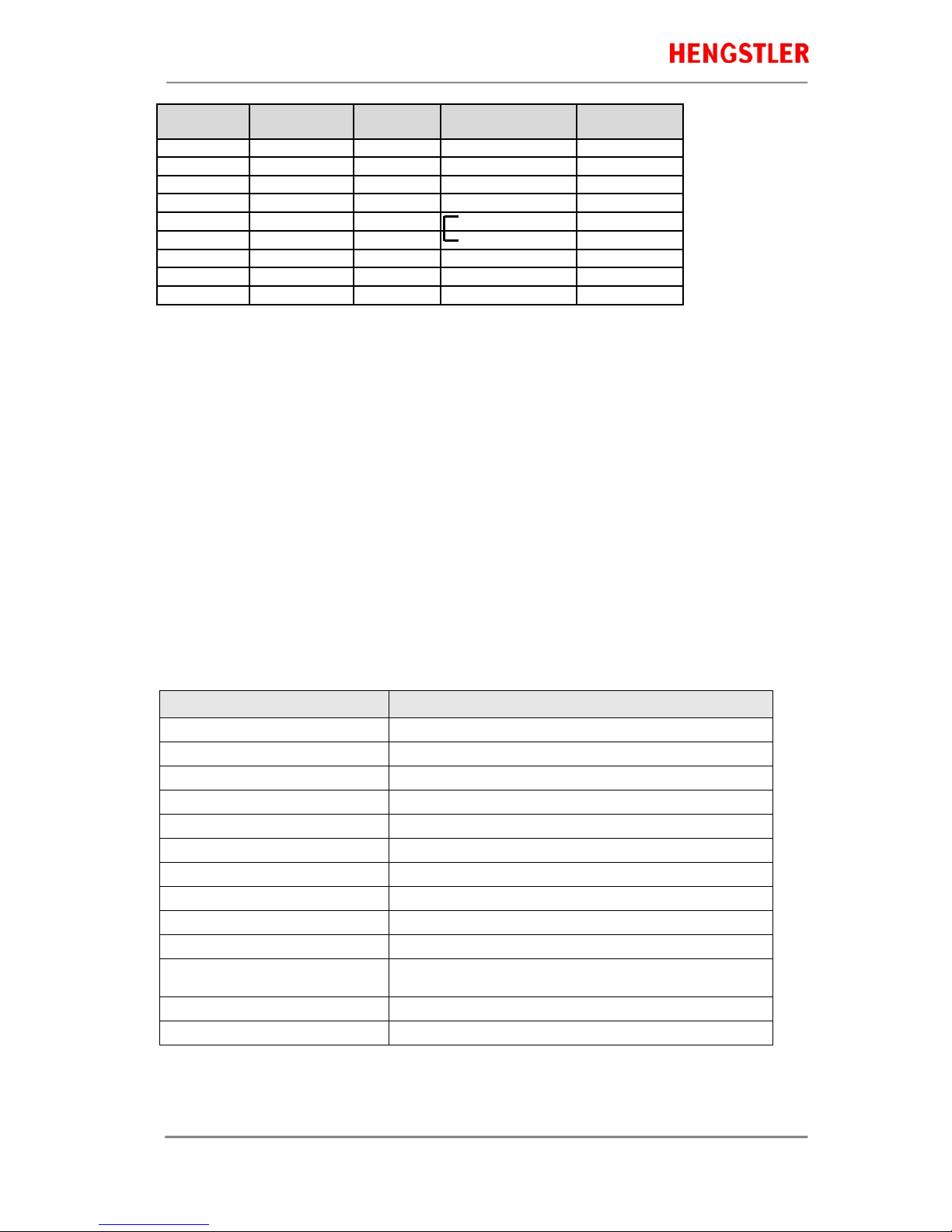
6.4 Data specific to Printing
Designation Specification
Printing method Thermal direct
Number of dots 448
Dot Resolution (horizontal resolution) 8 Dots/mm (203 dpi)
Paper Transport (vertical resolution) 0,125 mm / Dotline (in accordance with thehorizontal resolution)
Max. Printing Width 56 mm
Printing Speed Up to 220 mm / sec (24 VDC) or 160 mm / sec (12 VDC)
Paper Width 58 mm (2,28") to 60 mm (2,36")
Length of document 120 mm up to endless
Maximum ReversePaper Distance 150 mm; longer may leadto paper jams
Chute Sensor Optional chute sensor
Paper Pre-End Detection Printing mark onto the topside
Optional hardware paper pre-end sensor
Printhead Temperature Monitoring Thermistor
Workload Max. 20 documents/ min. (at 120 mm paperlength)
6.5 Order Numbers for Spare Modules

Thermal Printer C-56
Part No. 2 684 019 Rev. No. 4310715 eli page 17 of 17
Thermal Printer mechanism RS232 E2684001
Thermal Printer mechanism USB E2684002
Paper tray (contains 10 pieces) E2684009
Eject chute standard (contains 10 pieces) E2684005
Eject chute short (contains 10 pieces) E1684019
Hinge pin (contains 10 pieces) E2684012
DC power supply cable E1684009
USB Data Cable 0684102
RS232 Data Cable 0684103
Table of contents
Other Hengstler Printer manuals


