Hengstler eXtendo X-56 User manual

Part No. D-684-124 Version 1.10 Mod. No. 4 270919 HW1
Operating Manual
eXtendo®
Thermal Printer Family
Models: X-56 and X-80
E

eXtendo® Thermal Printer Family
Part No. D-684-124 Mod. No. 4 270919 HW1 page 2 of 33
© 2008-2019 by HENGSTLER
Hengstler GmbH has created the text and diagrams contained in this document with care. However, we
cannot accept responsibility for any errors or omissions. Notification regarding any errors and suggestions
for improvement are welcome. We reserve the right to make technical and other changes at any time in the
interest of continual product development.
All information contained in this manual is given without regard to any possible patent protection.
All rights reserved. Reproduction, translation and/or distribution of this document, or extracts thereof, are
permitted only by express authorization from Hengstler GmbH. The Hengstler name, “eXtendo” and the
Hengstler logo are registered trademarks of Hengstler GmbH and the Danaher Corporation. “Windows”and
“Microsoft”are registered trademarks of Microsoft Corporation. Other brand and product names are
trademarks or registered trademarks of their respective companies.
HENGSTLER GmbH
Uhlandstrasse 49
78554 Aldingen
Germany
Tel. +49 (0) 7424-89 0
Fax +49 (0) 7424-89 500
www.hengstler.com

eXtendo® Thermal Printer Family
Part No. D-684-124 Mod. No. 4 270919 HW1 page 3 of 33
Document History
Revision
Date
Init
Status
Description
1.00
2008 Jan 28
CBL
Closed
Initial version
1.01
2008 Mar 31
CBL
Closed
Removed excessive warranty value entries under “Features Selected
at Time of Order”. Corrected figure ref. no. under Wiring, Interfacing.
Removed “Heading” format for word “Serial” under Wiring,
Interfacing.
1.02
2008 June 27
CBL
Closed
Add note re 15 mm minimum paper length. Removed Basic Firmware
option and 130 mm/sec option. Add print speed of 130 mm/sec max.
for 12/10-36 VDC models. Change 10-39 VDC to 10-36 VDC. Change
Printhead Position description to describe three positions.
Troubleshooting section expanded. Black Mark text clarified. Cutter
Operation text clarified. Change sleep mode current spec to 50µA.
1.03
2009 Jan 25
CBL
Closed
Corrected formatting of columns in serial and USB cable pinout
tables. Company logo changed from graphics to text. Add duty-cycle
specification. Add photo of USB and Multivoltage version for
connector positioning. Add description of connectors on gear side.
Modify paper roll holder text. Modify text to match new photos. Add
note re specifications under Power Supply section. Update paper roll
holders in option chart. Added paper roll holder drawing reference.
Add schematic fragment for PVE/Aux. sensor connection. Add
registered trademark symbol (®) to “eXtendo”.
1.04
2009 Feb 20
CBL
Closed
Revise printhead position to two positions (three positions used in
prototypes only). Add “printhead up” status to LED Indicators. Revise
Head Status Sensor to reflect no printing when printhead is up.
Troubleshooting section revised re printhead up operation. Added
printing current specs under Technical Specifications.
1.05
2009 May 15
CBL
Closed
Add section on low current operation. Add FCC Part 15 statement.
Add EN55022, EN55024 statements. Add two “General Information”
points. Add “Function” section. Add cable length limitation to
interface specs. Add warning with photo about damaging cutter
bracket when improperly mounted. Remove “Available soon” from
Linux driver reference in intro. Add fanfold paper reference in “Paper”
section. Add explanation for moving cutter blades manually.
1.06
2010 July 19
CBL
Closed
Add note about no serial handshaking with sleep mode. Add
explanation of chute sensor/partial-cut. Add mounting hole diagram
and expand mounting comments. Update cover photo. Add
installation of paper guide.
1.07
2011 April 21
CBL
Closed
Changed P/N of paper spec document. Correct voltage in print speed
specifications. Increase 24 VDC print speed to 350 mm/sec.
1.08
2012 Aug. 8
CBL
Closed
Add clarifying statement re Class B emissions. Add statement about
sunlight on chute sensor. Add definition of area in line with black
mark where only certain inks may be used. Added drawing of PPE
sensor.
1.09
2015 Oct. 5
Eli
Closed
Serial data cable pinout corrected. 12V and 10-36V options removed
for X-80. Sensor position 3 in X-56 moved left.
1.10
2019 Sep. 12
Eli
Closed
Updating photographs; various corrections, formatting. Added:
polarity information, cutter types, spares, accessories, hints for
grounding and more. Removed multi-volt options.

eXtendo® Thermal Printer Family
Part No. D-684-124 Mod. No. 4 270919 HW1 page 4 of 33
Table of Contents
1. Introduction ......................................................................................................................................6
1.1. Additional Documentation ........................................................................................................6
2. Important Information and Safety Instructions ...................................................................................7
2.1. Systems Specific Safety Instructions and Symbols......................................................................7
2.2. General Information..................................................................................................................7
3. Overview ...........................................................................................................................................8
3.1. Overview of Thermal Printing Technology..................................................................................8
3.2. X-56 versus X-80 ........................................................................................................................8
3.3. Functional View ........................................................................................................................9
3.4. Description of Components and Operation ................................................................................9
3.5. Location of Controls and Connectors .......................................................................................10
3.6. Operation of Sensors and LEDs................................................................................................11
3.6.1. Paper Entrance / Black Mark Sensor.....................................................................................11
3.6.2. Paper Pre-End (Paper Low) Sensor Option ...........................................................................12
3.6.3. LED Indicators.....................................................................................................................14
3.6.4. Printhead Status Sensor......................................................................................................14
3.6.5. Chute/Jam Sensor ..............................................................................................................14
3.7. Graphic Printing vs. Printing with Printer’s Fonts......................................................................15
3.8. Features Selected at Time of Order ..........................................................................................16
5. Installation......................................................................................................................................17
5.1. Unpacking ..............................................................................................................................17
5.2. Function.................................................................................................................................17
5.3. Mounting Printer.....................................................................................................................17
5.4. Installing Paper Guides............................................................................................................18
5.5. Wiring.....................................................................................................................................19
5.5.1. Power.................................................................................................................................19
5.5.2. Data Interfacing ..................................................................................................................19
5.6. Paper Supply ..........................................................................................................................21
5.6.1. Hengstler Paper Roll Holders...............................................................................................21
5.6.2. Designing Your Own Paper Roll Holder.................................................................................21
5.7. Power Supply Specifications ...................................................................................................22
5.8. Electrical Design Aspects .........................................................................................................22
6. Operation........................................................................................................................................23
6.1. Loading Paper ........................................................................................................................23
6.2. Printhead Position Control ......................................................................................................23
6.3. Paper Advance Wheel..............................................................................................................23
6.4. Print Speed.............................................................................................................................24
6.5. Cutter Operation.....................................................................................................................24
6.5.1. Partial Cut with Chute Sensor ..............................................................................................24
6.6. eXtendo® Digital Tools.............................................................................................................25
7. Low Current Operation ....................................................................................................................26
7.1. Print Speed.............................................................................................................................26
7.2. Graphics/Bar Codes ................................................................................................................26
7.3. Inverse Printing.......................................................................................................................26
7.4. Dot History Factor...................................................................................................................26
7.5. Multi-Strobe Factor .................................................................................................................26
7.6. Print Density Adjustment.........................................................................................................26
8. Troubleshooting..............................................................................................................................27
9. Maintenance....................................................................................................................................27
10. Repair and Support.....................................................................................................................27
11. Buying Paper ..............................................................................................................................28
11.1. Sourcing Paper .......................................................................................................................28
11.2. Converting Paper ....................................................................................................................28

eXtendo® Thermal Printer Family
Part No. D-684-124 Mod. No. 4 270919 HW1 page 5 of 33
11.3. Black Mark Sensor Locations ...................................................................................................28
12. Technical Specifications..............................................................................................................30
12.1. General Specifications (X-56 and X-80) .....................................................................................30
12.2. X-56 Specifications..................................................................................................................31
12.3. X-80 Specifications..................................................................................................................31
12.4. Electromagnetic Compatibility ................................................................................................32
12.4.1. FCC Part 15 Class B Device...............................................................................................32
12.4.2. EN55022 –Emissions.......................................................................................................32
12.4.3. EN55024 –Electromagnetic Susceptibility........................................................................32
13. Spare Parts and Accessories ........................................................................................................33
eXtendo® Thermal Printer Family
Part No. D-684-124 Mod. No. 4 270919 HW1 page 6 of 33
1. Introduction
Thank you for selecting the Hengstler eXtendo® Thermal Printer! We are proud of this feature-rich product,
which was designed using all our expertise and experience, and we are confident that you will be pleased
with the advanced features and outstanding performance.
This Operator Manual is designed to help you with the proper installation, connection to your host
computer system and start-up of the eXtendo® thermal printer system. All necessary details will be
explained in the following sections. Please read this manual carefully before using the printer. If you have
any further questions, please do not hesitate to contact us.
The eXtendo® thermal printer family does not require any servicing and is intended primarily for printing
and cutting documents and receipts from continuous thermal paper. The X-56 version is for narrower paper
(49 –60 mm), while the X-80 handles wider paper (60 –86 mm). Various paper cutters are available to handle
a wide range of paper stocks up to 250 g/m² and more. Powerful motors allow the use of large paper rolls to
maximize time between paper replenishment. If documents are to be printed on preprinted forms or with a
predetermined length, 'Black Mark' control is available. The horizontal and vertical print density is 203 dpi
so that graphics, such as logos etc. can be printed with good quality.
The eXtendo® printer family has been designed for use in a wide variety of applications, including ticketing,
parking, banking, transit, reverse-vending, kiosk, car wash, fuel dispensing, and vending applications. In
order to provide the optimal cost/benefit ratio, the eXtendo® family of printers allows you to choose and buy
only the features that you need for your application! This extreme customization insures that you have just
the right amount of printer for your task; not too much, and not too little.
Available in both USB and Serial (RS-232) configurations, the eXtendo® printer family is one of the most
versatile we’ve ever produced! Driver software is available that supports Windows and Linux operating
systems. In addition, the printer can also be operated directly in ASCII mode through ESC sequences a
detailed description of which can be found in the eXtendo® Emulation Command Set Reference.
We’re glad you chose the eXtendo® thermal printer family. Once you’ve used it, we’re sure you will be, too!
1.1.
Additional Documentation
1
Document No.
Description
D 684 112
eXtendo® Emulation Command Set Reference
D 684 128
eXtendo® Paper Specification
D 684 090
D 684 098
X-56 Dimensional Drawing –Twincut Cutter
X-56 Dimensional Drawing –Rotary Cutter
D 684 091
D 684 099
X-80 Dimensional Drawing –Twincut Cutter
X-80 Dimensional Drawing –Rotary Cutter
D 684 152
D 684 154
100 mm Paper Roll Holder Drawing
150 mm Paper Roll Holder Drawing
1
All listed documents can be found in the download area on our webpage under Thermal Printers. If any of these are
missing, please contact our technical support (section “
10 Repair and Support”
).

eXtendo® Thermal Printer Family
Part No. D-684-124 Mod. No. 4 270919 HW1 page 7 of 33
2. Important Information and Safety Instructions
Hengstler GmbH accepts no liability for any damages, direct, indirect or consequential, arising from
improper use of this thermal printer, and, in particular, due to non-compliance with this operating manual
or any other available documentation or due to improper handling or maintenance. Should Hengstler
GmbH choose to make technical documentation available, this does not imply any authorization, implied or
stated, for the making additions, repairs or modifications to this printer.
This documentation may not be copied, nor shall its contents be disclosed or used commercially unless
such use has otherwise been explicitly agreed to by a duly authorized Hengstler representative in writing.
The user is responsible for proper handling and installation of this printer. The printer should only be
shipped in its original packing.
2.1.
Systems Specific Safety Instructions and Symbols
The following symbols on the system and in the manual remind you to follow the relevant
safety instructions:
General warning for cases where the user or a service person may be in danger.
General notes and hints for operating the system safely.
Cross Reference
2.2.
General Information
Hengstler GmbH accepts no liability for the safe operation of the eXtendo® thermal printer family
unless Hengstler original products are used exclusively and the following instructions and
recommendations are heeded.
If unauthorized persons perform any repairs or modifications to the printer mechanism
and the controller, HENGSTLER will not accept any liability and the guarantee shall be
void.
Unapproved types of thermal paper may dramatically reduce the life of the print head and
may cause the guarantee to expire. For pre-printed thermal paper make sure that only
appropriate inks are used. Details can be found in the Hengstler Paper Specifications
document D 684 122.
The DC power connector must not be plugged in or disconnected under load in order to
avoid damage to the electrical components and the thermal printhead.
Avoid strong vibration, shock and impact since they may damage or destroy sensitive
electronic and mechanical components. Do not touch the surface of the printer control
board in order to prevent static electricity from damaging sensitive components.
This thermal printer must not be used near to high-frequency apparatus or strong
magnetic fields in order to prevent undefined magnetic disturbance.
Do not make any attempts to service this printer (e.g. change paper) while the printer is
printing.
Installing or uninstalling the printer must only be done while using adequate ESD protection.

eXtendo® Thermal Printer Family
Part No. D-684-124 Mod. No. 4 270919 HW1 page 8 of 33
3. Overview
3.1.
Overview of Thermal Printing Technology
A brief overview of thermal printer technology might be helpful to understand how the eXtendo®
thermal printer family works. In most direct thermal printers, paper is fed over a soft, rotating
platen and under the thermal printhead. The platen acts as a roller to advance the paper at the
same time it acts as a surface against which the spring-loaded printhead presses the paper to
insure good thermal conductivity. Circuitry in the printer determines which heating elements to
activate (“fire” or “burn”) to form the next row of dots on the paper.
The thermal paper is coated with several compounds. At room temperature, these compounds are
white in color and do not react with each other. The heat from the thermal printhead acts as a
catalyst in the areas where the small printhead dots are fired, causing these compounds to react
with each other and form a new compound which is a contrasting color, usually black. The platen
then advances the paper to the position of the next dot row, and the process is repeated.
You may note immediately several of the advantages of thermal printing. First, since the printing is
done with heat, there is no noise from the printing process itself. Thermal printing is inherently
quiet compared to most other technologies, such as impact dot matrix. Also, there is only one
moving element in the thermal printer: the platen. This provides increased reliability and life when
compared to other technologies.
3.2.
X-56 versus X-80
The X-56 and X-80 thermal printers are based on a single design concept and share many
components. The difference between them is primarily in the width of paper that they will print and
cut. The X-56 handles paper of between 49 and 60 mm in width, while the X-80 accepts paper from
60 to 86 mm wide. Narrower paper than the widest specified above is accommodated by the use of
paper guides to provide additional positional guidance.
This causes one specific minor difference between the two printers. The maximum paper width the
X-56 will accept is 60 mm, and paper guides are not needed for paper in this width range. 58 mm
and 60 mm paper widths are very common, and are considered standards. Paper guides are not
needed to handle these two paper widths.
eXtendo® Thermal Printer Family
Part No. D-684-124 Mod. No. 4 270919 HW1 page 9 of 33
The X-80 has a maximum paper width of 86 mm. While 86 mm wide paper may sometimes be used,
the most common larger paper widths are 80 mm and 82. 5 mm (3¼ inches). These do require a
paper guide to use. This is why the X-80 is always shipped with paper guides, since they are needed
for the most common paper widths.
3.3.
Functional View
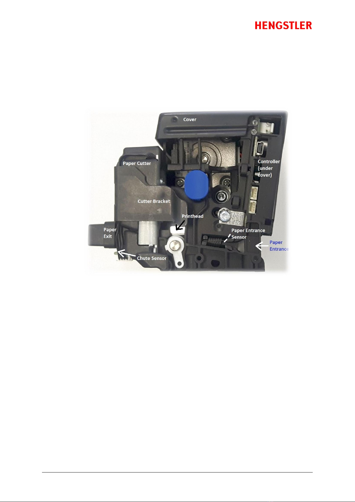
Figure 1
3.4.
Description of Components and Operation
There are several key components or modules to the eXtendo® family of thermal printers (Fig. 1).
The thermal printhead is positioned above the platen. The platen acts as a roller to advance the
paper at the same time it acts as a surface against which the spring-loaded printhead presses the
paper to insure good thermal conductivity. The interface, motor used to turn the platen, sensors,
printhead, and paper cutter are all connected to the controller, which controls all these
components to function at the proper time and which also communicates to the host. The cutter
separates the paper from the paper roll when instructed to do so. Several sensors monitor progress
as the printed document is created. All these items are mounted in a conductive plastic housing to
discharge any static and to provide electrical noise shielding.
The paper chute is a short chute protruding from the front of the printer. It snaps in and out without
tools. The paper chute should be present for most normal printing applications, but it should be
removed for applications where the printed document is expected to fall freely into a chute or other
pathway. In these cases, the chute may interfere with the free fall of the printed document.
The paper entrance sensor detects if paper is approached in the entry area. The controller causes
the motor to turn the platen to draw paper into the printer. As soon as the paper reaches the
platen, the paper is pulled under the printhead and printing can begin.

eXtendo® Thermal Printer Family
Part No. D-684-124 Mod. No. 4 270919 HW1 page 10 of 33
While printing, the paper continues to advance and enters the paper cutter, where it passes
between the cutter blades and out the print chute and passes the chute/jam sensor. Once printing
is completed, the paper is advanced and a command sent to the cutter to cut off the paper. The
paper then retracts to a park position to avoid wasting the paper between the printhead and cutter.
When the printer runs out of paper, the entrance sensor detects the fact. The controller then
immediately stops printing and backs the paper up so it protrudes from the back of the printer. This
is to allow the operator to raise the printhead, remove the partially printed document, and lower
the printhead before loading a new roll of paper. If this were not done, it would be possible for
short pieces of paper to remain in the paper path without the operator’s knowledge, eventually
causing an obstruction and a paper jam.
The chute/jam sensor located at the paper exit monitors whether there is paper in the chute. A
more detailed description of this sensor can be found in chapter 3.6.5.
3.5.
Location of Controls and Connectors
The following figures below show the locations of connectors, indicators and controls on the
eXtendo® series.
Figure 2 shows a USB version of the eXtendo® but also shows the alternative serial connector
when using a printer with RS232 serial interface.
Figure 3 shows the upper portion with details about the polarity of the power connector and
cable.
Figure 4 shows the opposite side of an eXtendo®, showing the Paper Advance Wheel and the
Paper Low and Auxillary Sensor connectors.
Please note that the Paper Pre-end/Paper Low Sensor connectors are optionally duplicated on the
wheel side of the printer to make connection convenient regardless of which side of the printer
might be near the cabinet side wall.
Figure 2

eXtendo® Thermal Printer Family
Part No. D-684-124 Mod. No. 4 270919 HW1 page 11 of 33
Figure 3
Figure 4
3.6.
Operation of Sensors and LEDs
3.6.1. Paper Entrance / Black Mark Sensor
The basic function of the paper entry sensor in the paper entrance area has been described
above. But the same sensor is also used to detect Black Marks. Black Marks are blackened
areas placed on the paper during the converting process. They are generally used, in
conjunction with appropriate printer commands, to advance the paper to a specific
position after each print job. One common reason for this is to so that preprinted
information is properly located with respect to information printed by the printer itself, for
example, printing inside a preprinted box. Black marks can be located on the thermally
coated side of the paper (where printing takes place) or on the back of the paper,
depending upon the location of the sensor.
The eXtendo® series of printers is designed to allow for numerous Paper Entrance/Black
Mark sensor locations during manufacturing (The location of this sensor cannot be
changed once the printer is built). Also, two different sensor types can be used. The most

eXtendo® Thermal Printer Family
Part No. D-684-124 Mod. No. 4 270919 HW1 page 12 of 33
common is the reflex or reflective sensor, where the light source and detector are located
on a single chip. Basically, the light strikes the white paper surface and reflects back into
the sensor. If enough light reflects to activate the sensor, the printer concludes that paper
is present. If there is not enough light reflected, the printer assumes that this area is black,
meaning the printer is on a black mark or the printer is out of paper. There are six (6)
different possible positions for this sensor in the X-56 and ten (10) in the X-80. Half of these
positions sense the coated side of the paper, while the other half sense the back of the
paper. The positions of these sensors are detailed in the Paper section of this document.
The eXtendo® can also use a through-beam sensor in OEM applications. This type of sensor
has a light source on one side of the paper and the detector on the other side of the paper.
When the light is blocked and cannot reach the detector, the printer concludes that paper
is present. When the light does reach the sensor, the printer concludes that there is no
paper present.
The through-beam sensor can also be used in a manner similar to a Black Mark sensor.
Instead of a Black Mark, a hole is used in the paper. The through-beam sensor is located on
the centerline of the paper path. This is the only location it may use.
3.6.2. Paper Pre-End (Paper Low) Sensor Option
When ordered with the Paper Pre-End Sensor option, the eXtendo® will be shipped with a
paper pre-end sensor to be mounted by the customer. The sensor is a reflex type, meaning
that it senses paper by bouncing light off the paper and detecting its reflection. The sensor
is equipped with a 300 mm long cable to allow flexible mounting by the customer, and the
sensor itself is mounted on a small printed circuit board with a hole to be used for
mounting it. Simply mount the sensor where it will detect paper low (it is often mounted
facing the side of the paper roll, so that as the diameter of the paper roll decreases, it
eventually loses the reflection of the light and changes state), and plug the PPE sensor into
the upper sensor connector on the control board. While the exact distance of the sensor
from the paper varies from application to application, it is typically 2-5 mm for optimal
sensing.
If the printer with a paper roll holder is ordered, the sensor comes pre-mounted to the
paper roll holder and with the sensor connector plugged into the eXtendo® controller
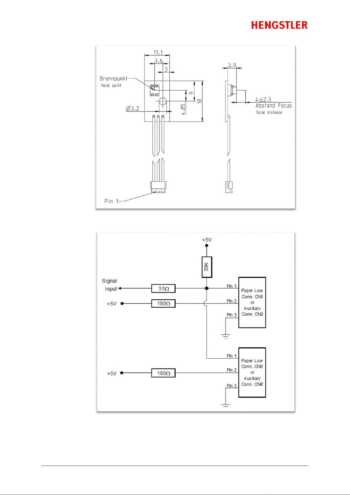
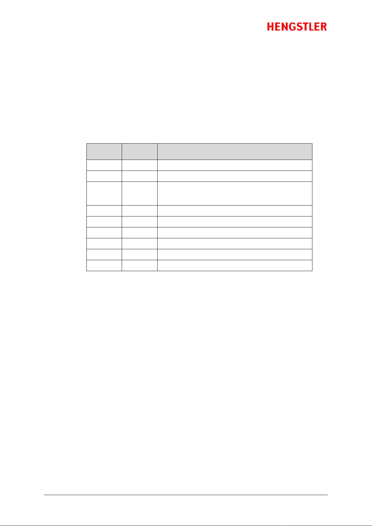
board. Figure 5 below shows the PPE sensor itself, while Figure 6 is the input circuit to the
Paper Pre-End (Paper Low) input.
The lower sensor connector is for an Auxiliary Sensor, which can be mounted as desired by
the customer. The status of this sensor or it input voltage reading will be reported when
the printer’s status is requested via the interface. The Auxiliary Sensor connector is located
below the Paper Pre-End (Paper Low) Sensor connector.
Figure 6 shows the input circuit for these sensor connectors (Fig. 6 represents the circuit for
either the Paper Low or Auxiliary Sensor; these two inputs are wired identically). Please
note that each sensor input can have two connectors, a second one on the wheel side of
the printer. The Paper Pre-End (Paper Low) Sensor connectors are designated CN6 and
CN6’, while the Auxiliary Sensor connectors are CN8 and CN8’.
Note: Only one connector of each pair (for example, CN6 and CN6’) should be connected at
one time.
eXtendo® Thermal Printer Family
Part No. D-684-124 Mod. No. 4 270919 HW1 page 13 of 33
Figure 5 –Paper low sensor
Figure 6 –Sensor Input Circuit
eXtendo® Thermal Printer Family
Part No. D-684-124 Mod. No. 4 270919 HW1 page 14 of 33
3.6.3. LED Indicators
There are two LED indicators in the eXtendo® series printers, located as shown in Fig. 2 and
Fig. 3. The upper LED is red, and the lower one is green. These LEDs are used to signal
various status information concerning the eXtendo® printer. There are several flashing
speeds used in the printer LEDs. These are:
Slow: 0.5 Hz (LED is “on” for one second and “off” for one second)
Medium: 5 Hz (“on” for 100 ms and “off” for 100 ms)
Flicker (F): 10 Hz (“on” for 50 ms and “off” for 50 ms)
0: (off for 1 second)
1: ( on for 1 second)
Green
LED
Red
LED
Meaning
Slow
Off
Paper is loaded. Normal operation. Printer ready.
Medium
Off
Out of paper
Flicker
On
Data upload in progress (fonts, images, firmware, not
normal data communication). Do NOT disconnect or
power the printer off!
F 0F
On
Printhead raised, printer stalled or over voltage
F 010F
On
Paper error
F 01010F
On
Cutter error
Off
On
Boot failure
Flicker
Flicker
Initialization error
On
On
System “hung” during initialization
Please note that much more detailed information concerning the printer’s current state
and sensor conditions can be obtained by requesting the printer’s status ( eXtendo®
Emulation Command Set Reference D 684 112) or by using the eXtendo® Diagnostic Tool.
3.6.4. Printhead Status Sensor
An additional Head Status Sensor is used to determine whether the printhead is in the up
(do not print) or down position (ready to print). Normally, most of the heat generated by
thermal printing is transferred to the paper being printed and so is removed from the head
as the paper advances. When the printhead is in up position no printing or paper loading is
possible.
The output of this sensor as well as the current printhead temperature is also available
from various query functions.
3.6.5. Chute/Jam Sensor
The chute/jam sensor continually monitors whether there is paper in the chute, and can be
read via the Status function. This function is often used in conjunction with the host’s
peripherals to signal the user when a printout has not been taken. Examples where this is
important include when the information is confidential, or the printout can be redeemed
for cash or items of value. This function can also be used to prevent the host from sending
a new print job until the printout from the previous print job has been removed.
Additionally, the chute/jam sensor is monitored while first printing after a cut. After a cut,
the printer “knows” where the end of the paper is. As printing takes place, the printer also
“knows” when the edge of the paper should reach the sensor. If the paper does not reach

eXtendo® Thermal Printer Family
Part No. D-684-124 Mod. No. 4 270919 HW1 page 15 of 33
the sensor when expected, the printer assumes that a paper jam has taken place and
signals this fact via the Status command.
Note: Care must be taken when mounting the eXtendo printers to insure that the sensor is
not exposed to direct sunlight. The multiple wavelengths of sunlight can cause false
readings from this sensor. Therefore, always shield the chute and sensor from direct
sunlight by the use of chutes, shrouds, covers and similar techniques.
3.7.
Graphic Printing vs. Printing with Printer’s Fonts
One area that causes frequent confusion with regard to printers in general is that of graphic
printing versus printing using the printer’s internal fonts. An explanation here may help clarify this
and make application of the eXtendo® easier for you.
All printers contain a set of commands that will cause the printer to perform different functions (For
the eXtendo® family of thermal printers, these commands are documented in the eXtendo®
Emulation Command Set Reference, p/n D 684 112). The functions are very diverse and there are no
standards for what these functions may be. This allows printer manufacturers to innovate and build
unique features into their products. These commands are often referred to as the printer’s “Native
Commands”.
A printer’s Native Commands are of many different types, but a few are of particular interest to us
here. One is the family of commands for printing graphics. It is these commands that allow pictures
and other graphic images of any type to be printed.
Another family of commands of interest to us here is the text commands. These commands involve
printing text in response to ASCII data sent to the printer. The printer itself contains one or more
character sets. In these character sets, one printable character corresponds to one ASCII character.
There are also commands for positioning and modifying the printout from these character sets,
such as tab and indent commands and commands to enlarge the internal characters by some
factor.
When printing from the internal character sets (we’ll call that “ASCII printing” here for
convenience), characters are sent to the printer and the corresponding characters from the
character set are printed. This has both advantages and disadvantages. The biggest advantage is
that the host need only send one character per printed character. So if 40 characters are being
printed on a line, for example, only 40 bytes of data (plus any overhead for formatting, indenting,
etc.) need be transmitted over the interface. In other words, you can print a lot of text and need
send only a little data. The downside is a lack of flexibility. In today’s Windows® world, we are all
used to printing exactly what we see on our computer screens, in the same font, size, etc. as we see
it. But with ASCII printing, what will be printed will be based on the printer’s internal character set.
The other type of printing we’ll call “Graphic printing”. This is what happens when you print to an
ink jet or laser printer from your PC. The information displayed on the screen is sent to a print
driver. This print driver, which is unique for each printer, translates what is on the screen as a
graphic into graphic Native Commands to be sent to the printer. Everything printed through a
print driver prints as graphics. It takes a lot more data to transmit graphics than to transmit ASCII.
In our 40 character example, assuming a 12 x 20 pixel character, the eXtendo® X-80 printer would
require 1,600 bytes (80 bytes/dotline * 20 dotlines) to print one “text” line (please note that these
are estimates, and that various compression routines also impact the amound of data bytes).
The advantage of Graphic printing, then, is the ability to print anything; pictures, text, photos, etc.
exactly as you see it on your screen. The disadvantage is that to do so, much more data must be
sent over the interface.
eXtendo® Thermal Printer Family
Part No. D-684-124 Mod. No. 4 270919 HW1 page 16 of 33
If you are doing ASCII printing, you can use USB or a serial interface. Both are fast enough to handle
the smaller amount of data being sent. But if you are doing Graphic printing, USB may be the better
choice due to its higher speed, and serial may increase the time to complete a printout to an
unacceptably long period.
3.8.
Features Selected at Time of Order
One of the strengths of the eXtendo® family of thermal printers is that it allows the designer to
select the features needed, rather than settling for performance less than desired or having to pay
for features that will never be used. The current set of available options is listed below.
Feature Description
Option 1
Option 2
Option 3
Basic Unit
X-56
X-80
Communications
Interface
USB
Serial (RS-232)
Cutter
Twincut, Full and
Partial Cut, up to
120 g/m²
Twincut, Full Cut Only,
up to 160 g/m²
Rotary, Full Cut Only,
up to 250 g/m²
Environmental Range
0 to +50ºC
25% to 80% RH,
non-condensing
-25 to +70ºC
20% to 100% RH
Voltage
24 VDC
12 VDC (only for X-56)
Paper Entry Sensor
Default BM Sensor
location:
Pos. 6 for X-56
Pos. 10 for X-80
(BM = black mark)
BM sensor located at
one of the positions
shown in Figure 13
Through-beam Sensor
in center position
Paper Guides1)
Note: Standard on X-80
Not included
Included
(2 pcs in a little bag)
Paper Roll Holder1)
(including a Paper Pre End
Sensor)
Not included
100 mm roll mounted
on data connector side
100 mm roll mounted
on gear side
150 mm roll mounted
on data connector side
150 mm roll mounted
on gear side
Paper Chute1)
Included
Not included
Paper Pre-End Sensor1)
Not included
Included
(12 inch cable)
Extended Warranty
Not included
3 year warranty
Other warranty
conditions on demand
1)
These components can also be ordered separately as accessories. See section “Spare Parts and
Accessories”.
Due to the wide variety of options possible, it is necessary to be able to identify what features are
included in each printer. Some features, such as the cutter or PPE sensor, are visually obvious.
Other features such as software configuration and extended warranty, are not. Therefore, this data
is stored as a code in each printer when it is manufactured.

eXtendo® Thermal Printer Family
Part No. D-684-124 Mod. No. 4 270919 HW1 page 17 of 33
5. Installation
5.1.
Unpacking
Care should be taken when unpacking your eXtendo® printer to preserve the packing material for
possible future use. eXtendo® packing is specifically designed to protect the printer from damage in
the harsh environment of trucks and aircraft.
Please be sure to use this packing if it ever becomes necessary to reship your eXtendo® unit.
5.2.
Function
Please note that the eXtendo® printer is a module designed to be integrated into a system and to be
operated only as a part of that system, for example, in a kiosk. All technical specifications and
instructions contained in this manual and related documentation must be considered and
complied with in order to achieve successful operation in the completed system.
5.3.
Mounting Printer
The eXtendo® printer is built with four mounting holes for mounting from below, and four holes for
mounting from the side. These holes are molded into bosses which are part of the plastic frame.
Due to the very tough nature of the plastic used for the eXtendo®, we recommend the following
screws for mounting the printer.
Side Mounting Holes: EJOT Delta PT30, max. penetration into the printer 8 mm
Bottom Mounting Holes: EJOT Delta PT40, max. penetration into the printer 8 mm
These screws are available from Hengstler as a “mounting kit” to simplify your sourcing needs. Hole
layouts (viewed from above the printer) for mounting the X-56 and X-80 models with screws from
underneath are shown below. Please refer to the drawings specified in section 1. 1 for more
detailed dimensions and mounting hole locations for mounting from the side.
Figure 7a –X-56 Figure 7b –X-80
Note: The eXtendo® printer is designed with a cutter cover (cutter bracket) that is hinged and can
be tilted down to gain access to the cutter. However, the printer is designed such that this cover can
be tilted down only if the printer is mounted at the edge of a shelf (Fig. 8). Attempting to lower
this cover if the printer is back from the edge on a flat surface will likely damage the cutter cover!
Please be aware of this when selecting your printer mounting location.

eXtendo® Thermal Printer Family
Part No. D-684-124 Mod. No. 4 270919 HW1 page 18 of 33
Figure 8
5.4.
Installing Paper Guides
Depending upon the model and the options ordered, the eXtendo® family of thermal printers may
come with a pair of paper guides. Since the paper guides are only used for certain width papers,
and should not be used with other widths, they are not installed at the factory. Paper guides should
be utilized as follows.
Paper Width Paper Width
No. of Guides X-56 X-80
none 58-60 mm 84-86 mm
one 55-57 mm 81-83 mm
two 49-54 mm 60-80 mm
Use the following procedure to install paper guides. Please note that the cover has been removed
from the printer to make it easier to see the paper guide area.
1. Locate the paper guides in a small bag packed with the printer and remove them. Note that the
slotted, funnel-shaped opening it oriented towards the printer, and that the extended arms of
the paper guide (Fig. 9) should point towards the middle of the printer. The paper guides are
symetrical and can be use on the left and right side equally.
Figure 9
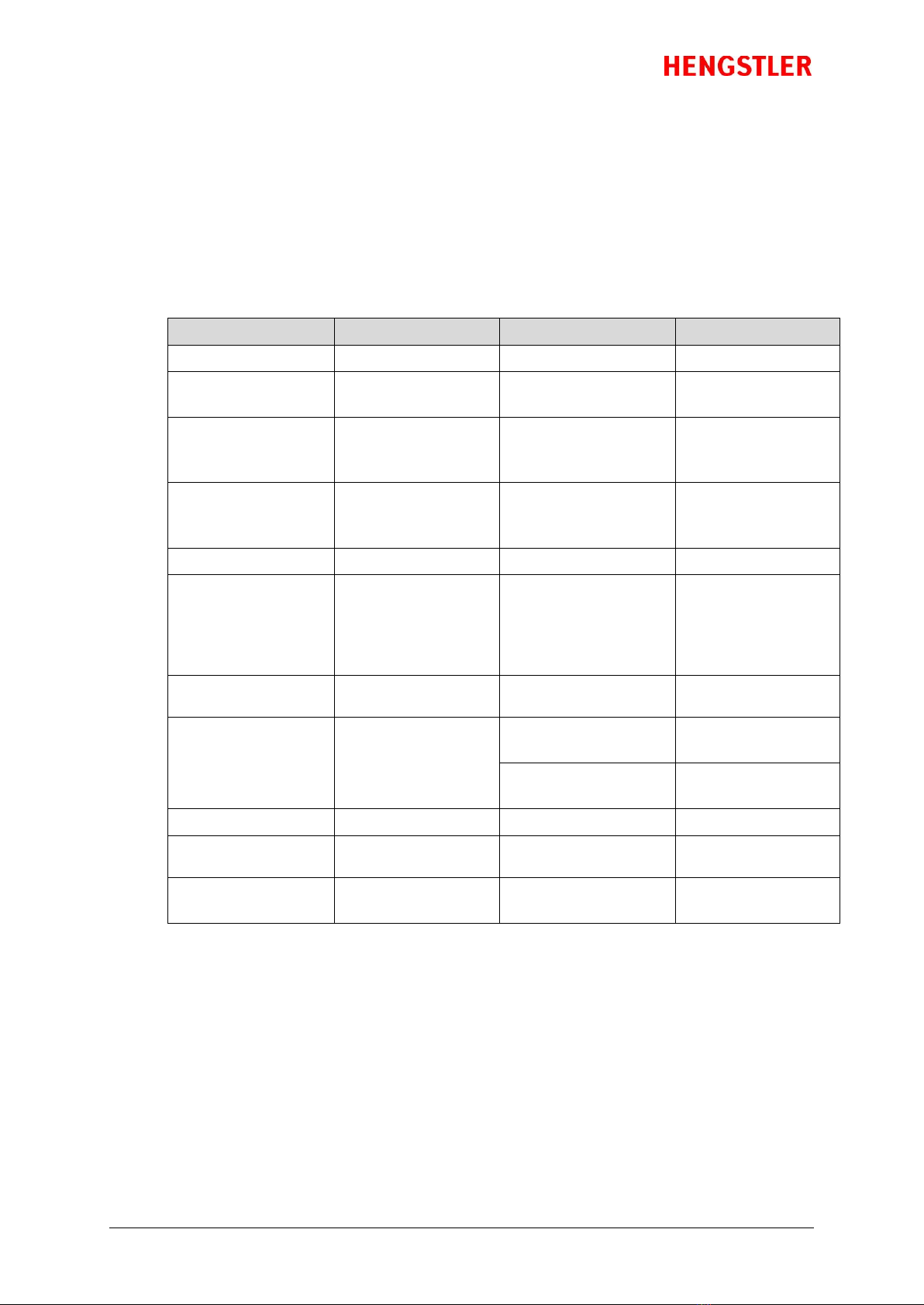
2. Note that the paper guide has four tabs that are intended to engage the printer. Two tabs are at
the end of the arms, and two tabs are near the slotted “funnel”. Locate the slotted area at the
back of the printer (Fig. 10). Position the tabs on the funnel end in the middle of the slotted
area of the side in which you will mount them, making sure to be clear of the gear teeth molded
into the printer, then press down until these two tabs snap into place.
Printer should not be
located further back
from edge than shown to
prevent interference
when pivoting the cutter
bracket
eXtendo® Thermal Printer Family
Part No. D-684-124 Mod. No. 4 270919 HW1 page 19 of 33
Figure 10
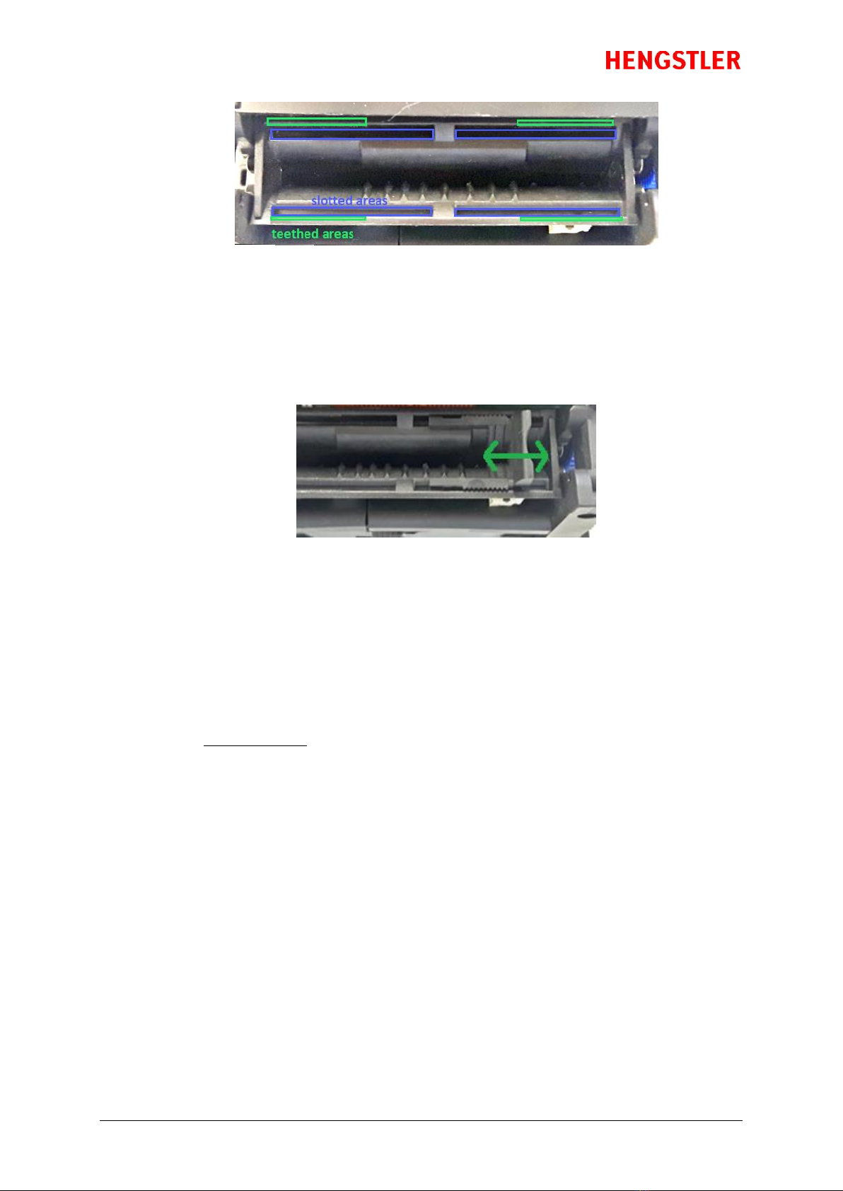
3. Slide the paper guide all the way to the outer edge of the slotted area. Press on first one, then
the other of the arms to snap these two tabs into place.
4. The paper guide is now installed. Push or pull on the end of the paper guide to position it where
desired (Fig. 11). You will hear the paper guide click as it locks into each position.
Figure 11
5.5.
Wiring
5.5.1. Power
Power is connected to the eXtendo® thermal printer via a JST connector. The connector
consists of a JST VHR-2N (RA 3. 96) shell and two SVH-21T-P1. 1 contacts. Wiring is as
follows:
Pin Function
1 0 VDC/GND (-) (blue )wire
2 24 VDC (+) (red wire)
The upper contact on the connector is common; the lower contact is the positive (+)
voltage (Fig. 3).
Note: USB GND and power GND are connected to each other.
5.5.2. Data Interfacing
Serial
The printer is shipped with the following serial settings as default: 115,200 baud, 8 data
bits, one stop bit, no parity, hardware flow control, and host transmission not blocked (this
last feature is intended for use with lower sophistication hosts that cannot read the
eXtendo® printer’s status data. It uses the hardware handshake lines to prevent the host
from sending more data if the printer registers “paper out”).

eXtendo® Thermal Printer Family
Part No. D-684-124 Mod. No. 4 270919 HW1 page 20 of 33
The serial versions of the eXtendo® printer use a JST ZHR-6 connector shell with
JST SZH-002T-P0.5 contacts to make the RS-232 connection. Hengstler can provide a serial
cable for direct connection to PCs with a DB-9 connector on one end (section
13 Spare
Parts and Accessories
). Connections are as follows, should you decide to make your own
connectors.
Serial Pinout
DB-9 female ZHR-6
Pin # Pin# I/O Function (Printer view)
8..........................1 RTS\
7..........................2 CTS\
5..........................3 GND
(internally connected to 0 VDC)
2..........................4 TXD\
3..........................5 RXD\
-- 6 n/c (leave unconnected)
1 n/c
4 jumper to pin 6
6 jumper to pin 4
9 n/c
Shell Earth Ground
Please note that the Hengstler cable is supplied with a flying pigtail on the printer end. This
pigtail is intended to be fastened under the grounding screw, as shown in Fig. 2, to provide
maximum reduction of radiated electrical noise.
For additional protection against accidental cable removal, the cable tie-downs (Fig. 2)
are provided as a point to which you may fasten cables using cable ties (not provided).
USB
The USB versions of the eXtendo® printer employ a standard digital camera USB interface
cable (5 pin Mini-B connector on the printer end) to communicate with the host. Be sure
that the Mini-B connector is fully engaged with the mating connector on the printer. The
other end of the cable plugs into a USB port on the host.
USB Pinout
Pin
Number Signal name I/O Function
1 NC no connection
2 D- I/O Data -
3 D+ I/O Data +
4 NC no connection
5 SGND I/O Signal Gnd
(internally connected to 0 VDC)
Please note that the shell of the USB connector automatically makes a connection to the
earth ground screw as shown in Fig. 2.
Other manuals for eXtendo X-56
2
This manual suits for next models
1
Table of contents
Other Hengstler Printer manuals


