Hengstler XPM 80 User manual
Part No. D 690 019 Version 1.05 Mod. No. 4 051015 Eli1
Operating Manual
XPM 80™
Thermal Printer Family
E

XPM 80™ Thermal Printer Family HENGSTLER
Part No. D 690 019 Mod. No. 4 051015 Eli1 page 2 of 32
© 2008-2015 by HENGSTLER GmbH
Hengstler GmbH has created the text and diagrams contained in this document with care. However,
we cannot accept responsibility for any errors or omissions. Notification regarding any errors and
suggestions for improvement are welcome. We reserve the right to make technical and other
changes at any time in the interest of continual product development.
All information contained in this manual is provided without regard to any possible patent protection.
All rights reserved. Reproduction, translation and/or distribution of this document, or extracts thereof,
are permitted only by express authorization from Hengstler GmbH. The Hengstler name and the
Hengstler logo are registered trademarks of Hengstler GmbH. “Windows” and “Microsoft” are
registered trademarks of Microsoft Corporation. Other brand and product names are trademarks or
registered trademarks of their respective companies.
HENGSTLER GmbH
Uhlandstrasse 49
78554 Aldingen / Germany
Tel. +49 (0) 7424-89 0
Fax +49 (0) 7424-89 500
www.hengstler.com

XPM 80™ Thermal Printer Family HENGSTLER
Part No. D 690 019 Mod. No. 4 051015 Eli1 page 3 of 32
Document History
Revision Date Init Status Description
1.00 2010 Feb 25 CBL Closed Initial version
1.01 2010 Feb 26 CBL Closed Marked “Preliminary”
1.02 2010 Sep 30 CBL Closed “Preliminary” removed
1.03 2011 Feb 10 CBL Closed EN55022 rating changed to Class B.
1.04 2013 Feb 12 CBL Closed
Added figure showing location of paper pre-end pins
within connector, and clarifying text. Removed
redundant paper pre-end text.
1.05 2015-Oct-05 Eli Closed
Serial cable pinout corrected.
Operating temperature spec corrected.

XPM 80™ Thermal Printer Family HENGSTLER
Part No. D 690 019 Mod. No. 4 051015 Eli1 page 4 of 32
Table of Contents
1.Introduction ...................................................................................................................................... 6
1.1.Additional Documentation ....................................................................................................... 6
2.Important Information and Safety Instructions.................................................................................7
2.1.General Information ................................................................................................................ 7
2.2.Systems Specific Safety Instructions and Symbols ................................................................ 7
3.Overview .......................................................................................................................................... 8
3.1.Overview of Thermal Printing Technology .............................................................................. 8
3.2.Functional View....................................................................................................................... 9
3.3.Description of Components and Operation........................................................................... 10
3.4.Location of Controls and Connectors.................................................................................... 11
3.5.Operation of Controls, Sensors and LEDs............................................................................ 13
3.5.1.Dual-Feed Controls ....................................................................................................... 13
3.5.2.Dual-Feed Paper Guides .............................................................................................. 13
3.5.3.Upper and Lower Paper Path Entry Sensors................................................................14
3.5.4.Upper and Lower Paper Path Exit Sensors .................................................................. 14
3.5.5.Paper Entrance / Black Mark Sensor ............................................................................ 14
3.5.6.Head Status Sensor ...................................................................................................... 14
3.5.7.Cutter Sensors .............................................................................................................. 15
3.5.8.Paper Exit Sensor ......................................................................................................... 15
3.5.9.Paper Pre-End (Paper Low) Sensors............................................................................ 15
3.5.10.LED Indicators............................................................................................................... 16
3.6.Graphic Printing vs. Printing with Printer’s Fonts.................................................................. 16
4.Unpacking ...................................................................................................................................... 17
5.Major Options................................................................................................................................. 17
5.1.Barcode Scanner Option.......................................................................................................17
6.Installation...................................................................................................................................... 18
6.1.Function................................................................................................................................. 18
6.2.Mounting Printer.................................................................................................................... 18
6.3.Wiring .................................................................................................................................... 19
6.3.1.Power ............................................................................................................................ 19
6.3.2.Interfacing...................................................................................................................... 19
6.3.3.Paper Pre-End............................................................................................................... 21
6.4.Paper Supply......................................................................................................................... 22
6.4.1.Paper Roll Holder .......................................................................................................... 22
6.5.Power Supply Specifications................................................................................................. 23
7.Operation ....................................................................................................................................... 23
7.1.Loading Paper....................................................................................................................... 23
7.2.Dual-Feed Unit ...................................................................................................................... 24
7.3.Printer Access Control .......................................................................................................... 24
7.4.Print Speed............................................................................................................................ 25
7.5.Cutter Operation.................................................................................................................... 25
7.6.Print Density .......................................................................................................................... 25
7.7.Invalidation ............................................................................................................................ 26
7.8.XPM 80™ Digital Tools .........................................................................................................26
8.Low Current Operation................................................................................................................... 26
8.1.Print Speed............................................................................................................................ 27
8.2.Graphics/Bar Codes.............................................................................................................. 27
8.3.Reverse Printing.................................................................................................................... 27
8.4.Dot History Factor ................................................................................................................. 27
8.5.Burn Time Correction ............................................................................................................ 27
8.6.Multi-Strobe Factor................................................................................................................ 27
8.7.Print Density Adjustment....................................................................................................... 27
9.Troubleshooting ............................................................................................................................. 28
10.Maintenance.............................................................................................................................. 28
11.Repair........................................................................................................................................ 29
12.Buying Paper............................................................................................................................. 29
12.1.Sourcing Paper...................................................................................................................... 29

XPM 80™ Thermal Printer Family HENGSTLER
Part No. D 690 019 Mod. No. 4 051015 Eli1 page 5 of 32
12.2.Converting Paper .................................................................................................................. 29
12.3.Black Mark Sensor Location ................................................................................................. 29
13.Technical Specifications............................................................................................................ 31
13.1.Electromagnetic Compatibility............................................................................................... 32
13.1.1.FCC Part 15 Class B Device......................................................................................... 32
13.1.2.EN55022 – Emissions................................................................................................... 32
13.1.3.EN55024 – Electromagnetic Susceptibility ................................................................... 32
13.2.Printer Drawings.................................................................................................................... 32

XPM 80™ Thermal Printer Family HENGSTLER
Part No. D 690 019 Mod. No. 4 051015 Eli1 page 6 of 32
1. Introduction
Thank you for selecting the Hengstler XPM 80™ thermal printer! We are proud of this feature-rich
product, which was designed using all our expertise and experience, and we are confident that you
will be pleased with the advanced features and outstanding performance.
This Operator Manual is designed to help you with the proper installation, connection to your host
computer system and start-up of the XPM 80™ thermal printer system. All necessary details will be
explained in the following sections. Please read this manual carefully before using the printer. If you
have any further questions, please do not hesitate to contact us.
The XPM 80™ thermal printer family does not require any servicing and is intended primarily for
printing and cutting documents and receipts from continuous thermal paper. The XPM 80™ handles
paper with a width of 55 to 86 mm. A cutter is standard and is integrated into every XPM 80™ print
mechanism. Powerful motors allow the use of large paper rolls to maximize time between paper
replenishment. 'Black Mark' control is available for when documents are to be printed on preprinted
forms or with a predetermined length. Models with horizontal and vertical print density of 203 can be
provided so that graphics, such as logos etc. can be printed with excellent quality.
The XPM 80™ printer family has been designed for use primarily in transit and similar ticketing
applications. Its robust design makes it a natural choice for such heavy-usage.
Equipped with either USB or Serial (RS-232) interfaces, the XPM 80™ printer family is one of the
most versatile we’ve ever produced! Driver software is available that supports the Windows XP and
Linux operating systems. In addition, these printers can also be activated directly through ESC
sequences; a detailed description of the different native commands is contained in the XPM 80™
Emulation Command Set Reference.
We’re glad you chose the XPM 80™ thermal printer family. Once you’ve used it, we’re sure you will
be, too!
1.1. Additional Documentation
Document No. Description
D 690 004 XPM 80™ Emulation Command Set Reference
D 690 005 XPM 80™ Windows®XP Driver Manual
D 690 008 XPM 80™ Linux Driver Manual
D 690 112 XPM 80™ Paper Specification
D 690 021 XPM 80™ Dimensional Drawing

XPM 80™ Thermal Printer Family HENGSTLER
Part No. D 690 019 Mod. No. 4 051015 Eli1 page 7 of 32
2. Important Information and Safety Instructions
Hengstler GmbH accepts no liability for any damages, direct, indirect or consequential, arising from
improper use of this thermal printer, and, in particular, due to non-compliance with this operating
manual or any other available documentation or due to improper handling or maintenance. Should
Hengstler GmbH choose to make technical documentation available, this does not imply any
authorization, implied or stated, for the making additions, repairs or modifications to this printer.
This documentation may not be copied, nor shall its contents be disclosed or used commercially
unless such use has otherwise been explicitly agreed to by a duly authorized Hengstler representative
in writing.
The user is responsible for proper handling and installation of this printer. The printer should only be
shipped in its original packing.
2.1. General Information
Hengstler GmbH accepts no liability for the safe operation of the XPM 80™ thermal printer
family unless Hengstler original products are used exclusively and the following instructions
and recommendations are heeded.
If unauthorized persons perform any repairs or modifications to the printer
mechanism and the controller, HENGSTLER does not accept any liability and the
guarantee shall be void.
Unapproved types of thermal paper may dramatically reduce the life of the printhead
and may void the warranty. For pre-printed thermal paper make sure that only
appropriate inks are used. Detailed can be found in the Hengstler Paper
Specifications document D 689 112.
The DC power connector must not be plugged in or disconnected under load in order
to avoid damage to the electrical components and the thermal printhead.
Avoid strong vibration, shock and impact since they may damage or destroy sensitive
electronic and mechanical components. Do not touch the surface of the printer control
board in order to prevent static electricity from damaging sensitive components.
This thermal printer must not be used near high-frequency apparatus or strong
magnetic fields in order to prevent undefined magnetic disturbance.
Do not make any attempts to service this printer (e.g. change paper) while the printer
is printing.
Installing or uninstalling the printer must only be done while using adequate ESD
protection.
2.2. Systems Specific Safety Instructions and Symbols
The following symbols on the system and in the manual remind you to follow the
relevant safety instructions:
General warning for cases where the user or a service person may be in danger.
General notes and hints for operating the system safely.
XPM 80™ Thermal Printer Family HENGSTLER
Part No. D 690 019 Mod. No. 4 051015 Eli1 page 8 of 32
3. Overview
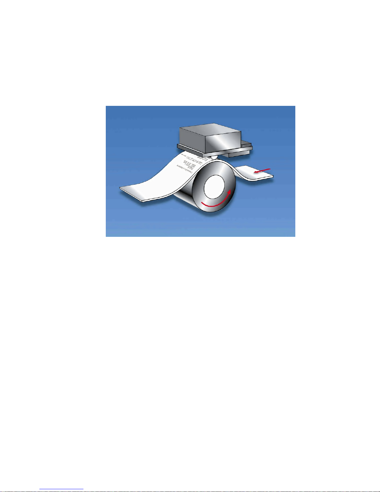
3.1. Overview of Thermal Printing Technology
A brief overview of thermal printer technology might be helpful to understand how the XPM
80™ thermal printer family works. In most direct thermal printers, paper is fed over a soft,
rotating platen and under the thermal printhead. The platen acts as a roller to advance the
paper, and at the same time acts as a surface against which the spring-loaded printhead
presses the paper to insure good thermal conductivity. Circuitry in the printer determines
which heating elements to activate (“fire” or “burn”) to form the next row of dots on the paper.
The thermal paper is coated with several compounds. At room temperature, these
compounds are white in color and do not react with each other. The heat from the thermal
printhead acts as a catalyst in the areas where the small printhead dots are fired, causing
these compounds to react with each other and form a new compound which is a contrasting
color, usually black. The platen then advances the paper to the position of the next dot row,
and the process is repeated.
You may note immediately several of the advantages of thermal printing. First, since the
printing is done with heat, there is no noise from the printing process itself. Thermal printing
is inherently quiet compared to most other technologies, such as impact dot matrix. Also,
there is only one moving element in the thermal printer: the platen. This provides increased
reliability and life when compared to other technologies. Since the chemistry of the thermal
paper itself is what causes the printing to appear, there is no replenishment of ink ribbon, ink
cartridges or toner. This makes thermal printing the least maintenance-intensive of all
common printer technologies.

XPM 80™ Thermal Printer Family HENGSTLER
Part No. D 690 019 Mod. No. 4 051015 Eli1 page 9 of 32
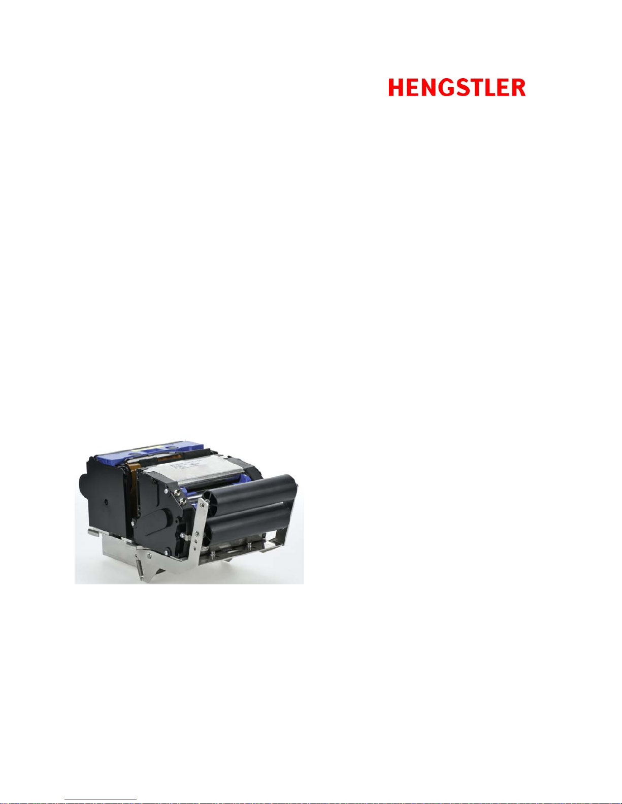
3.2. Functional View
Figure 1
Figure 2

XPM 80™ Thermal Printer Family HENGSTLER
Part No. D 690 019 Mod. No. 4 051015 Eli1 page 10 of 32
3.3. Description of Components and Operation
There are several key components or modules to the XPM 80™ family of thermal printers.
(Please refer to Fig. 1, which shows an XPM 80™ with dual-feed unit, and Fig. 2, which
shows the same printer with the print mechanism open.)
The thermal printhead is positioned above the platen. With the print mechanism closed, the
platen acts as a roller to advance the paper at the same time as it acts as a surface against
which the spring-loaded printhead presses the paper to insure good thermal conductivity.
The interface, motor used to turn the platen, sensors, printhead, dual-feed motors and paper
cutter are all connected to the controller, located in the shallow, metal housing under the
printer, which sends commands and causes these components to function at the proper time.
The cutter separates the paper from the paper supply when instructed to do so. Several
sensors monitor progress as the printed document is created. All these items are mounted to
electrically-conductive mounts to discharge any static and to provide electrical noise
shielding.
When paper is inserted into the dual-feed unit, the entrance sensor detects its presence and
signals the controller. The controller causes the appropriate dual-feed paper advance motor
to turn its roller to draw paper into the dual-feed unit (DFU) and advance it to the printer. The
paper will stop in the printer park position as defined by the XPM Configuration Tool. The
printer is now ready to print. The XPM 80™ will automatically select the last paper inserted
as the paper to be printed. As a result, when one paper path is already loaded and paper is
inserted into the empty paper path, the loaded paper path will reverse the paper and remove
it from the printer, stopping it inside the DFU at the DFU park position. The paper being
loaded will advance to printer park position.
The paper to be printed is selected either by software command or via the Dual-Feed Control
pushbuttons. When the paper path to be printed is selected, the paper presently in the printer
park position is retracted into the dual-feed unit, and the newly selected paper advances into
the printer.
When data is sent to the printer and printing begins, the paper is advanced by the printer
platen as the individual heating elements of the thermal printhead heat as necessary to form
the printout. The selected paper path’s DFU motor advances at the same rate to provide a
smooth, continuous feed. The paper continues to advance and enters the paper cutter area,
where it passes over the fixed cutting blade and out the front. Once printing is completed, the
paper is advanced and a command sent to the cutter to cut off the paper. The paper can then
be retracted to a park position to avoid wasting the paper between the printhead and cutter.
When the printer runs out of paper, the printer entrance sensor detects the fact. How the
printer reacts next depends upon the printer’s settings. One common selection is for the
printout to be invalidated (printed over to make it illegible) as it is retracted out the back of the
printer. Depending upon how the printer has been programmed, it may then switch to the
alternate paper roll (either automatically, via software command, or by use of the Dual-Feed
Control), allowing printing to continue. A replacement paper roll may then be loaded into the
unoccupied paper path of the dual-feed unit.

XPM 80™ Thermal Printer Family HENGSTLER
Part No. D 690 019 Mod. No. 4 051015 Eli1 page 11 of 32
3.4. Location of Controls and Connectors
Please see Figures 3, 4 and 5 below for the location of connectors, indicators and controls on
the XPM 80™ series.
Caution! Care must be taken to avoid injury due to the sharp cutter components
when the print mechanism is open.
Caution! The printhead may be hot from printing that took place shortly before
opening the print mechanism and may represent a burn hazard. Care must be
taken to avoid touching any hot surfaces.
Figure 3 shows a top view of the print mechanism, and identifies the Printer Access Control.
By pulling the recess in the direction shown, access can be gained to the paper path,
printhead, platen and cutter as shown in Figure 2 above. To close the print mechanism,
press down on the black area below the label until the upper print unit snaps closed.
Figure 3
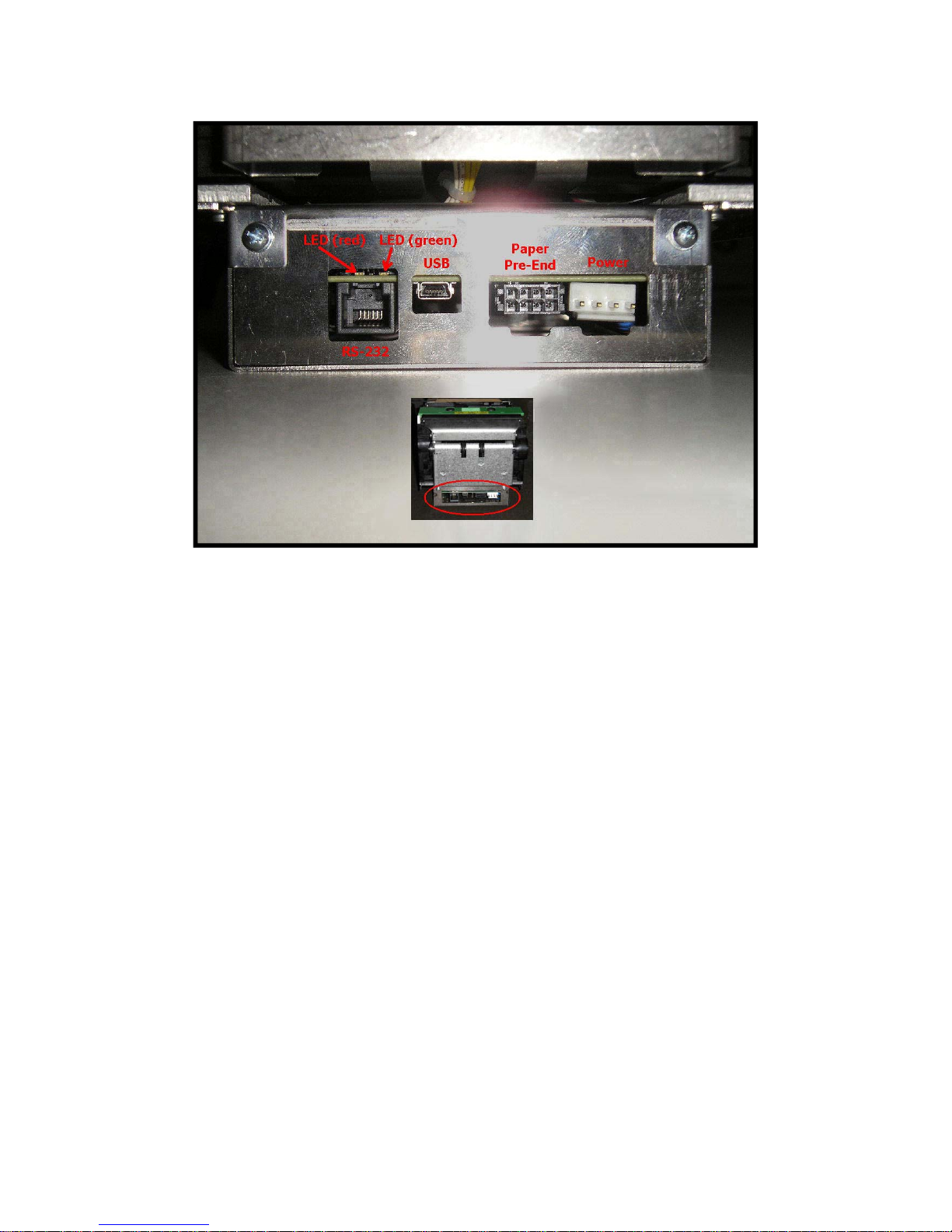
Figure 4 shows the electrical connections for the XPM 80™, which are located beneath the
print mechanism. (This location is referred to as “Side A”.) These consist of the USB
interface, the serial (RS-232) interface, the paper pre-end and weekend sensor inputs for both
paper paths, and the power connection. In some versions of the XPM 80™, these connectors
may be duplicated on the opposite end of the printer under the dual-feed unit. (This location
is referred to as “Side B”.)
XPM 80™ Thermal Printer Family HENGSTLER
Part No. D 690 019 Mod. No. 4 051015 Eli1 page 12 of 32
Figure 4
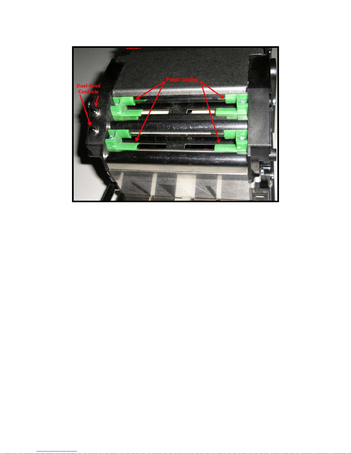
Figure 5 shows the Dual-Feed Unit (DFU). The Dual-Feed Controls are used to manually
select which paper path is to be used, and to eject the paper from that path. The paper path
may also be selected under software control, or automatically when one paper source is
exhausted. The Dual-Feed controls may also be disabled by the printer configuration to
prevent manual manipulation of paper usage.
The Paper Guides can be adjusted by loosening the screws that lock them in position and
sliding them to the proper location. Please note that it is important at all times for the paper
path to be straight. Care must be taken that the paper guides cause the paper to line up
properly with the paper roll holders or the fanfold source. A crooked paper path will increase
the likelihood of paper jams. The paper path should also be centered in the printer to ensure
optimal operation.
All other user-adjustable functions and settings in the XPM 80™ are controlled by the
supplied software tools.
XPM 80™ Thermal Printer Family HENGSTLER
Part No. D 690 019 Mod. No. 4 051015 Eli1 page 13 of 32
Figure 5
3.5. Operation of Controls, Sensors and LEDs
3.5.1. Dual-Feed Controls
Two pushbuttons are mounted on the Dual-Feed unit and control its operation.
(Please note that these pushbuttons can be disabled through the XPM Configuration
Tool to prevent manual intervention with the paper path selection process.) Once
paper is loaded in both paper paths, the controls have the following functions.
Press and release control for selected path: Paper is placed in DFU park
position. (Neither paper path is selected; printer reports out of paper.)
Press and release control for unselected path: Paper for that path is
loaded into printer. Printer reports “ready to print”.
Press and hold control for selected or unselected path: Paper for that
path will eject from back of DFU. Paper will have to be fully removed to clear
paper sensor and then reinserted before it can print. Printer will report out of
paper if that path was the selected paper path.
3.5.2. Dual-Feed Paper Guides
There are two paper guides (one left and one right) for each of the two paper paths in
the DFU. These should be adjusted to properly guide the paper into the DFU. It is
important that the paper be centered in the paper path inlet to ensure the most
reliable, jam-free operation.
To adjust the paper guides, loosen the single screw in each until the guide will slide,
position it in its desired location, and tighten the screw.

XPM 80™ Thermal Printer Family HENGSTLER
Part No. D 690 019 Mod. No. 4 051015 Eli1 page 14 of 32
3.5.3. Upper and Lower Paper Path Entry Sensors
These sensors detect the presence of paper when it is inserted into the upper and
lower paper paths of the Dual-Feed Unit (DFU). The controller uses this information
to load paper and to determine whether paper is present in each of the paper paths.
3.5.4. Upper and Lower Paper Path Exit Sensors
These sensors detect that paper is exiting the DFU, and are part of the jam detection
and control logic system. One function is to determine if paper has been retracted
from one paper path before advancing the paper from the other path into the printer.
3.5.5. Paper Entrance / Black Mark Sensor
There is a sensor in the paper entrance area of the print mechanism that serves
several functions. First, it detects paper entering the print mechanism and signals the
controller to activate the paper advance system. Similarly, when the printer is out of
paper, this sensor detects the fact and signals the printer accordingly.
The same sensor is also used to detect Black Marks. Black Marks are blackened
areas placed on the paper during the converting process. They are generally used, in
conjunction with appropriate printer commands, to advance the paper to a specific
position after each print job. One common reason for this is to so that preprinted
information is properly located with respect to information printed by the printer itself,
for example, printing inside a preprinted box. Black marks must be located on the
back (non-coated) side of the thermal paper.
The XPM 80™ printer is designed to allow for numerous Paper Entrance/Black Mark
sensor locations during manufacturing. (The location of this sensor cannot be
changed once the printer is built.) Also, two different sensor types can be used. The
most common is the reflex or reflective sensor, where the light source and detector
are located on a single chip. Basically, the light strikes the white paper surface and
reflects back into the sensor. If enough light reflects to activate the sensor, the printer
reports that paper is present. If there is not enough light reflected, the printer
assumes that this area is black, meaning the printer is on a black mark or the printer
is out of paper. There are seven (7) different possible positions for this sensor. The
positions of these sensors are detailed in Figure 8.
The XPM 80™ can also use a through-beam sensor. This type of sensor has a
separate light source and detector. The light is transmitted across the paper path into
a prism, which redirects it back across the paper path into the detector. When the
light is blocked and cannot reach the detector, the printer reports that paper is
present. When the light does reach the sensor, the printer concludes that there is no
paper present.
The through-beam sensor can also be used in a manner similar to a Black Mark
sensor. Instead of a Black Mark, a hole is used in the paper. The through-beam
sensor is located in one of seven (7) different possible locations; the centerline
location of the paper path is the default. The positions of these sensors are detailed
in the Figure 9.
3.5.6. Head Status Sensor
An additional Head Status Sensor is used to determine whether the printhead is in
the up (do not print) or down (ready to print position). Normally, most of the heat
generated by thermal printing is transferred to the paper being printed and is removed
from the printer as the paper advances. When the printhead is up, no heat is being
transferred to the paper and the heat remains in the individual dots, allowing them to
overheat if activated repeatedly. Because this may cause permanent damage to the
printer, the XPM 80™ firmware will prevent printing or paper loading if the head is up.

XPM 80™ Thermal Printer Family HENGSTLER
Part No. D 690 019 Mod. No. 4 051015 Eli1 page 15 of 32
The output of this sensor is also available from the Query function. See the
XPM 80™ Emulation Command Set Reference D 690 004 for details on determining
the printhead position and the printhead temperature.
3.5.7. Cutter Sensors
The XPM 80™ uses a “pizza-cutter” style paper cutter. A cutting disk moves from
one side to the other to sever the paper from the roll against a stationary blade.
Sensors are located at the end of travel for this cutter so the controller can detect
where the cutter blade is and determine in which direction it should be moved to cut
the paper.
3.5.8. Paper Exit Sensor
A sensor on the exit side of the print mechanism detects when paper has passed
through the cutter assembly and reached the paper exit.
3.5.9. Paper Pre-End (Paper Low) Sensors
The XPM 80™ has inputs for four sensors indicating Paper Pre-End (Paper Low).
There is one set of sensors (one for the upper paper path and one for the lower) to
detect standard Paper Pre-End (PPE). Connected to appropriately selected sensors,
these will signal via a query through the interface when paper has become low
enough to activate this signal. These two inputs are analog sensor inputs that are
converted to digital signals via analog to digital (A/D) conversion. Therefore, it is
possible to read their analog values and use this information as a measure of sensor
obstruction.
The second set of sensors are also for Paper Pre-End, but are intended for use as
what are commonly called “weekend sensors” (PWE). While the standard PPE
sensors detect when paper has reached some user-defined point where a paper
change will be required shortly, PWE sensors are usually set to signal whether there
is enough paper remaining to make it through the weekend without replenishing the
paper. This is especially useful for installations where the smaller staff that is
available on weekends may not be trained in paper replenishment. The PWE inputs
are direct digital inputs. Since no supply is provided to power an LED-style sensor,
these inputs are best used with a microswitch.

XPM 80™ Thermal Printer Family HENGSTLER
Part No. D 690 019 Mod. No. 4 051015 Eli1 page 16 of 32
3.5.10. LED Indicators
There are two LED indicators in the XPM 80™ series printers, located as shown in
Fig. 4. These LEDs are used to signal some status information concerning the XPM
80™ printer. The following is a partial listing of the information supplied.
There are several flashing speeds used in the XPM 80™ printer LEDs. These are:
Slow: 0.5 Hertz (LED is “on” for one second and “off” for one second)
Medium: 1 Hz (“on” for .5 seconds and “off” for .5 seconds)
Flicker: 10 Hz (“on” for 50 ms and “off” for 50 ms)
Off
On
Red LED Green LED Meaning
Printer operational, paper
available, not printing
Printer operational, paper
available, printing
Printer operational, out of paper
Exchanging data (firmware, fonts,
logos, etc; writing to flash
Printer not operational due to
printhead open, wrong
configuration , wrong voltage or
hard reset
Print mechanism jammed
Cutter jammed
Feed unit jammed
Presenter jammed
Fatal error; SDRAM defective
Fatal error; Board type cannot be
identified
Probable system stall during
initialization phase
Probable system stall during boot
phase
Please note that much more detailed information concerning the printer’s current
state can be obtained by requesting the printer’s status via the interface. Please refer
to the XPM 80™ Emulation Command Set Reference D 690 004 for details.
3.6. Graphic Printing vs. Printing with Printer’s Fonts
One area that causes frequent confusion with regard to printers in general is that of graphic
printing versus printing using the printer’s internal fonts. An explanation here may help clarify
this and make application of the XPM 80™ easier for you.
All printers contain a set of commands that will cause the printer to perform different
functions. (For the XPM 80™ family of thermal printers, these commands are documented in
the XPM 80™ Emulation Command Set Reference, P/N D 690 004.) The functions are very
diverse and there are no standards for what these functions may be. This allows printer
manufacturers to innovate and build unique features into their products. These commands
are often referred to as the printer’s “Native Commands”.
A printer’s Native Commands are of many different types, but a few are of particular interest
to us here. One is the family of commands for printing graphics. It is these commands that
allow pictures and other graphic images of any type to be printed.

XPM 80™ Thermal Printer Family HENGSTLER
Part No. D 690 019 Mod. No. 4 051015 Eli1 page 17 of 32
Another family of commands of interest to us here is the text commands. These commands
involve printing text in response to ASCII data sent to the printer. The printer itself contains
one or more character sets. In these character sets, one printable character corresponds to
one ASCII character. There are also commands for positioning and modifying the printout
from these character sets, such as tab and indent commands and commands to enlarge the
internal character set by some factor.
When printing from the internal character sets (we’ll call that “ASCII printing” here for
convenience), characters are sent to the printer and the corresponding characters from the
character set are printed. This has both advantages and disadvantages. The biggest
advantage is that the host need only send one character per printed character. So if 40
characters are being printed on a line, for example, only 40 bytes of data (plus any overhead
for formatting, indenting, etc.) need be transmitted over the interface. In other words, you can
print a lot of text and need send only a little data. The downside is a lack of flexibility. In
today’s Windows®world, we are all used to printing exactly what we see on our computer
screens, in the same font, size, etc. as we see it. But with ASCII printing, what will be printed
will be based on the printer’s internal character set.
The other type of printing we’ll call “Graphic printing”. This is what happens when you print to
an ink jet or laser printer from your PC. The information displayed on the screen is sent to a
print driver. This print driver, which is unique for each printer, translates what is on the screen
as a graphic into graphic Native Commands to be sent to the printer. Everything printed
through a print driver prints as graphics. It takes a lot more data to transmit graphics than
to transmit ASCII. In our 40 character example, assuming a 12 x 20 pixel character, the
Hengstler XPM 80™ printer would require 1,600 bytes to print one line. (Please note that
these are estimates, and that various compression routines also impact the print speed.)
The advantage of Graphic printing, then, is the ability to print anything; pictures, text, photos,
etc. exactly as you see it on your screen. The disadvantage is that to do so, much more data
(40 times as much data in our example) must be sent over the interface.
As a practical matter, then, it comes down to this. If you are doing ASCII printing, you can
use USB or a serial interface. Both are fast enough to handle the smaller amount of data
being sent. But if you are doing Graphic printing, USB is a far better choice due to its higher
speed, and serial may increase the time to complete a printout to an unacceptably long
period.
4. Unpacking
Care should be taken when unpacking your XPM 80™ printer to preserve the packing
material for possible future use. XPM 80™ packing is specifically designed to protect the
printer from damage in the harsh environment of trucks and aircraft. Please be sure to use
this packing if it ever becomes necessary to reship your XPM 80™ unit.
5. Major Options
5.1. Barcode Scanner Option
XPM 80™ printers can be supplied with an optional barcode scanning feature. The purpose
of this option is to scan preprinted barcodes on the non-coated (back) side of the printout.
The latest scanned barcode is stored in the printer memory and can be read out through the
printer interface via a query command. See the XPM 80™ Emulation Command Set
Reference D 690 004 for details on reading the data from the printer.

XPM 80™ Thermal Printer Family HENGSTLER
Part No. D 690 019 Mod. No. 4 051015 Eli1 page 18 of 32
6. Installation
6.1. Function
Please note that the XPM 80™ printer is a module designed to be integrated into a system
and to be operated only as a part of that system, for example, in a kiosk. All technical
specifications and instructions contained in this manual and related documentation must be
considered and complied with in order to achieve successful operation in the completed
system.
6.2. Mounting Printer
The XPM 80™ printer is designed to be mounted in a vertical orientation (with printout exiting
downward, towards the ground). This vertical orientation allows gravity to help the severed
ticket fall directly into a chute or receptacle of the customer’s design.
Mounting is by means of a series of hooks fabricated into the device to which the XPM 80™
will be mounted. These engage four slots in the printer frame (see Figure 7). Due to the wide
variety of different mounting possibilities and egress systems in the user’s application, it’s not
possible to offer one universal mounting system. Figure 7 shows a sketch and photo of the
mounting slots on the XPM 80. Please see drawing D 690 021 for details.
Figure 7

XPM 80™ Thermal Printer Family HENGSTLER
Part No. D 690 019 Mod. No. 4 051015 Eli1 page 19 of 32
6.3. Wiring
6.3.1. Power
Power is connected to the XPM 80™ thermal printer via a JST connector. The
connector consists of a JST VHR-4N shell and two SVH-21T-P1.1 contacts. Wiring is
as follows:
Pin Function
1 Ground (0 VDC)
2 Ground (0 VDC)
3 +24 VDC
4 +24 VDC
6.3.2. Interfacing
Please note that the XPM 80™ comes with both USB and RS-232 serial connectors
installed. Only one interface is selected for data communication with the printer,
based on how the printer was ordered and configured before shipment.
Also, please note that in some versions of XPM 80™, the USB, RS-232 serial and
PPE connectors may be duplicated on Side B, under the Dual-Feed unit. If this is the
case, only the Side A or the Side B interface connector may be used, not both. See
the section “Paper Pre-End” for details concerning use of two PPE connectors.
RS-232 Serial
The serial versions of the XPM 80™ printer are shipped with the following RS-232
serial settings as default: 115,200 baud, 8 data bits, one stop bit, no parity, hardware
flow control, and host transmission not blocked. (This last feature is intended for use
with lower sophistication hosts that cannot read the XPM 80™ printer’s status data. It
uses the hardware handshake lines to prevent the host from sending more data if the
printer registers “paper out”.)
Note: If the particular XPM 80™ model is equipped with the barcode scanner
option, the RS-232 port is then dedicated to communication with the barcode
scanner and only the USB interface may be ordered for printer
communication.
The serial interface uses a standard RJ-12 connector to make the RS-232
connection. Hengstler can provide a serial cable for direct connection to PCs with a
DB-9 connector on one end. The wiring is as follows, should it be necessary to
fabricate such a cable. Cable length must be limited to under 3 meters.

XPM 80™ Thermal Printer Family
HENGSTLER
Part No. D 690 019 Mod. No. 4 051015 Eli1 page 20 of 32
Serial Pinout
DB-9 Female RJ-12
Pin No. Pin No. I/O Function (printer view)
2 ....................... 1 TXD (transmit data)
3 ....................... 2 RXD (receive data)
7 ....................... 3 RTS (request to send)
8 ....................... 4 CTS (clear to send)
5 no connection
5 ....................... 6 System ground
1 no connection
4 DTR (data terminal ready)
6 DST (data set ready)
9 no connection
Note: Pins 4 and 6 of the DB-9 connector must be jumpered to each other.
USB
The USB versions of the XPM 80™ printer employ a standard USB interface cable (5
pin Mini-B connector on the printer end) to communicate from the host to the printer.
Be sure that the Mini-B connector is fully engaged with the mating connector on the
printer. The other end of the cable plugs into the USB port on the host. The cable
length must be limited to under 3 meters.
Once the printer is connected with the host and the driver is installed, be sure to set
the Port in the driver to the appropriate USB port to match the physical host-side
interface cable port.
USB Pinout
Pin
Number Signal name I/O Function
1 NC no connection
2 D- I/O Data -
3 D+ I/O Data +
4 NC no connection
5 SGND I/O Signal Ground
Table of contents
Other Hengstler Printer manuals


Popular Printer manuals by other brands


Ricoh
Ricoh Aficio GX e3300N user guide

Epson
Epson SpectroProofer Mounter 17" user guide

Kyocera
Kyocera KM-4530 Operation guide

Epson
Epson Stylus Pro 4880 ColorBurst Edition - Stylus Pro 4880... user guide

Brother
Brother HL-L5100DNT Quick setup guide

Star Micronics
Star Micronics TSP1000 Series Product specifications manual


