Herdegen AMPLIPLUS User manual

Créateur d’AutonomieCréateur d’Autonomie
User's manual
AMPLIPLUS BED
2
21/03/2019 Rev.2 (04/12/2019)
Table of contents
Preface
1.General notes
1.1. General information page 3
1.2.Safety instructions
1.2.1. Safety instructions for operators page 3
1.2.2. Safety instructions for users page 3
1.3.Product description page 4
1.4.Technical information
1.4.1.Slats bedframe page 5
1.4.2.Side rails page 5
1.4.3.Electrical adjustment system page 5
1.4.4.Description of materials used page 5
1.4.5.Noise level page 5
1.4.6.Storage page 6
1.4.7.Maximum load capacity and adjustment possibilities page 6
1.4.8.Masses page 6
1.4.9.Dimensions page 6
1.4.10.Standards page 6
2.Assembly and use
2.1.General informations page 7
2.2.Mounting the bed page7
Step 1 Removing side rails and liing pole page 7
Step 2 Connecting the bed page 7
Step 3 Mounting the bed ends page 7
Step 4 Side rails page 8
Step 5 Liing pole page 10
Step 6 Wooden side rails page 11
Step 7 Connecting actuators page 12
Step 8 Remote control page 12
Step 9 Mattress holder page 13
Step 10 Emergency lowering of the backrest page 13
Step 11 Moving the bed around page 14
Step 12 Central locking page 14
2.3. Bed delivered on the transport tray: Assembly steps page 15
2.4. Use of the Transkit page 25
2.5. Use of the handtrolley page 26
2.6. Wall protector page 27
3.Cleaning and disinfecting page 28
3.1. Maintenance
3.1.1. General information page 28
3.1.2.Identication page28
3.2. Cleaning and disinfectants
3.2.1. General information page 29
3.2.2. Cleaning and desinfection page 29
3.3. Troubleshooting page 30
3.4. Test protocol for user page 31
3.5. Exploded view page 31-34
3.6. Shelf life and disposal page 35

3
21/03/2019 Rev.2 (04/12/2019)
Preface
Dear Customer,
Thank you for the condence you have shown in purchasing an HERDEGEN Home Care Bed. This „AMPLI + ®“ Bed is factory
checked for electrical safety and functions and has left our factory in a perfect condition. Please read carefully this instruction
manual. This applies especially to the assembly and disassembly phases but also to daily use. Keep this manual in a safe place for
future reference. It informs the user and operator about the convenient handling of the bed and safe operation.
1.General notes
Operator : retailer, medical store, pharmacy, generaly the company delivering and installing the Home Care bed.
User : qualied staff able to assembly-disassembly the Home Care bed and/or qualied staff able to use it in a correct way.
1.1 General information
*Please read these instructions carefully to avoid damage or incorrect use.
*Clean and disinfect the bed before the rst use. The user shall ensure that the bed is in proper working order and in a perfect
condition, he shall also have read the user‘s manual, before using the bed.
*The Home Care bed AMPLI + ® complies with all requirements of the guidelines 93/42/EWG for medical products. It is classied
as a dynamic medical product of the class I.
*The Home Care bed AMPLI + ® has been checked by an independent test institute. Be aware that an improper use of this device
can lead to damage and/or injury.
*This instruction and operating manual contains safety instructions which must be followed. All persons who work with the Home
Care bed AMPLI + ® must have read those instructions and respect them.
*The use of original Herdegen parts and accessories guarantees the safety and compliance of the product.
*It is strictly forbidden to modify the bed and its accessories.
1.2 Safety instructions
*The nursing bed AMPLI + ® represents the latest technological development at the time of delivery and has bee checked by an
independent testing institute.
*In case of doubt, if the bed appears to be damaged or if you suspect a malfunction, immediately unplug it from wall outlet and mark
it as „DEFECTIVE“.
1.2.1 Safety instructions for operators
Please refer to the „Maintenance Book“ delivered with the bed for specic maintenance programm
*Remember your responsibilities in accordance with the Medical Devices Operator Ordinance -MP Betreib V in order to ensure the
safe operation of this bed without endangering patients, users and third parties.
*Before using the bed, you must inform every user in the safe operation of the Home Care bed according to the safety instructions,
which must be given to the user too.
*The user shall be informed of the location of this instruction manual according to Medical Devices Operator Ordinance -MPBetreibV
9.
*Make user aware of the dangers of improper use of the Home Care Bed, especially regarding the actuators and side rails.
*The Home Care bed should only be operated by properly trained staff.
*Make sure that relatives and potential users are also familiar with the operation of the Home Care bed.
*For long term use we recommend to inspect regularly (every month) the Home Care Bed, to check functions and make a visual
inspection of the bed. For more information about checking which have to be done, please see 4.3
*The bed shall be connected directly to the electrical power. Do not use electrical outlets and extension cords.
*Make sure that the use of other medical or electronic devices (antidecubitus air mattress for example) is possible and ensure the
safe operation of each device.
*Don‘t place several electrical outlets under the bed, as leaking liquids can be a re hazard.
*Make sure that when using external electrical devices such as compressors, lamps..their wires are correctly positionned and don‘t
risk to be crushed, sheared or torn apart when using the moving parts of the Home Care bed.
*In case of troubles or doubt, please ask your retailer or HERDEGEN SAS.
*Make sure that your staff is aware and respect the safety instructions.
1.2.2 Safety instructions for users
*Learn how to use the bed from your specialist.
*This product has a 24-month warranty starting from the date of purchase. The warranty includes all defects and errors caused by
the material and workmanship. Defects and errors caused by improper use and external effects are not included in the warranty.
*Ensure before using the Home Care bed that it is in a perfect condition.
*Ensure that there is enough space available to use the moving elements of the bed in a proper way. No furniture, window frames
should be in the way.
*Make sure that when using external electrical devices such as compressors, lamps..their wires are correctly positionned and don‘t
risk to be crushed, sheared or torn apart when using the moving parts of the Home Care bed.
4
21/03/2019 Rev.2 (04/12/2019)
*Please make sure before connecting the bed that the electrical installation complies with the standard NF C 15 100; if your installation
doesn't comply with this standard, HERDEGEN company would decide to accept or refuse any complains regarding the electical
components of this bed.*In case of troubles or doubt, please ask the operator or HERDEGEN SAS.
*The bed shall be connected directly to the electrical power. Do not use electrical outlets and extension cords.
*Don‘t place several electrical outlets under the bed, as leaking liquids can be a re hazard.
*Unplug the power cable from wall outlet, before moving the Home Care bed around.
*Roll the cable on the support when moving the Home Care bed around so that they are not crushed or squeezed.
*Check the power cable regularly for damages (crushed, bare, sheared, porous..) and particularly :
1/after every mechanical strains(for example : rolling over the cables).
2/after having moved the Home Care bed and before pluging in the power cable.
3/every month in a normal use.
*Regularly check the cable strain relief, it must be in perfect condition.
*Don‘t store anything under the bed.
*Lower the Home Care bed to its lowest position when leaving the patient unattented, thus you reduce the risk of injuries when the
patient leaves-enters the bed.
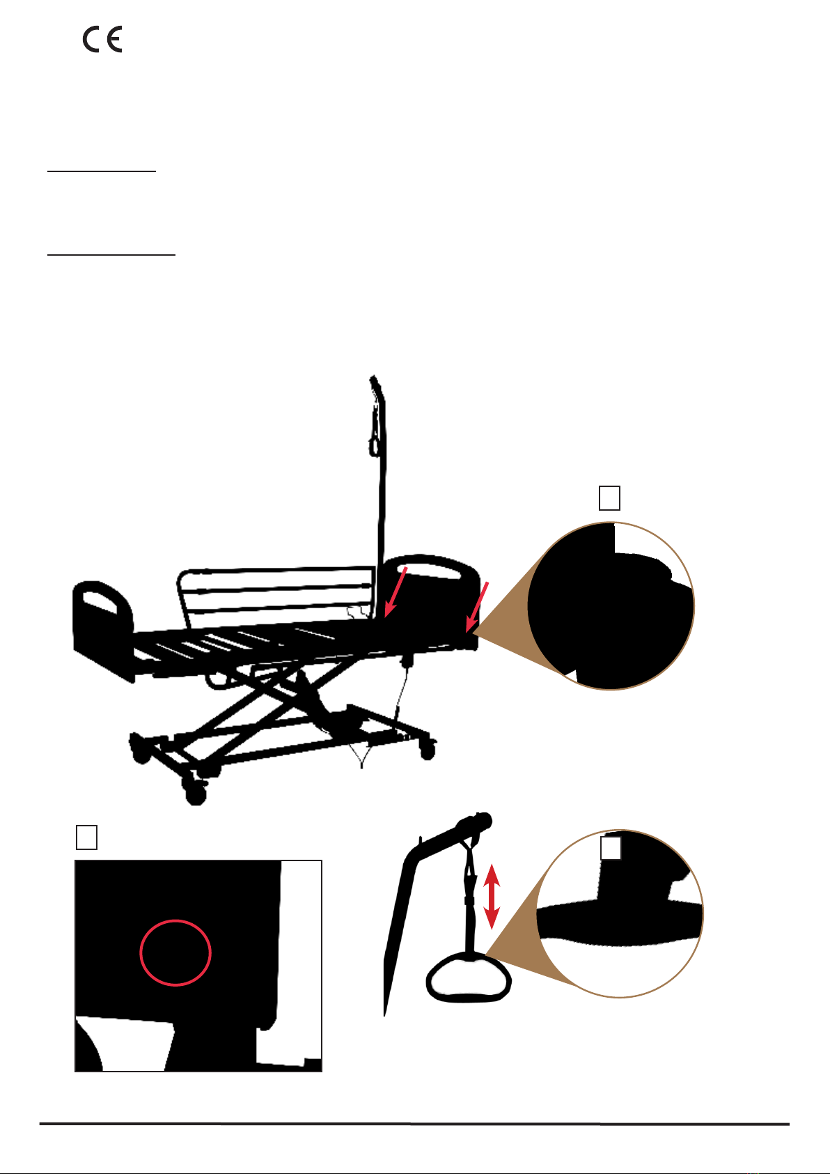
*Hang the remote control on the siderail or on the trapeze pole to avoid it from falling down. Make sure that the wire is correctly
positionned to avoid squeezing or crushing the cables. Lock the remote if necessary by removing the key on it.
*In case of doubt, if the bed appears to be damaged or if you suspect a malfunction, immediately unplug it from wall outlet, mark it
as „DEFECTIVE“ and contact your supplier.
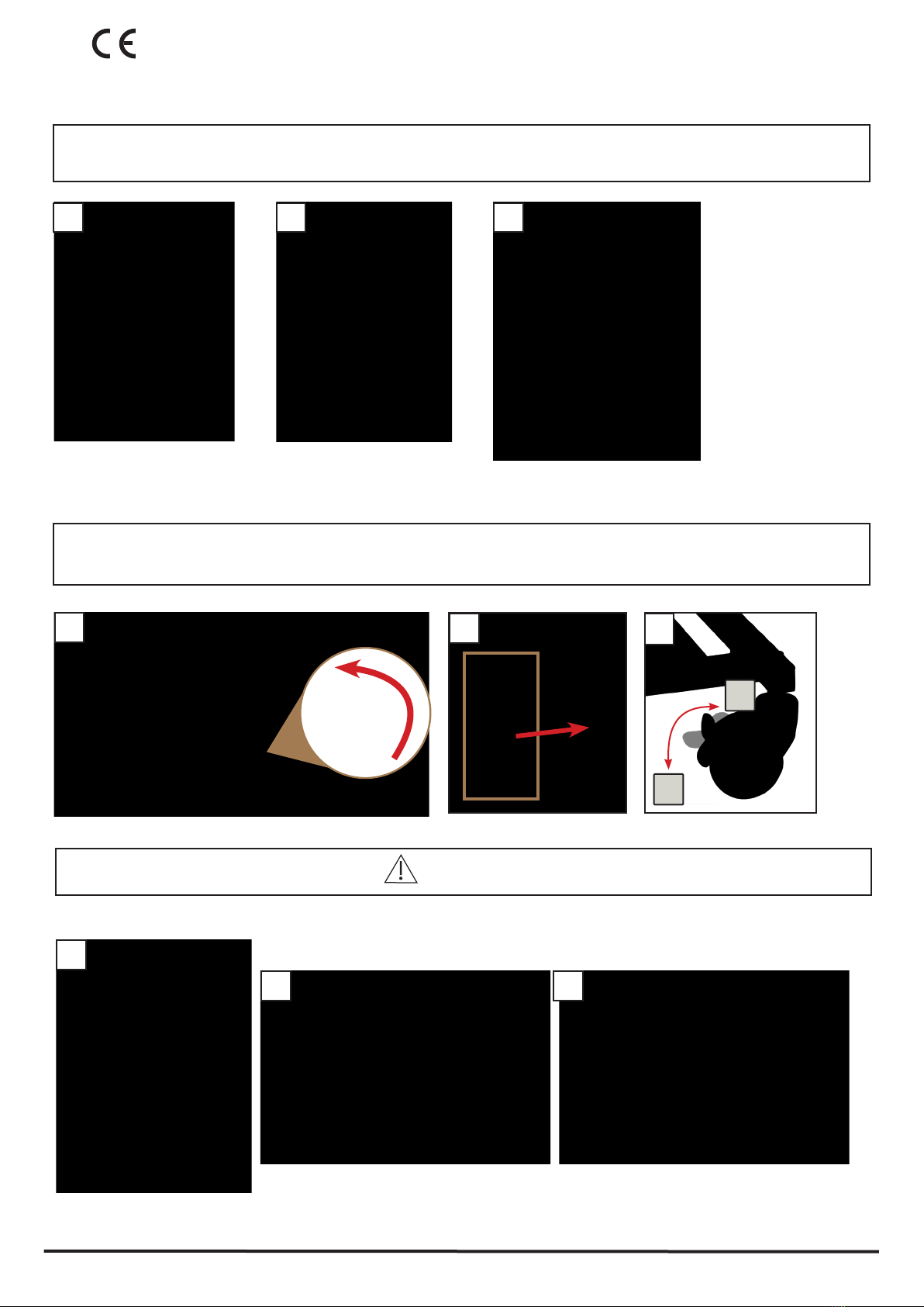
1.3 Product description
*The Home Care bed AMPLI + ® works as a convenient solution for taking care of inrm, disabled people in nursing homes or at
home.
*This bed can be used for care under the instructions of a physician and can serve in diagnosing, treatment and observation of a
patient. It is therefore equipped with a locking mechanism for the electrical adjustment functions.
*This bed has no special connector for a potential equalization.
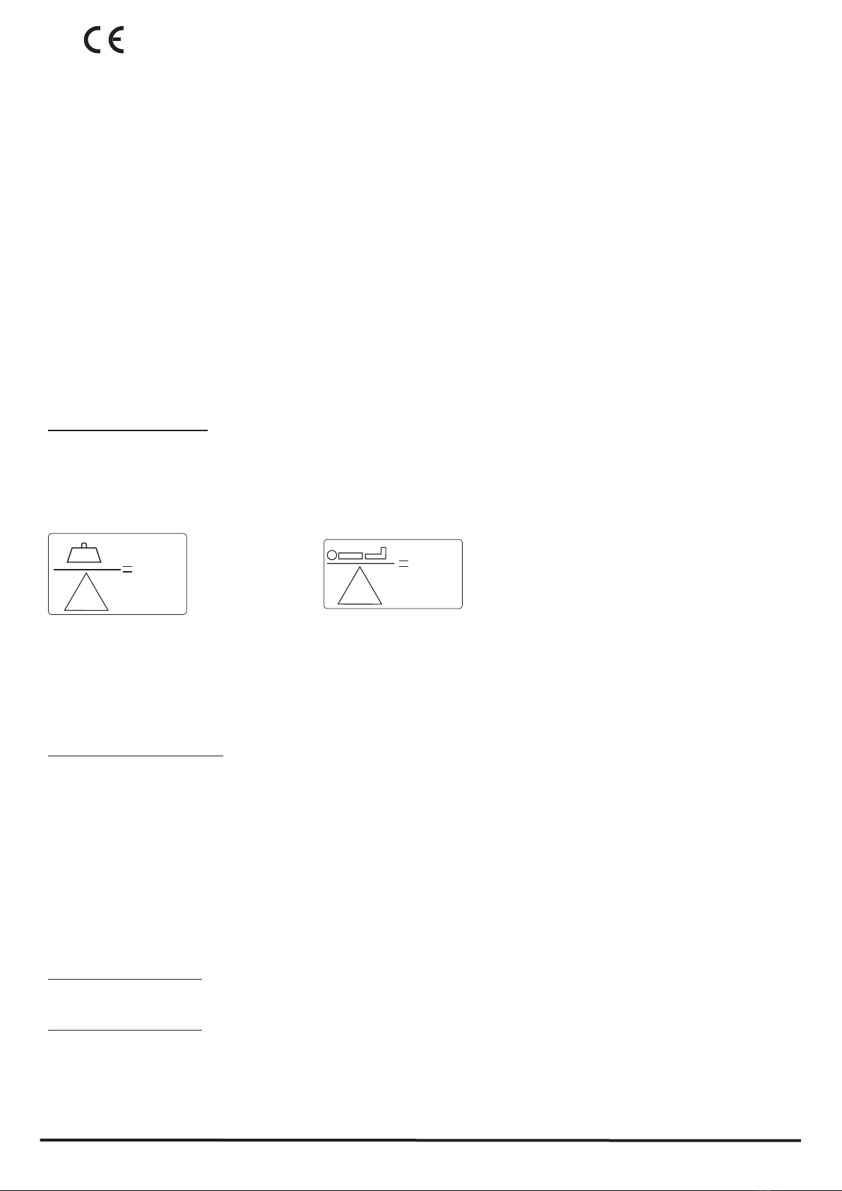
*Maximum permitted load on the bed 170 kg (weight of Patient + weight of accessories), maximum user‘s weight 135kg
!
135 kg
!
170 kg
*This bed shall not be used for patient under 146 cm and less than 40kg.
*This be shall only be operated by trained staff.
*This bed can be reused and rented.
*This bed can be moved accross the building, even with the patient lying on it.
*This bed must be used in a proper way as detailed in this instruction manual. Any other uses are strictly prohibited.
*This bed shall be used only per adults.
1.4 Technical information
The AMPLI + ® Home Care bed is delivered in parts, ready to be mounted. Siderails, Pole and bed ends are fastened on the bed
frame.
The bed is made of Epoxy steel and has 2 or 3 motors according to the version.
The bed can be mounted per ONE SINGLE qualied person. It consists in : one slats frame (in 2 parts), one scissor frame, 2 side rails,
1 lifting pole with trapeze, 2 bed ends. The bed has 2 holders for the lifting pole. It is equipped with 4 castors, 2 of them with brakes.
1.4.1 Slats bed frame
The Home Care bed exists in 2 versions :
-with 2 motors (4-sections mattress support) what means an electrical backrest, an electrical Hi-low adjustment, and a manual
legrest.
- with 3 motors (4-sections mattress supports) what means electrical backrest, Hi-low and legrest. Note that the legrest can be also
adjusted manually to reach the desired position.
4-section mattress support : a movable backrest, a xed middle section, a movable upper leg support and a movable lower leg support.
The frame is made of welded steel covered with a PE powder coating. All mobile parts, as well as the height of the lying surface can
be adjusted by means of 24V remote control. Note that the upper leg support can be adjusted manually to get the desired position.
3-section mattress support : a movable backrest, a xed middle section, a movable upper leg support and a movable lower leg support.
The frame is made of welded steel covered with a PE powder coating. All mobile parts, as well as the height of the lying surface can
be adjusted by means of 24V remote control excepts the legrest, that must be adjusted manually.
1.4.2 Side rails
The bed has 2 side rails which can be raised as a barrier or lowered when not needed. The side rails prevent the patient from
accidentally falling out of the bed.
5
21/03/2019 Rev.2 (04/12/2019)
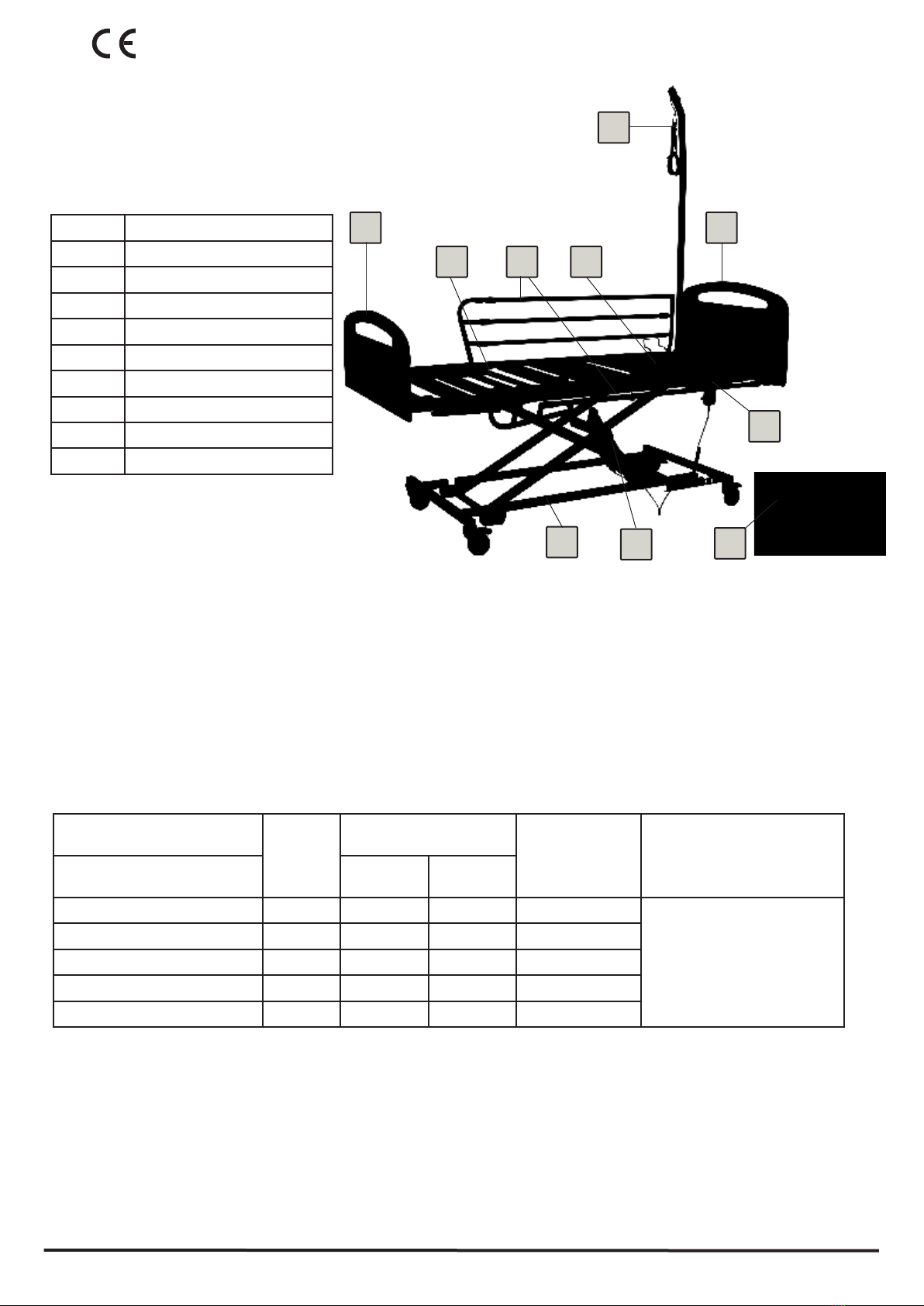
Mark Designations
1 base & scissor mechansim
2 legrest
3 backrest
4 side rails
5 liing pole
6 remote control
7actuator
8 bed ends
9 transport tray
1.4.3 Electrical adjustment system
The electrical adjustment system of this bed is error protected, ame-retardant (V0) and consists of:
*the central control box. For the safety of patient and user, the input voltage of 230V at 50-60Hz is converted to low voltage of 24V
by means of a transformer.
*a remote control with a sturdy hook to hang it.The remote control can be locked if necessary.
*one actuator to adjust the backrest.
*one actuator (only on full electrical models) to adjust the legrest.
* one actuator for the hi-low adjustment.
Description
Type
Timotion
Protection
IP = indice de protection Tensions
Power supply unit
Tension: 100-240Vac 50-60Hz Standard Washable
Actuator Hi-low TC21 IP54 IP66 70VA – 24Vcc
CAUTION:
Please follow the terms
of use indicated on the
labels on the bed.
Actuator backrest TA23 IP54 IP66 24 Vcc
Actuator Legrest TA31 IP54 IP66 24 Vcc
Remote control TA31 IP54 IP66 24 Vcc
Télécommande TH2 IP54 IP66 24 Vcc
1.4.4 Description of materials used
The Home Care bed is mostly made of welded steel covered with a PE powder coating. All surfaces are biocompatible.
Apart from the actuators, the bed consists of the following main materials:
1) Steel epoxy paint, zinc or chrome.
2) Plastic parts.
3) Melamine boards, medium (MDF) stained, varnished or coated with microber or leather depending on the model.
1.4.5 Noise level during motor adjustment: max. 53dB (A)
AMPLI + ® and its accessories
7
88
5
4
6
3
9
1
2

6
21/03/2019 Rev.2 (04/12/2019)
1.4.6 Storage
The bed and its components
must be stored as described
here:
Te mpé rat u r e Relative humidity without condensation
mini maxi mini mini
Storage 5° C + 50° C 20% 70%
Use 10° C + 40° C 20% 80%
Air pressure min. 700hPa max. 1060hPa.
1.4.7 Maximal load capacity and adjustments
Maximal Safe work load : 170kg
Maximal weight of the patient : 135kg
Maximal load on the lifting pole : 75 kg
Maximum load on the IV pole : 8kg
Backrest adjustment A: from 0° to around 67°
Legrest adjustment : from 0° to around 35°
1.4.8 Masses
* Bed with 3 actuators and without bed ends : 70kg
* Bed with 2 actuators and without bed ends : 68.2kg
* Scissor frame: 31.90kg included base: 12kg and scissor mechanism: 19kg
* Legrest with actuator and knee break: 19kg without knee break: 18kg
* Backrest : 19.60kg
1.4.9 Dimensions
* Bed slats frame : 2000*900mm
* Complete bed with siderails: 2050*1020mm
* Minimum Height : 200mm, Max. Height : 820mm.
* With central locking, Minimum Height : 230mm, Max. Height : 850mm.
* Height adjusts from 230 to 850mm
1.4.10 Standards
The bed complies with the following standards :
- Medical Products directive 93/42/EWG
- Medical electrical equipment -Particular requirements for medical beds IEC 60601-2-52:2009
- Medical electrical device-Part 2-52 : specic
- Biocompatibity according to EN ISO 10993-1*
- Risk Management according to ISO 14971
- Electro Magnetic Compatibility according to EN 60601-1-2*
- EN 60601-1 Medical electrical equipment. General requirements for basic safety and essential performance. Collateral standard.
Usability
AC
BD
E
E=180°-220°
D=0-9°
B=0-13°
C=180-92°
A=0-76°
7
21/03/2019 Rev.2 (04/12/2019)
2.Assembly and disassembly
2.1 General
The AMPLI + ® Home Care bed is delivered in parts, ready to be mounted. Siderails, Pole and bed ends are fastened on the bed frame.
The bed has 2 or 3 motors.
The bed can be mounted per ONE SINGLE qualied person. It consists in : one slats frame (in 2 parts), one scissor frame, 2 side
rails, 1 lifting pole with trapeze, 2 bed ends. The bed has 2 holders for the lifting pole and 1 for the infusion pole. It is equipped with
4 castors, with brakes.
You don‘t need any tools to mount the Home Care bed.
2.2 Bed delivered on the transport tray: Assembly steps
Before assembling the bed, look at it carrefuly to check that it is complete and has no visible damage.
Step 1 : Unpacking
The bed is delivered with its components in a box.
Step 2 : Removing the side rails and lifting pole
Open the box and remove the lifting pole and the two siderails (cut the RILSAN collar)
Roll the bed out of its box
Step 3 : Connecting the bed
Beware: make sure before connecting the bed, that all types of wires and cables (remote control cable, external electrical devices such
as compressors, lamps) are correctly positionned and don‘t risk to be crushed, sheared or torn apart when using the moving parts of
the Ampli Plus bed !
1-Unroll the cable and connect the bed to the main power supply
2-Lift the bed in the desired position using the remote control (3)
1 2 3
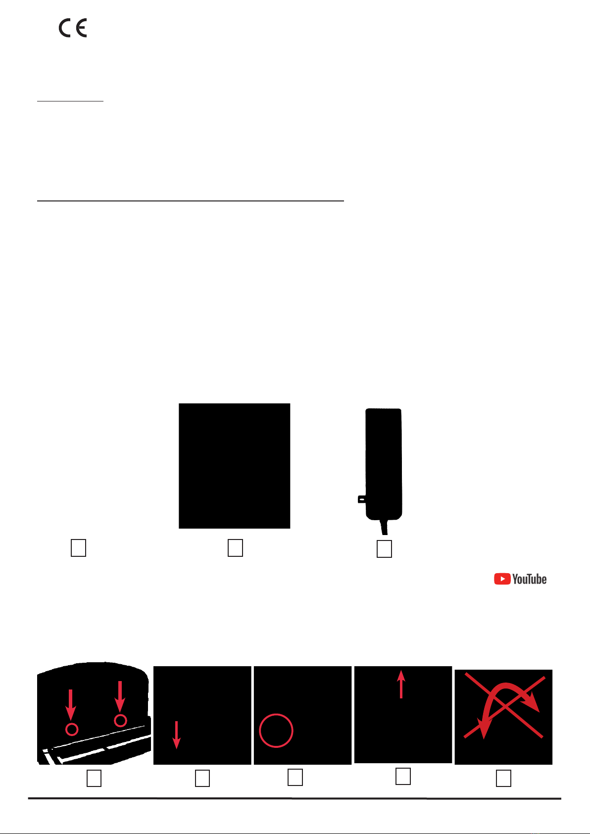
Step 4 : Mounting the bed ends (The highest board is the head panel.)
1-Insert the bed ends into the 2 holders located on the frame (in red on the photo) (1).
2-Push the bed ends downwards until they lock in the holders (2).
3-Make sure that the push button is fully engaged through the holder's hole. Check the stability of the bed ends
before use (3).
To remove the bed ends, depress the push button and lift up the bed end (4).
Beware: never screw or unscrew the bolts, you wouldn't be able to install/remove the bed ends (5).
1 2 3 4 5
* Norme collatérale. Aptitude à
l'utilisation.

8
21/03/2019 Rev.2 (04/12/2019)
21 2 3
4 4
2-Dismounting the side rails :
When the side rails are in upper position (in use), push on the pushbutton located on the backrest holder and pull out halfway the
quick release axel, proceed in the same way for the other end of the side rail, see photos (1), (2) and (3).
Then, holding the round part (A) with your right hand, left hand locadet on the upper pipe of the side rail, remove completely the
quick release axel from its holder, see photo (4). This is to avoid squeezing your left hand ngers.
For safety reasons, the side rails always
fold into the leg direction.
Make sure, before using the side rail
(folding or unfolding) that there are
no risk of crushing or squeezing the
patient‘s limbs. Thus, you will avoid
severe injuries.
1 2
Step 5 : Mounting the side rails
1-Mounting :
The bed is equipped with 4 side rails holders, 2 on both sides of the bed frame (1).
In order to mount easily the side rails, they are equipped with different locking pins: a red locking pin (for the left side rail
when sitting in the bed) and a black one for the right side rail. Their locations on the bed are also marked by a colour sticker,
see photo (1).
Our side rails are equipped with quick release axels which make them very easy to mount. Beware to place the rounded part (A) of
the side rails in the holder located on the legrest side. See photo 3.
Insert halfway the quick release axel into one of the holder by pushing on the pushbutton, see photo (2). Then do the same with the
other end of the side rail, see photo (3). When both axels are in position, push them completely into the holders until they are locked
in position.
Once mounted, it should be impossible to remove the side rails from their holders.
To use the side rails : lift up the side rail until the locking pin reaches its locking position. Check the correct xation of the side rails
before using, see photo (5). To fold the side rails : pull out the locking pin with one hand and fold in legrest direction with the other
hand, see photo (5).
4
4
A
5
3

9
21/03/2019 Rev.2 (04/12/2019)
Special safety notes for use of side rails:
* Use only parts in perfect condition, do not use bent, cracked or damaged side rails.
* Use only original HERDEGEN parts. Side rails from other suppliers won‘t t correctly on the Home Care bed.
* Before using the side rails evaluate and take in account the physical condition of the patient :
• If the patient is very nervous, restless or confused don‘t use the siderails but other means such as safety belts for
example.
• For very small patients, additional protective measures maybe necessary to reduce the distance between the tubes of
the siderail.
* Use mattresses adapted to the Home Care bed with a maximal height of 14 cm. Mattresses should be re resistant according
to DIN 597 Part 1 and 2 .
* Should specic antidecubitus mattresses be used, make sure that the side rail has an effective height of 22cm. If not, you must
nd solutions in order to ensure the safety of the patient.
* Check regularly the various elements of the siderails (holders, pins, tubes..). In case of damages, immediately remove the
side rail and use a new one.
* Check every week the correct xation of the side rails, screw again the knurled screws if necessary.
* Make sure, before using the side rail (folding or unfolding) that there are no risk of crushing or squeezing the patient‘s limbs.
Thus, you will avoid severe injuries.
If the upper rules are not followed, there are risks of severe injuries for the patient such as
crush , pinch point injuries and fall risks.
Beware: in case of use of incompatible mattresses, there are risks of severe injuries for the patient !
MATTRESS
Please respect the medical prescription or recommendations regarding the size of the mattress.
Check the user manual if necessary.
Width of the bed's frame: 90cm
Suitable mattresses for the Ampli Plus medical bed:
Width: 86cm minimum - 90cm maximum
Length: 196cm
High resiliency foam of 34Kg/m³ minimum
3-Using the side rails :
To unlock the side raol :
1- place your hands as described : right hand on the round part (A) of the side rail, see photo (1) , left hand on the upper tube (B) of
the side rail, see photo 1.
Unlock the side rail by pulling out the locking pin, see photo 2.
Fold the side rail, see photo 3
1
A
B
2 3
10
21/03/2019 Rev.2 (04/12/2019)
The lifting pole enables the patient to get out of the bed easily.
Beware: The maximum load capacity of the pole is 75kg at the front end.
Mounting the pole
In both corners of the backrest are two pole holders (1) with a notch which restricts the swivel range (2).
The pole has a metal pin which restricts the swivel range (3+4).
Insert the pole in the pole holder and check that the metal pin is in the notch of the pole holder.
Mounting the trapeze
The trapeze pole should be installed on the side where the patient gets in and out of bed. The pole can be moved on the left or right
sides. Don‘t swivel the pole outside of the bed.
The trapeze (5) needs to be attached to the pole for use.
Pull the loop over the top of the pole (5) and adjust the height of the trapeze using the strap (from 55 cm to 70 cm) (6).
Make sure that the strap is positionned correctly through the buckle and tightly pull the trapeze downward to check it is secured.The
trapeze has a date clock (7). With normal use the trapeze will last for ve years. After 5 years, replace the trapeze.
Step 6 : Mounting and using the lifting pole.
1
2 3
11
21/03/2019 Rev.2 (04/12/2019)
Step 7 : Mounting and using wooden side rails
Wooden side rails are delivered with : 2 sets, each of them including 2 articulated plastic pins (drawing A) et 2 preholed wooden
beams (photo B). Bed ends are equipped with guide tracks on each sides in which the plastic pins will be pulled up (drawing C).
To mount the wooden side rails, please follow below steps :
1- Adjust the bed to its highest position
2- Insert the plastic pins into the bed end's guide tracks, rounded side must point upwards (photo 1, component A) pushing on the
locking pushbutton , see photo (2), in order to enable the part to go through.
3- Now plug one side rail beam onto the pair of plastic pins, leting the other end of the side rail beam rest on the oor, see photo 3.
4- Insert second part "A" into the other end of the wooden beam.
5- Insert the second end into the bed end, as done in 2, see photos 4 and 5.
6- Push on the locking pushbutton "D" to adjust the wooden side rails, see photo 6.
Make sure, before using the side rail (folding or unfolding)
that there are no risk of crushing or squeezing the patient‘s
limbs. Thus, you will avoid severe injuries.
Articulated plastic pins Wooden side
beam, frontview
A B
A1
Special safety instructions for use of
side rails : see page 9.
2
1
A
3
B
B
4
5 6 D
C
Guide tracks
Locking pushbutton

12
21/03/2019 Rev.2 (04/12/2019)
Step 8: Connecting the backrest and the legrest (on 3-motors beds only)
Unroll the electrical cable, connect the actuator to the main power supply and lift the bed to its maximum height.
Remove the cover of the power control box with a screwdriver or a standard key car for example.
Plug the actuators respecting the colours: blue in blue and orange in orange.
Insert the cables in their cable clamps and place back the power box cover.
On 3-motors bed, you need to connect the actuator for the legrest, on 2-motors bed, only the backrest actuator.
Step 9 : Remote control
The Home Care bed is delivered with a precabled remote control.The electrical adjustments of the hi-low,
backrest and legrest (only for 3 motors version) can be done using the remote control.
• The remote control is equipped with a plastic hook to hang it.
• The spiral cable enables easy movement.
• The remote control is waterproof and washable.
• The remote control is equipped with a safety key to lock it
As long as you press the remote control button, the corresponding actuator will work. Adjustments are
possible in both directions, up or down.
The functions of the buttons are :
• *UP
• *DOWN
For safety reasons, there is a locking system built in the remote control
Special safety notes for use of side rails:
* Use only parts in perfect condition, do not use bent, cracked or damaged side rails.
* Use only original HERDEGEN SAS parts. Side rails from other suppliers won‘t t correctly on the Home Care bed.
* Before using the side rails evaluate and take in account the physical condition of the patient :
• If the patient is very nervous, restless or confused don‘t use the siderails but other means such as safety belts for example.
• For very small patients, additional protective measures maybe necessary to reduce the distance between the tubes of the
siderail.
* Use mattresses adapted to the Home Care bed with a maximal height of 14 cm. Mattresses should be re resistant according to DIN
597 Part 1 and 2 .
* Should specic antidecubitus mattresses be used, make sure that the side rail has an effective height of 22cm. If not, you must nd
solutions in order to ensure the safety of the patient.
* Check regularly the various elements of the siderails (holders, pins, tubes..). In case of damages, immediately remove the side rail
and use a new one.
* Check every week the correct xation of the side rails, screw again the knurled screws if necessary.
* Make sure, before using the side rail (folding or unfolding) that there are no risk of crushing or squeezing the patient‘s limbs. Thus,
you will avoid severe injuries.
If the upper rules are not followed, there are risks of severe injuries for the patient such as
crush , pinch point injuries and fall risks.
Beware: in case of use of incompatible mattresses, there are risks of severe injuries for the patient !
MATTRESS: Please respect the medical prescription or recommendations regarding the size of the mattress. Check the user manual
if necessary.
Width of the bed's frame: 90cm
Suitable mattresses for the Ampli Plus medical bed: Width: 86cm minimum - 90cm maximum Length: 196cm
High resiliency foam of 34Kg/m³ minimum
backrest
legrest
hi-low
Remote control Clip to maintain cables
Cover
Backrest adjustment
Legrest adjustment
Hi-Low of the bed
Key of the TH2 remote control
(locking and unlocking):
Key inserted: remote control unlocked
Key removed: remote control locked
TH2
remote control
Power control box Cables connection
13
21/03/2019 Rev.2 (04/12/2019)
Step 10 : Mattress holders
Step 11 : Emergency lowering of the backrest.
In case of power failure, the backrest can be lowered manually.
This function MUST be operated by at least two persons as the backrest may collapse and causes severe
injuries. It MUST be done only per trained staff paying attention to the risks.
We advise you strongly to operate this function under normal conditions to get experienced.
Relieve the load on the backrest :
• the rst person holds the backrest in an upper position.
• the second person removes the lynch pin of the actuator.
• the actuator is detached from the backrest and falls down (it is still xed to the scissor frame).
• the rst person brings down the backrest.
1
2
Special safety instruction for the use of actuators and electrical parts
*Before using the actuators, make sure that no limbs from patient or third-person can be crushed or squeezed by the mobile parts
of the bed.
*For safety of the patient, lock the remote control when the side rails are in function.There are high risks of crushing or squee-
zing the patient‘s limbs.
*When adding accessories on the bed, ensure that those don‘t create the risk for the patient to be hurt or crushed. If this is the
case, disconnect the remote control or remove the accessory.
*In that case, place the remote control out of the patient‘s reach.
*Ensure that cables and wires of the remote control and central control box can‘t be damaged in other ways.
*Make sure when moving the bed around that wires and cables can‘t be damaged or rolled over.
*Unplug the power cord from the wall outlet, before moving the bed around.
*Ensure that there is enough space available to use the moving elements of the bed in a proper way. No furniture, window
frames should be in the way.
*An electronic overload detector switches off the central control box, when the load is too great. After clearing the overload and
pressing the remote control again the central control box will work again.
*After some time the remote control will work again if you press on the adjustments button.
*The maximum period of operation shall not exceed 2 minutes. Afterwards you must respect a pause of 18 minutes. It is also
possible to operate 1 minute followed by a 9 minutes pause.
* If the maximum continuous run time is not respected, a thermal safety component switches off the power for safety reasons.
The remote control will stop working for a more or less longer time, depending on how big the overload was.
*Please respect the adjustment possibilities given in &1.4.7.
* If you use in the same time, various electronic equipment, particularly if those are close to the bed, electronic disturbances
(similar to the interfering noise heard on the radio ) could occure. In such rare cases, increase the distance between the devices,
do not use the same wall outlet, or temporarily switch off either the interfering device or the one being interfered with.
* Electrical connections :
• The central control box supplies power to the actuators.
• Actuators must be correctly pluged into the central control box. The plugs at the end of each cable is equipped with a colour
sticker to avoid wrong plug in.
• Ensure that cables are in a perfect condition and don‘t risk being damaged or crushed when using the bed.
• Cables are equipped with strain reliefs [4] and cable holders are located under the bed frame. Please hang the cables there.
14
21/03/2019 Rev.2 (04/12/2019)
1 2
Step 13 : Central locking
Available only on some models.
2 3
1
Step 12 : Castors
The bed stands on 4 castors with brakes
To brake : push the footlever down [1].
To drive: push the footlever forward [2].
Make sure that the bedframe is in the lowest position and remote
control is correctly positionned, before moving the bed around.
How to use the central locking :
- Lower position (1): 4 castors are braked.
- Medium position (2): 4 castors are released.
- Upper position (3): one steering wheel and 3 released castors for an easier rolling away of the bed.

15
21/03/2019 Rev.2 (04/12/2019)
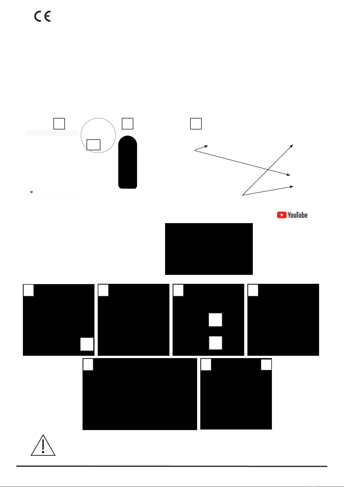
2.3.Mounting the bed when it is delivered on its trolley
Many movies are available to teach you the various mounting possibilities
General information Installation with the trolley Placing the bed
on the Transkit
Method 1 Method 2
Mounting from the Transkit
Method 1 Method 2

16
21/03/2019 Rev.2 (04/12/2019)
Locking the castors:
for safety lock the castors of the
transport tray by pushing the
footlever down.
Removing the pole:
remove the liing pole from its holder without scratching
the bed.
Before assembling the bed, look at it carrefuly to check that it is complete and has no visible damage. Please contact us if any
damges is noticed.
Step 1 : Unpacking and lifting pole removal
Extract the side rails by pushing
on the quick release axles, see
photos A et B.
Step 2 : Side rails
B
A

17
21/03/2019 Rev.2 (04/12/2019)
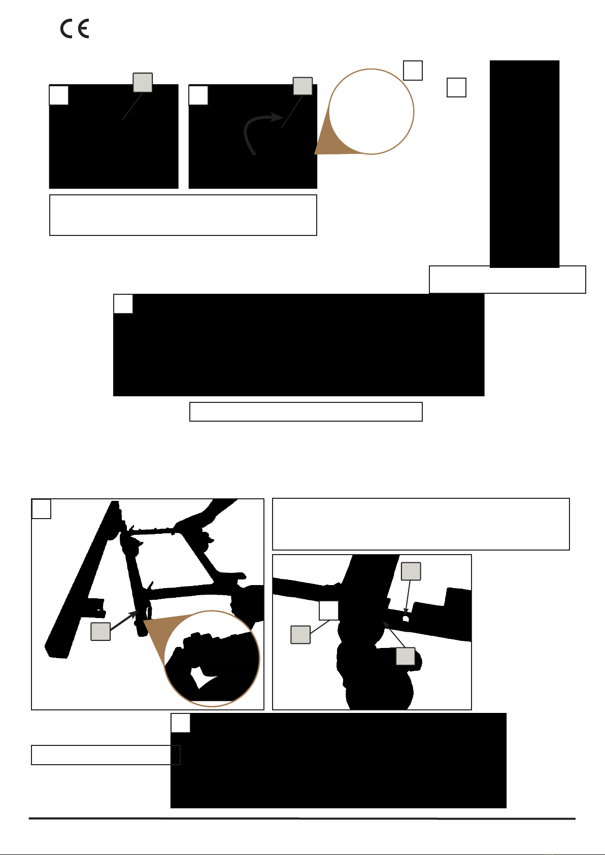
Slightly tilt the legrest toward your body, to make the removal of bed ends easier.
Unclip the bed ends by pulling them carrefully up. Proceed carefully in order not to scratch the panels.
Follow below steps 1 to 4
Step 3 : removing the bed ends
1-Unlock the legrest (1) by rotating the wing bolts (1) which are maintaining it on the bed ends holders.and move it slightly back-
ward to enable an easier removing of the bed ends. See photos A et B
BA
1
1 1
1
1 3 4
2
18
21/03/2019 Rev.2 (04/12/2019)
Step 4: Removing the legrest
Once the bed ends are removed from the trolley, remove the legrest from the transport tray, and place it apart. The legrest stands
up on its own, see photos A, B, C.
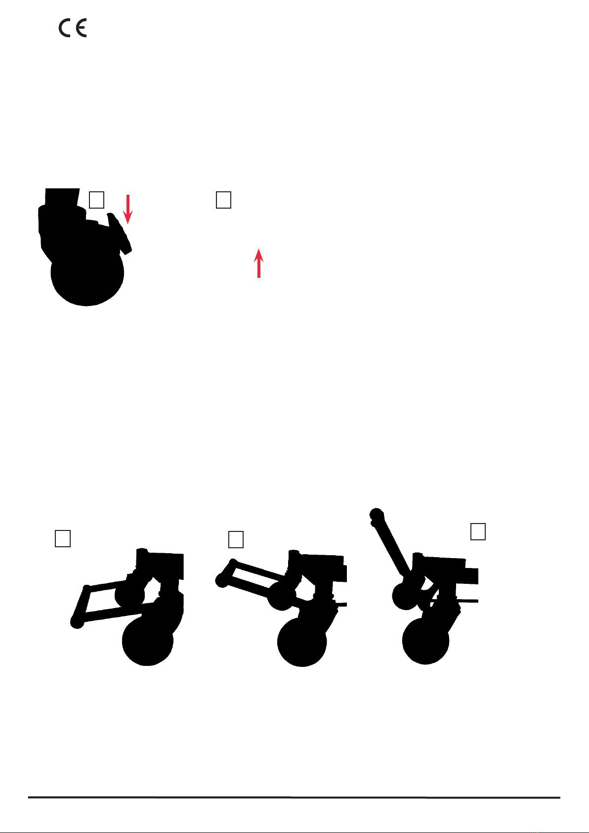
Step 5: Removing the base
Loosen the knurled screw which holds the base on the trolley by rotating the knurled screws rmly anticlockwise, see photo A.
Screw the knurled screw pn the base frame, see photo B
Lock the 4 castors, see photo C : to lock see (1) to unlock see (2).
A
Bring delicately the base on the oor, see photos C. Hold it rmly. High risk of injury if the bed falls down.
B C
C
C C
1
2
C
AB
19
21/03/2019 Rev.2 (04/12/2019)
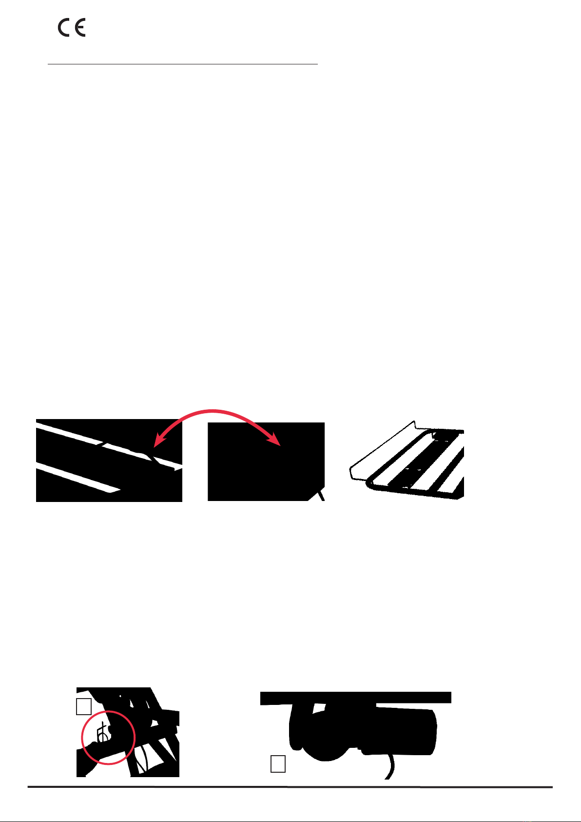
Step 6 : Removing the backrest from the trolley
Step 7 : Removing the trolley from the basis.
Unlock the backrest by rotating the wing bolts (1) which are
maintaining it on the trolley by rotating them clockwise, see
photos A et B. Align both arrows, see photo B'.
Press on the pushbutton (1), see photo A, and rotate the trolley to extract it from the guide tracks.
Remove the trolley out of range not to be disturbed while mounting the bed.
To mount the trolley, emboiter le côté droit puis le côté équipé du bouton poussoir.
1
2
3
B
A
1
1
1
Place the backrest on the oor, it
stands up on its own, see photo C.
After that, remain the basis and the trolley, see photo D.
A B
D
C
Base without trolley, see photo C
C
Special use of the trolley, see photo B
The holes (1+2) makes the transport tray works as a bed/wall protector.
The third hole (3) enables the transport tray to be completely removed
under the bed.
B'

20
21/03/2019 Rev.2 (04/12/2019)
Step 8 : Connecting the backrest
1-Unroll the electrical cable, connect the actuator to the main power supply, see photos A, B and C.
2-Using the remote control, adjusts the height of the bed until your reach the black sticker (1) located on the base, see photo D.
A B C
1
D
D
Table of contents
Other Herdegen Medical Equipment manuals


