HERKULES G100 User manual
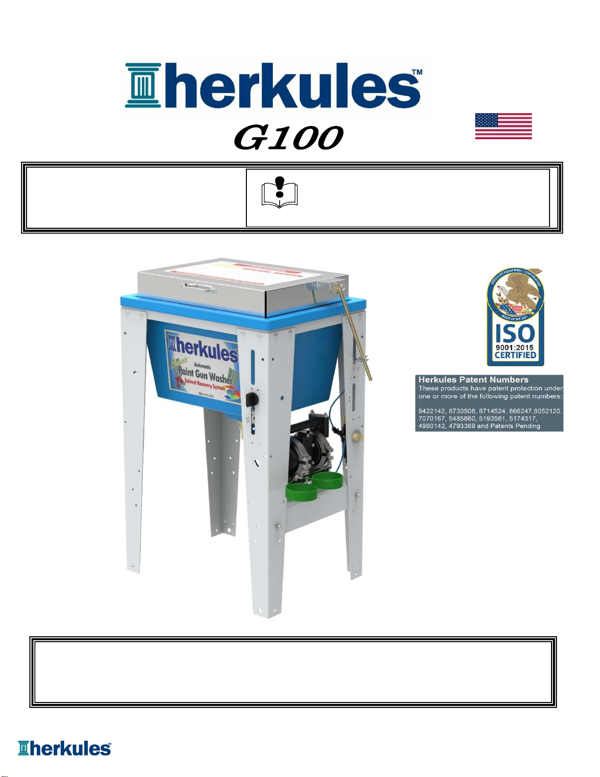
Part# 1002423-12
8/24/2020
.This manual contains important information concerning the
installation and operation of the gun washer listed above.
Read manual thoroughly and keep for future reference.
INSTRUCTIONS
OWNERS MANUAL
Made in USA
Toll Free: 800-444-4351
Phone: 248-960-7100
Fax: 248 960-7109
Website: www.herkules.us
E-mail: info@herkules.us Herkules Equipment Corporation
2760 Ridgeway Court
Walled Lake, MI 48390-1662 USA
Page 1 of 20 Call: 1-800-444-4351

Warranty ……………………………………………………………………………………………………………….................... 3
Model Information ……………………………………………………………………………………………………………. 4
Warnings ……………………………………………………………………………………………………………………… 5-6
Assembly Instructions ……………………………………………………………………………………………………….. 7-9
Installation ………………………………………………………………………………………………………………….. 10
Operation ……………………………………………………………………………………………………………………. 10-11
Preventive Maintenance ………………………………………………………………………………………………………. 12
Troubleshooting ……………………………………………………………………………………………………………… 13
Drawings with Part Lists …………………………………………………………………………………………………… 14-20
Schematic ………………………………………………………………………………………………………................... 21
Herkules Equipment Corporation
A U.S.-based manufacturer, Herkules Equipment Corporation offers a diverse line of products that support multiple
industries by improving efficiency, productivity, ergonomics, comfort, and safety in the work environment. The
company consists of the three product lines: Herkules, Enkon and BossLifts.
Since 1985, Herkules has designed, engineered and manufactured quality products at our Walled Lake,
Michigan facility. Our company supports our products after delivery, with U.S. based customer service, and
replacement parts, enabling our customers to proceed with confidence.
To learn more about Herkules, visit http://herkules.us. Contact us at info@herkules.us with any
questions or concerns.
Thank you for purchasing a Herkules product!
Table of Contents
Page 2 of 20 Call: 1-800-444-4351
Warranty
At Herkules we take great pride in the construction of our American-made products, and we stand behind their reliability.
Our limited liability warranty coverage for Paint Gun Washers warranties the unit for a period of 12 months. Washer pumps
have a separate warranty; the Herkules 338 pump is protected for a period of 2 years from the date of purchase. All other
pumps, including rinse pumps, are warrantied for 12 months.
This warranty does not apply to equipment damaged from accident, abuse, overload, misuse, negligence, improper
installation, abrasive or corrosive materials, or shipping damage.
In the event of product failure, the defective item must be returned, freight prepaid, to the Herkules manufacturing plant for
repair or replacement. If repairs are required, Herkules will not be liable for these repairs to take place in the field regardless
of the application. Proof of purchase and date of purchase must be confirmed. An RGA* (Returned Goods Authorization) and
written approval from Herkules must be obtained before any goods can be shipped to Herkules. We reserve the right to
Determine whether failure is due to defective material, normal wear, and / or other causes.
There are no warranties which extend beyond the description on the face hereof. Herkules
disclaims any warranty of merchantability or fitness for a particular purpose in connection with
the Buyer's purchase of any Product under this agreement. Damages are limited to the sales
price of the Herkules system. The terms and conditions herein represent the entire agreement
between Herkules and the Buyer. Any prior / future representations do not apply.
*To obtain a RGA, contact Herkules at 1-800-444-4351 and have the item model, serial numbers, and invoice number if applicable.
Upon receipt of your equipment, please write your purchase information below. Please retain this manual for your records.
Serial Number Model Number
Purchase Date Distributor (if applicable)
IMPORTANT NOTICE: if you have a problem with your Herkules product,
DO NOT RETURN TO PLACE OF PURCHASE
Contact Herkules: by phone 1-800-444-4351: by email, info@herkules.us: or on the web at herkules.us/contact-us.
IMPORTANT NOTICE: if you have a problem with your Herkules product,
DO NOT RETURN TO PLACE OF PURCHASE
Contact Herkules: by phone 1-800-444-4351; by email, info@herkules.us; or on the web at herkules.us/contact-us.
Page 3 of 20 Call: 1-800-444-4351
Part #
Description
001-702
Bolt Hex 1/4-20 x 1/2 Z 2 ea.
001-705
Flat washer 1/4" 2 ea.
002-158
Screw #14 x 3/4 - zinc 2 ea.
002-161
Flat washer #10 5 ea.
008-244
Acorn nut 1/4-20 - nickel 2 ea.
1000252
Cotter pin 1 ea.
1000652
Clevis pin 1/4 dia. 1 ea.
1002423
Owner's Manual 1 ea.
11130
Slotted plug - yellow 1 ea.
11957
Actuator 1 ea.
53B
Stem support female 1 ea.
83
Hex bolt 1/4-20 x 1 - zinc 2 ea.
84
Hex nut 1/4-20 - zinc 2 ea.
85
Lock washer 1/4" 4 ea.
C9A
Nipple 1/8 NPT x 4-1/2 1 ea.
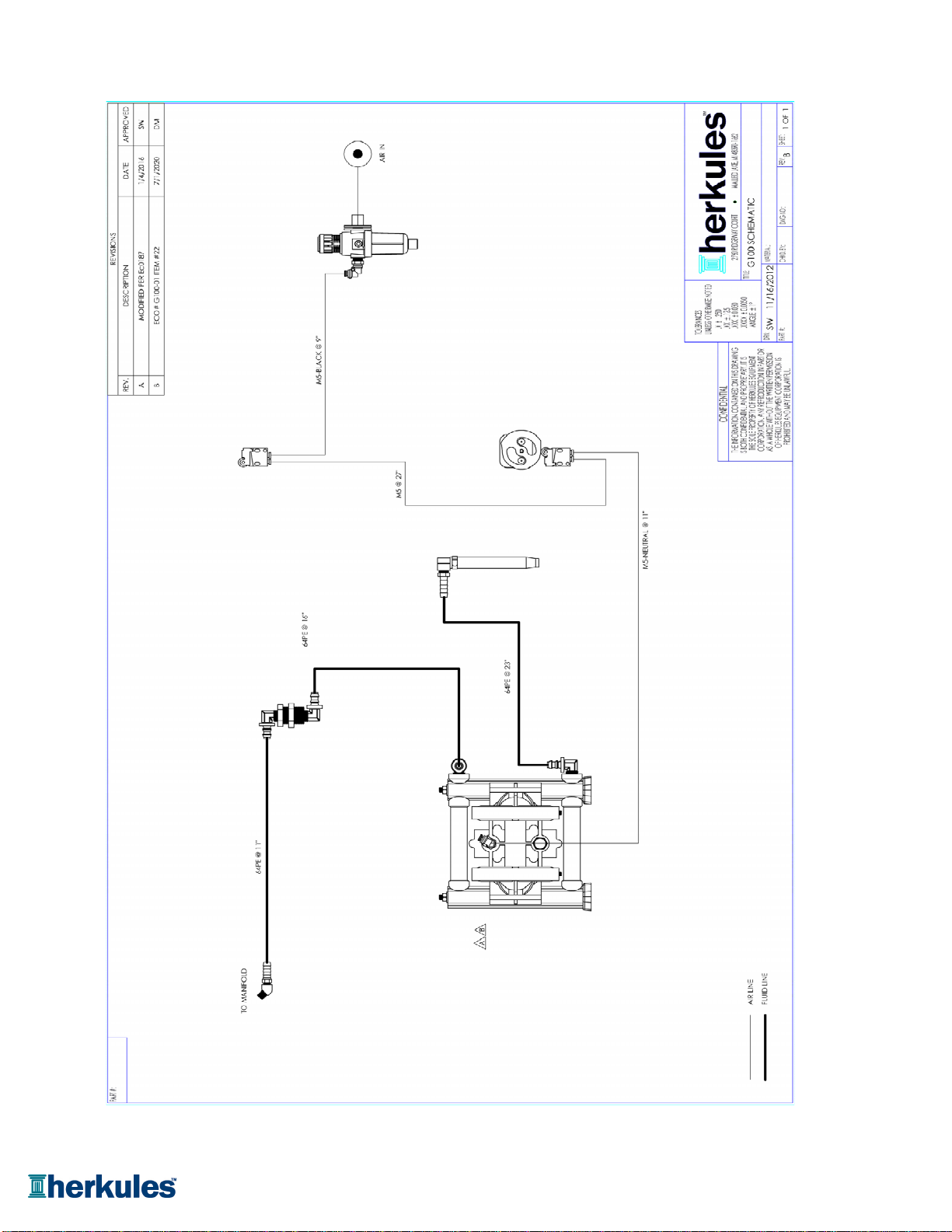
M5
Tube 5/32 blue 27 in.
M5-BLACK Tube 5/32 black
9 in.
M5-NEUTRAL Tube 5/32 clear
11 in.
M230-002
Knob for timer 1 ea.
M230-005
Spacer 1/2" Nylon 1 ea.
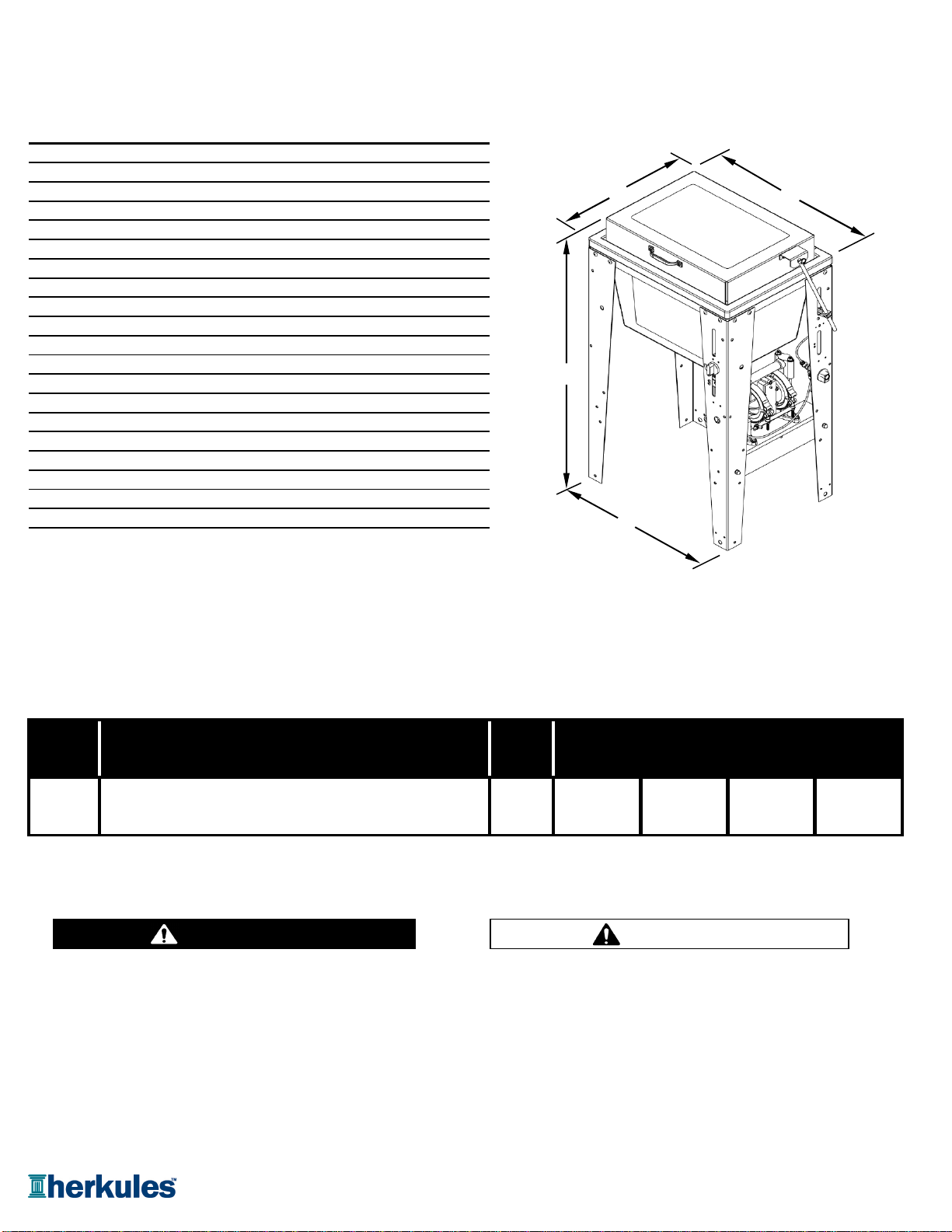
NOTE: Dimensions listed are overall measurements.
*Customer should review and verify all parts are present before starting assembly
A
B
C
D
One gun, one cup paint gun washer equipped 35.625 16.75 22.5 20.375
with diaphragm pump, filter-regulator and timer. (905) (425.5) (571.5) (517.5)
Cleans exclusively either solvent or water based paints.
G100 20.2
Model Information
Model Description Weight Dimensions (in/mm)
Warning Symbol Caution Symbol
(lbs/kg)
44.5
Quantity
A
BC
D
Parts bag contents
CAUTIONWARNING
This symbol alerts you to the possibility of serious
injury or death if you do not follow the instructions. This symbol alerts you to the possibility of damage to
or destruction of equipment if you do not follow the
instructions.
Page 4 of 20 Call: 1-800-444-4351
EQUIPMENT MISUSE HAZARD
Equipment misuse can cause the equipment to rupture, malfunction, or start unexpectedly
and result in serious injury.
•
This equipment is for professional use only.
•
Read all instruction manuals, tags, and labels before operating the equipment.
•
Use the equipment only for its intended use.
•
Do not alter or modify this equipment.
•
Do not exceed the maximum working pressure of the lowest rated system component.
•
Do not operate the gun washer at a pressure above the maximum working pressure rating of the
gun(s) being cleaned.
•
Route the hoses away from traffic areas, sharp edges, moving parts, and hot surfaces.
•
Do not use the hoses to pull the equipment.
•
Do not move pressurized equipment.
•
Use fluids or solvents that are compatible with the equipment wet parts. Read the fluid and
solvent manufacturer's warnings.
•
Comply with all applicable local, state and national fire, electrical and other safety regulation.
PRESSURIZED EQUIPMENT HAZARD
Spray from hose leaks, ruptured components, or from operating the gun washer with an open lid
can splash fluid in the eyes or on the skin and cause serious injury.
•
A safety device has been installed to shut off the pump when the gun washer lid is opened.
Do not tamper with, or alter, this device.
•
Open the gun washer lid slowly.
•
Do not prop the gun washer lid open with an object or by any other means.
•
Do not stop or deflect fluid leaks with your hand, body, glove, or rag.
•
Tighten all fluid connections before operating the equipment.
•
Replace worn, damaged, or loose parts immediately.
WARNING
WARNING
Page 5 of 20 Call: 1-800-444-4351
FIRE AND EXPLOSION HAZARD
Improper grounding, poor air ventilation, open flames, or sparks can cause a hazardous condition
and result in fire or explosion and serious injury.
•
Ground the equipment. See Installation section for grounding procedure.
•
Provide fresh air ventilation to avoid the build up of flammable fumes from the cleaning solution.
•
Extinguish all open flames or pilot lights in the gun washer area.
•
Disconnect all electrical equipment in the gun washer area.
•
Keep the gun washer area free of debris, including cleaning solutions, rags, and gasoline.
•
Do not turn on any light switch in the gun washer area while operating or if fumes are present.
•
Do not smoke in the gun washer area.
•
Do not operate a gasoline engine in the gun washer area.
•
Follow the gun manufacturer's solvent and other cleaning recommendations.
•
Use solvent with the highest possible flash point.
•
If there is any static sparking while using the equipment, stop operation immediately. Identify and
correct the problem.
•
Drain the cleaning solution into a proper storage container when gun washer(s) is not in use.
TOXIC FLUID HAZARD
Hazardous fluids or toxic fumes can cause serious injury or death if splashed in eyes or on the
skin, swallowed, or inhaled.
•
Know the specific hazards of the fluid you are using. Read the fluid manufacturer's warnings.
•
Store hazardous fluid in an approved container. Dispose of hazardous fluid according to all local, state
and national guidelines.
•
Wear the appropriate protective clothing, gloves, eyewear and respirator.
•
Pipe and dispose of the exhaust air safely. If diaphragm fails, the fluid may be exhausted along with
the air.
WARNING
WARNING
Page 6 of 20 Call: 1-800-444-4351
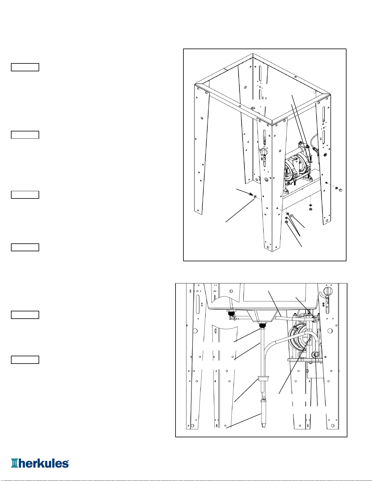
Stand and tub connections
Position the pump mount bracket between the timer
leg and the filter/regulator leg of the stand assembly.
Attach the pump mount bracket to the stand using (2)
1/4-20 x 1/2 hex bolts, (2) #10 flat washers, (2) 1/4"
lock washers and (2) 1/4" acorn nuts per leg [see fig.1].
Attach the pump to the stand using the (2) 1/4-20 x 1
hex bolts, (2) 1/4" flat washers, (2) 1/4" lock washers
and (2) 1/4" hex nuts per leg [see fig.1].
Fluid hose connections
STEP 3
Connect the drain hose assembly to the hose barb
(on the bottom of the tub) and tighten. This connection can
be easily disconnected when inserting into a 5-gallon can.
[see fig.2].
Ensure bulkhead DOES NOT TURN when tightening.
STEP 4
Attach the siphon filter to the 23" length of black hose by
inserting the barb into the end of the hose. Slide the
yellow slotted plug over the opposite end of the hose
so that the threads are in the direction of the filter
[see fig.2].
Attach the other end of the 23" hose to the lower (IN)
90° barb on the pump [see fig.2].
STEP 6
Run the 16" black hose from the upper (OUT) 90° barb
on the pump to the 90° barb at the rear-left corner
on the underside of the tub [see fig.2].
Assembly Instructions
STEP 5
STEP 1
STEP 2
16" Black Hose
23" Black Hose
Plug
Siphon Filter
Drain hose assembly
Hose barb
fig.2
Hex bolt
1/4-20 x 1
1/4" Flat Washer
fig.1
Hex bolt
1/4-20 x 1/2
Flat washer #10 1/4" Acorn nut
1/4" Hex nut
1/4" Lock Washer
(IN) barb
(OUT) barb
Page 7 of 20 Call: 1-800-444-4351
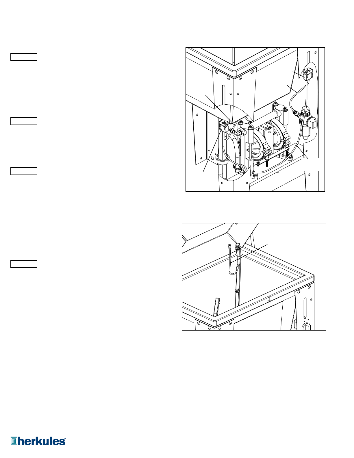
Air hose connections
Connect the black 5/32" air hose between the regulator
and the air-in port of the limit valve located on the rear leg
of the gun washer. Press tubing in through the collar until
seated. Pull firmly on hose to test for a tight connection.
[see fig.3].
Note: Air-in port of limit valve is the port opposite the roller.
Connect the blue 5/32" air hose between the air-in port of
limit valve (located on the front leg) and the air-out port of the
limit valve (located on the rear leg of the gun washer).
Press tubing in through the collar until seated. Pull firmly on
hose to test for a tight connection [see fig.3].
Connect the clear 5/32" air hose between the pump and
the air-out port of the limit valve (located on the front leg
of the gun washer). Press tubing in through the collar until
seated. Pull firmly on hose to test for a tight connection.
[see fig.3].
Grounding the lid
Verify grounding wire is attached to both the spray manifold
and the lid [see fig.4].
STEP 9
STEP 8
STEP 10
Assembly Instructions
STEP 7
fig.3
Limit
valve
Limit
valve
Black air
hose
Blue air
hose
Clear air
hose
fig.
4
Ground wire
front leg
Page 8 of 20 Call: 1-800-444-4351

Connecting lid rod and actuator linkage
STEP 11
Slide the actuator over the lid rod and hand tighten approx.
2" from the end of the rod. Insert the actuator into the large
slot in the right rear leg [see fig.6].
STEP 12
Attach the lid rod to the lid bracket using the 1/4" clevis pin
and circular cotter pin supplied [see fig.6].
STEP 13
To adjust the actuator, close the lid and loosen the set
screw on the actuator. Slide the actuator down until it
completely closes the limit valve and retighten the set
screw [see fig.6].
Note: It is necessary for the roller switch to be completely
engaged for the pump to operate properly. Be sure that
the actuator is absolutely secure and at the lowest possible
point.
If the pump is operating slowly, check the actuator first.
Final Assembly
Using a 3/8" hex socket with either a ratchet or power drill,
drive the (2) #14 screws through the two holes in the
frame and into the underside of the tub's lip [see fig.7].
Note: Be sure to provide pressure down from the top of
the tub while driving the screws. Do NOT over-tighten.
Install the timer knob on the protruding shaft on the
front right leg by first using (1) #10 flat washer,
followed by (1) 1/2" OD nylon spacer, then slide the
knob over the shaft [see fig.7].
Assembly Instructions
STEP 15
STEP 14
Cotter pin
Actuator
Lid rod
Lid bracket
Lid screw
Set screw
Clevis pin
fig.
7
Screw #14 x 3/4
Knob
Spacer
Washer
fig.6
Page 9 of 20 Call: 1-800-444-4351
Installing the Gun Washer
1) Place gun washer on a level surface in a properly
ventilated paint mixing room or paint booth.
Grounding the Gun Washer
1) Connect the ground wire on the gun washer’s pump to a
true earth ground.
2) Ground all equipment used or located in the gun washer
area.
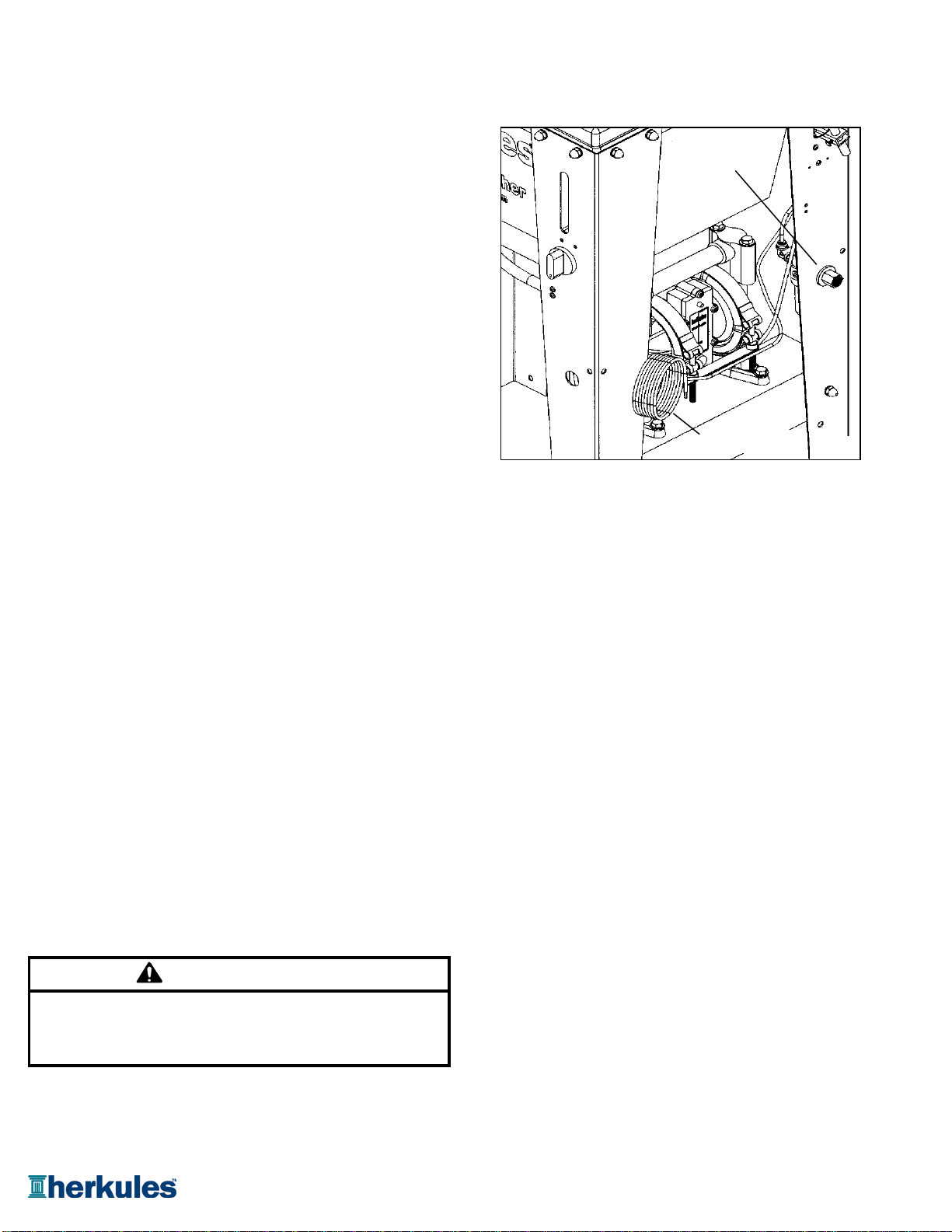
Connecting the Air Line
1) Install a 1/4 in. npt male coupler, that is compatible with
the quick disconnect of your air supply line, into the air-in
port of the filter/regulator, located on the right rear leg [see fig. 8].
2) Connect air line with at least 75 psi to the coupler.
Filter/regulator is preset. DO NOT ADJUST.
Connecting the Cleaning Solution to the Washer Placing Equipment in the Gun Washer
1) Disconnect the drain hose from the flare connector on the To clean guns not mentioned here, use the long or short
bottom of the tank. stem supports as needed [see fig. 10]. For questions or
2) Insert the drain hose and siphon tube into a fresh 5 gallon adapter kits, contact your paint gun washer distributor.
cleaning solution can and secure the plug in the opening.
3) Reconnect the drain hose and tighten. Siphon Feed Guns
4) The can must contain at least 4 gallons of solution to pump Place the gun siphon tube on the short stem support.
properly. Herkules strongly recommends using a high
quality cleaning solution. Gravity Feed Guns (HVLP)
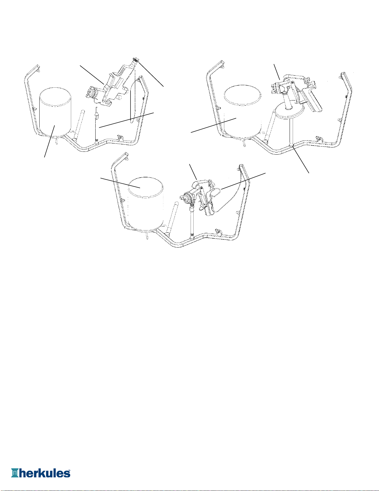
Preparing the Equipment to be washed
Place the long stem support over the short stem
1) Remove paint cup or paint line and the air line from the support. Place paint inlet of gun on long stem support.
paint gun. Place the air cap assembly over the air inlet of the gun to
prevent solution from entering the passage.
2) Drain excess paint from cup and gun. Pressure Feed Guns
3) Remove all gauges and regulators. Place long stem support over the short stem support.
Place paint inlet of gun on long stem support.
4) Lock the gun trigger in the open position by placing the
trigger lock around the gun handle and trigger (see fig.10). Pots and Cups
Place a pot or a cup on the 4-armed platform.
CAUTION
All pressure gauges must be removed before placing the
equipment in the gun washer to avoid damaging the
gauges.
Installation
Operation
Air-in port
fig.8
Ground
Page 10 of 20 Call: 1-800-444-4351
Operating the Gun Washer
1) Make sure wire trigger locks and other accessories 5) If the lid is opened prior to the end of the timing cycle, the
are inside the gun washer tank. safety air cutoff switch will stop the gun washer. The
gun washer will start again when the lid is closed if time
2) Place equipment in the tank according to the diagrams remains on the timer.
shown in fig.10. Note: Open the lid slowly to minimize vapor escape.
3) Close the gun washer lid. 6) Remove the equipment from the gun washer and wipe off
4) Turn the timer knob clockwise 90 degrees to start the gun any remaining cleaning solution.
washer. The gun washer will run for 90 seconds. Turning
the timer knob less than 90 degrees will reduce the timing
cycle. Paint equipment will clean in 60 to 90 seconds.
Operation
Gravity Feed
Gun (HVLP)
Air Cap
Assembly
Paint Cup
Long Stem Support
Paint Cup
Siphon Feed Gun
Short Stem SupportTrigger Lock
Pressure Feed Gun
Paint Cup
fig.10
Page 11 of 20 Call: 1-800-444-4351

Preventive Maintenance
To keep your machine working efficiently, please follow these directions.
1) ALWAYS drain excess paint from cup or pot before placing
in gun washer.
2) Drain paint sludge from gun washer tank weekly. Do this
after a weekend so that it has settled. Open ball valve
and drain until clear solution flows. Add cleaning solution
to fill 1" above intake filter.
3) Replace Filter/Regulator yearly. (#11345)
4) Change cleaning solution completely when objects being
cleaned become tacky to the touch.
5) Clean inside of tub and intake filter before filling with
cleaning solution.
Do not change the setting of the filter/regulator. This could
damage the filter/regulator or pump.
CAUTION
Filter /
Regulator
(11345)
fig.11
Page 12 of 20 Call: 1-800-444-4351

Gun washer will not turn on. 1Make sure the air line is properly connected with at least 75 psi.
(Air pressure is regulated at 75 psi.)
2Make sure lid is fully closed. Make sure the lid rod actuator is making
full contact with the limit valve on the right rear leg.
3 Check all air connections to ensure that there are no leaks.
4 Make sure the timer cam is engaging the limit valve on the right front leg.
5 Make sure timer is on and functioning correctly.
Gun washer turns on but 1 Make sure intake filter is not clogged. If clogged, clean or replace.
pumps slowly or not at all. 2 Make sure the air line is properly connected with at least 75 psi.
(Air pressure is regulated at 75 psi.)
3 Check all air connections to ensure that there are no leaks.
4 Make sure there is at least 4 gallons of cleaning solution in the can.
5 Make sure the siphon hose is far enough into the can to draw cleaning solution.
6Make sure lid is fully closed. Make sure the lid rod actuator is making
full contact with the limit valve on the right rear leg.
7 Make sure manifold nozzles and stem supports are not clogged.
Gun washer will not shut off 1 Make sure timer cam is moving. If it's not, slightly loosen the nuts
holding the limit valve on the right front leg of the stand. Reposition
valve and tighten nuts.
2Make sure limit valves located on the right front leg or right rear leg
of the stand are not stuck in closed position.
Possible SolutionProblem
Troubleshooting
Page 13 of 20 Call: 1-800-444-4351
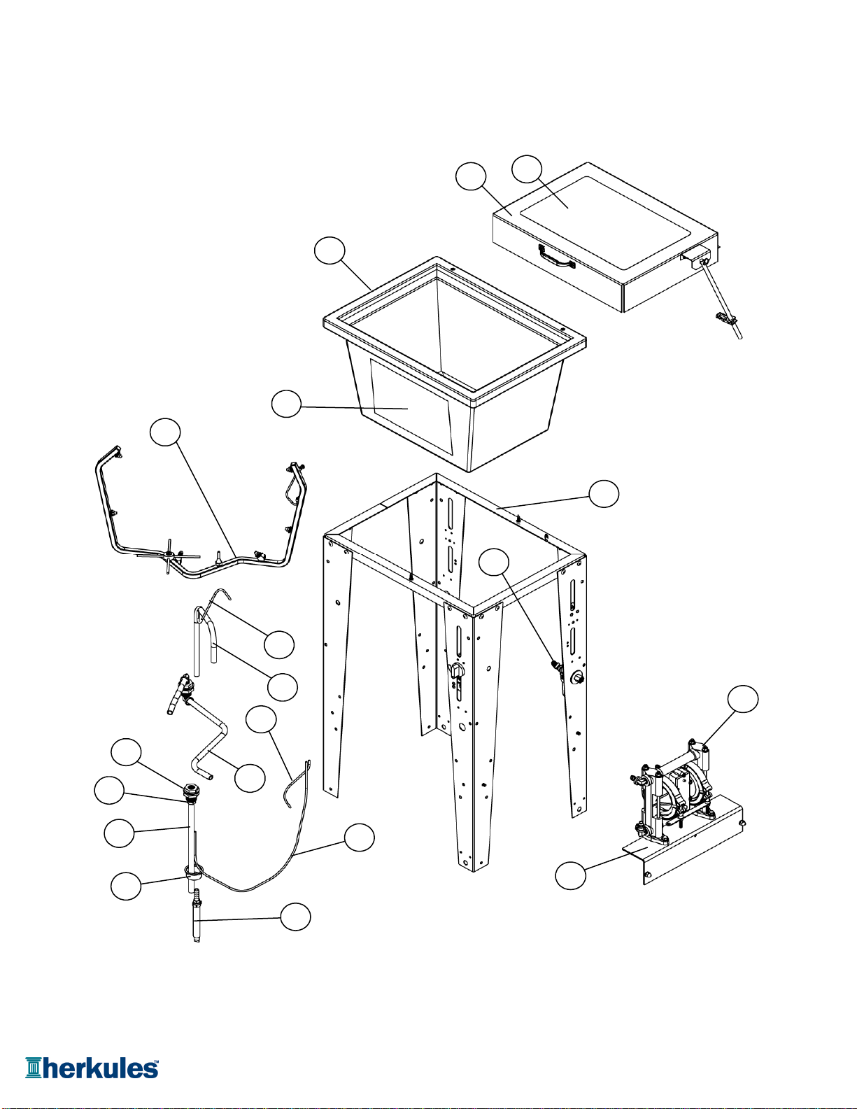
G100 Parts Layout
1
11
4
5
9
3
2
6
12
13
18
17
17
15
14
16
7
8
10
Page 14 of 20 Call: 1-800-444-4351

Part #
Description
1
19278 Tub Assembly 1 ea.
2
1001706 Front Decal 1 ea.
3
11958 Pump Mounting Bracket 1 ea.
4
12129 Manifold Assembly 1 ea.
5
13981 Stand Assembly for G100 1 ea.
6
11243 Filter Assembly 1 ea.
7
1002654 Drain Hose Assembly 1 ea.
8
11130 Plug Slotted - Nylon 1 ea.
9
12018 Pump Assembly 1 ea.
10
11345 Filter / Regulator 1 ea.
11
19279 Lid Assembly 1 ea.
12
1001708 Lid Sticker 1 ea.
13
1002644 Bulkhead with Nut - Brass 2 ea.
14
64PE Hose 1/2 OD x .062 Black PE 16 in.
15
64PE Siphon Hose 1/2 OD x .062 Black PE 23 in.
16
64PE Hose 1/2 OD x .062 Black PE 5.75 in.
17
M5 Tube 5/32 - Blue 27 in.
18
M5-BLACK Tube 5/32 - Black 9 in.
19
M5-NEUTRAL Tube 5/32 - Neutral 11 in.
Note:
For parts shown but not identified
refer to assembly layouts on pages 16-21.
G100 Parts Layout
Quantity
Page 15 of 20 Call: 1-800-444-4351
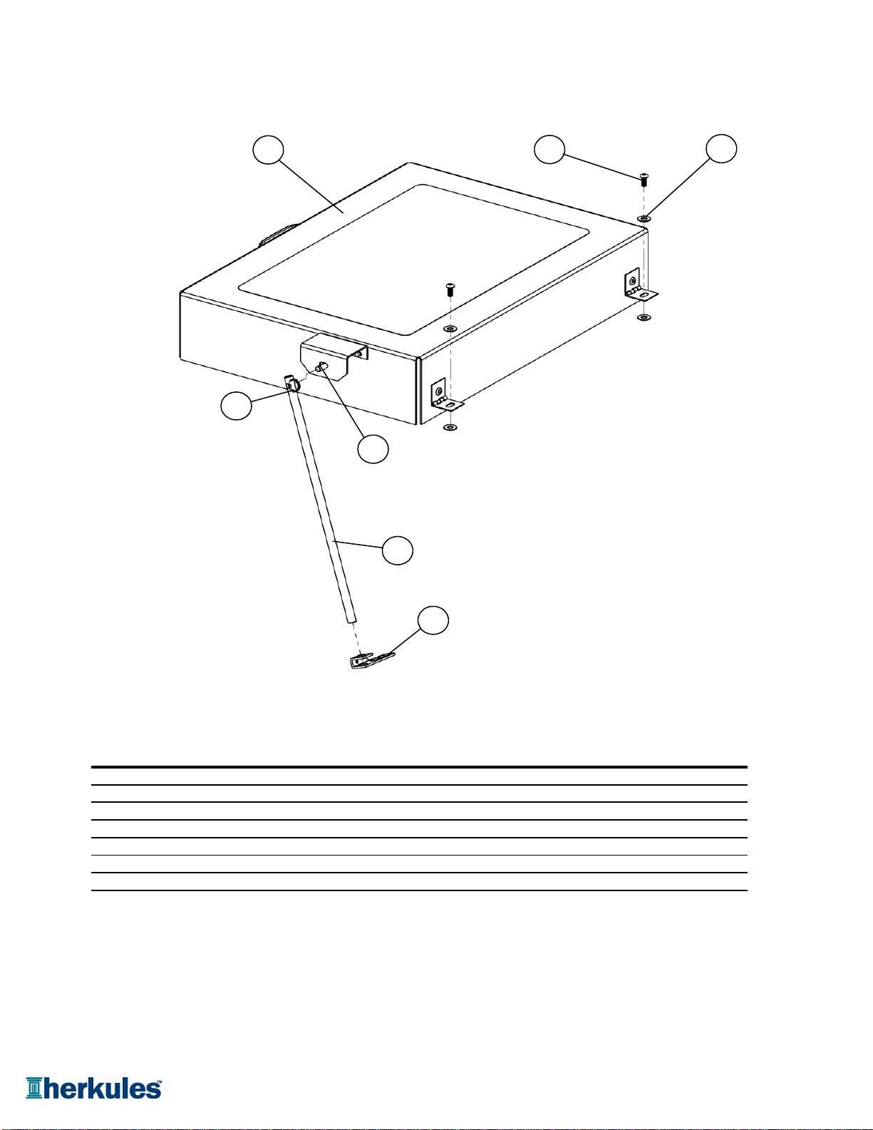
Part #
Description
1
002-161 Washer Flat #10 USS - Zinc 4 ea.
2
19279 Lid Assembly 1 ea.
3
005-155 Screw 10-32 x 3/8 - Black 2 ea.
4
1000252 Cotter Pin 1 ea.
5
1000652 Clevis Pin 1/4 dia. 1 ea.
6
1002571 Actuator Rod 1 ea.
7
11957 Actuator 1 ea.
Note:
Parts are shown for reference purposes only
and are not necessarily part of a Herkules assembly.
Quantity
G100 Lid Layout
1
23
5
6
7
4
Page 16 of 20 Call: 1-800-444-4351
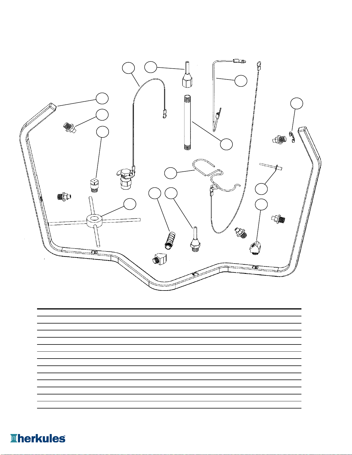
Part #
Description
1
002-121A-6 Manifold Ground Wire 1 ea.
2
002-192 Ground Wire Rivet 1 ea.
3
005-107A Elbow 45° 1/8 NPT - Brass 2 ea.
4
1002422 Cup Holder 1 ea.
5
1002529 Manifold - Stainless 1 ea.
6
1002651 E-ring - Stainless 1 ea.
7
12509 Air Cap Assembly w/ SS Clip 1 ea.
8
22BA Trigger Lock Assembly 1 ea.
9
53A Stem Support Male 1 ea.
10
53B Stem Support Female 1 ea.
11
54P1 Full jet Nozzle - White 5 ea.
12
54 Full jet Nozzle - Brass 1 ea.
13
C9A Nipple 4-1/2" - Brass 2 ea.
14
M27 Hose Barb - Brass 1 ea.
Note:
Parts are shown for reference purposes only
and are not necessarily part of a Herkules assembly.
Quantity
G100 Manifold Layout
12
13
5
1
11
8
9
10
6
2
3
7
14
4
Page 17 of 20 Call: 1-800-444-4351
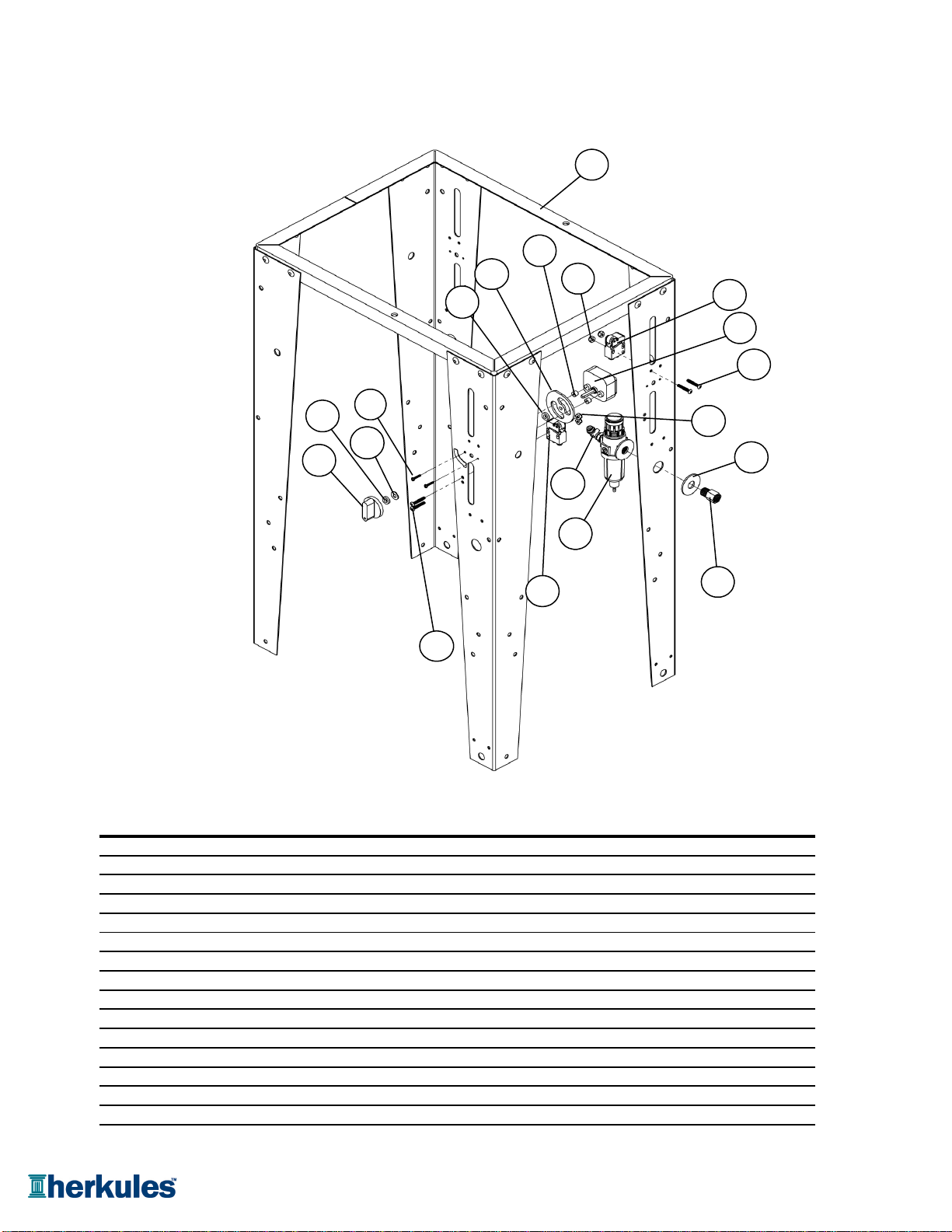
Part #
Description
1
67 Adaptor 1/4 NPT - Brass 1 EA.
2
13981 Stand Assembly G100 1 EA.
3
002-161 Washer Flat #10 USS - Zinc 1 EA.
4
002-171 Screw 8-32 x 1 - Black 4 EA.
5
002-172 Nut Nylock 8-32 - Zinc 4 EA.
6
85I Washer Flat 1/2 USS Z 2 EA.
7
M1C Limit Valve 2 EA.
8
1007592 Timer 1 EA.
9
M230-002 Knob for Timer 1 EA.
10
M230-003 Cam For Timer 1 EA.
11
M230-004 Spacer 1/4" Thick 2 EA.
12
M230-005 Spacer 1/8" Thick 2 EA.
13
M230-006 Timer Screw #4 x 5/8 2 EA.
14
T17M Filter / Regulator 1 EA.
15
T25 Washer Lock Int Tooth #10 Z 1 EA.
Quantity
G100 Legs Layout
2
4
9
13
6
14
15
7
4
8
7
10
12
3
12 5
1
11
5
Page 18 of 20 Call: 1-800-444-4351
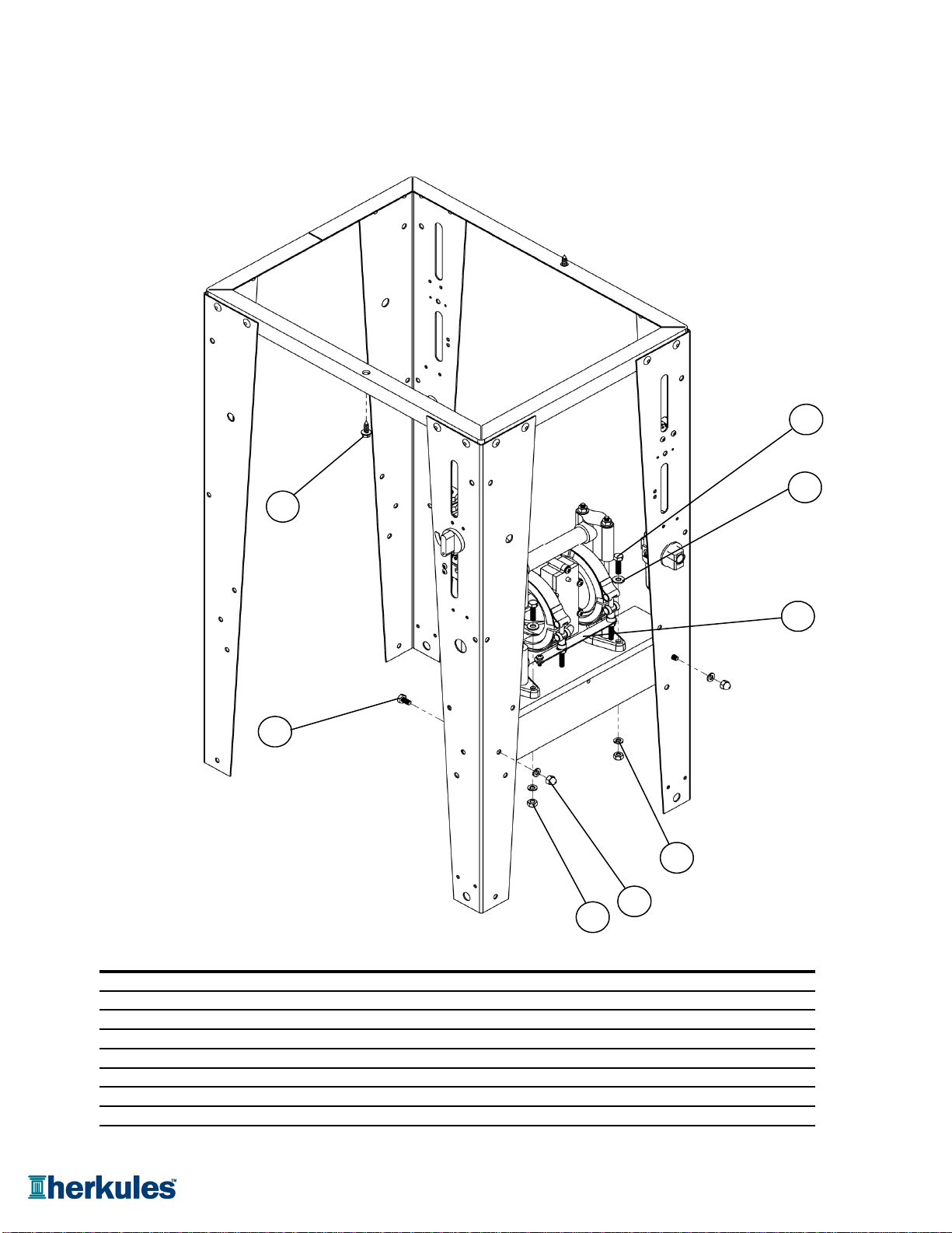
Part #
Description
1
001-705 Washer Flat 1/4 USS - Zinc 2 ea.
2
008-244 Acorn Nut 1/4-20 - Nickel 2 ea.
3
001-702 Bolt Hex 1/4-20 x 1/2 - Zinc 2 ea.
4
83 Bolt Hex 1/4-20 x 1 - Zinc 2 ea.
5
84 Nut Hex 1/4-20 - Zinc 2 ea.
6
85 Washer Lock 1/4 - Zinc 4 ea.
7
002-158 Screw #14 x 3/4 - Zinc 2 ea.
8
12018 Pump Assembly For G100 1 ea.
Quantity
G100 Hardware Layout
1
2
4
3
5
7
6
8
Page 19 of 20 Call: 1-800-444-4351
Page 20 of 20 Call: 1-800-444-4351
Other manuals for G100
1
Table of contents
Other HERKULES Cleaning Equipment manuals


