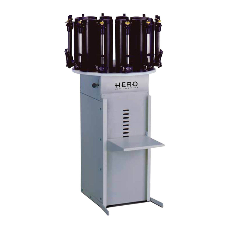
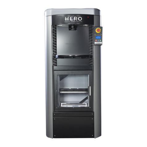
HERO A450 User manual

2
A450 –A460
Automatic Colorant Dispenser
USER MANUAL

3
Congratulations on your acquisition of a HERO Automatic Colorant Dispenser!
The HERO Archimede (A200/A210/A250/A260) and Eureka (A450/A460/A461) lines of
automatic colorant dispensers represent the result of intensive research in the field of high-
tech fluid-dispensing equipment. Top quality materials and modern designing tools such as
the use of CAD three-dimensional parametrical systems, together with the attention given to
ergonomics, guarantee an easy to use and long lasting dispenser.
HERO’s innovative technology is also expressed by its POS dispensing software,
TintWise®. This state-of-the-art Windows based software has been designed to meet the
needs of most operators, combining ease of use and simplicity with extraordinary accuracy
and functionality.
TintWise®, together with an integrated electronic formula book (EFB) and database will
allow you to operate your HERO automatic dispenser as a stand-alone unit. It will also
interface with most third-party color matching systems and spectrophotometers, allowing for
a seamless transfer of EFB and custom formulas to the dispenser.
This Operator’s Manual explains the various features of your HERO automatic colorant
dispenser that will allow you to use it for its ultimate purpose: to dispense colorant formulas
accurately and repeatedly throughout many years of efficient and reliable operations.
Please read this manual carefully and completely. Contact HERO’s 24/7 Help Desk
with any questions: 800-494-4376
This manual should be kept in a safe place

4
Declaration of Compliance with UL, CSA and CE Regulations
HERO Products Group
720 Eaton Way
Delta, BC V3M 6J9
Canada
Declares that:
The Automatic Dispenser model: EUREKA A450 –A460
S
er
i
a
l nu
m
b
er
: ___________
Is in compliance with:
CAN/CSA-C22.2 No. 61010.1-04
Safety Requirements for Electrical Equipment for Measurement, Control and
Laboratory Use, Part 1: General Requirements
Is in compliance with:
UL Std. No. 61010-1 (2nd Edition)
Safety Requirements for Electrical Equipment for Measurement, Control and
Laboratory Use, Part 1: General Requirements
Is in compliance with the EC Machinery Directives:
Machinery Directive 2006/42/CEE
Low tension 2006/95/CEE
Electromagnetic Compatibility 2004/108/CEE
Is in compliance with the standardized European Regulations:
EN 292-1, EN 292-2, EN 418 & EN 1050
EN 60204-1
EN 61000-6-2, EN 61000-6-3, EN 61000-3-2 & EN 61000-3-3

5
EUREKA
Automatic Dispenser Key
Personal
Computer
Electrically
powered can
shelf
Canister cover
Colorant
canisters
Can shelf buttons
Emergency
Stop button
Nozzle
head
cover

6
PC sliding
shelf
Identification
Label
with model and
serial numbers
Cartridge
Pumps
Electronic
Board
(PCB)
Ground
connections
Main switch
and
power
supplier
plug
USB comm.
cable

7
GENERAL INFORMATION
This manual contains information to help an operator to begin using the HERO Eureka
A450/A460 automatic colorant dispenser and insure ease of use and proper maintenance.
Please read this manual carefully and completely before using or servicing your
HERO automatic colorant dispenser.
The Eureka is a simultaneous colorant dispenser that uses progressive cavity volumetric
pumps. Do NOT operate the dispenser or energize any of the pumps without having
colorant in if their respective canisters. Should this occur, the pumps will be
irreparably damaged.
Your HERO automatic colorant dispenser is intended for indoor use only. Do NOT
operate in an outdoors environment.
For proper operation of your HERO automatic colorant dispenser, the following
parameters must be met:
·
Room temperature: 60°F -105°F(
15°C
-
40
°
C)
·
Relative humidity:
30%
-
90%
As with any other electronic device, the Eureka must be connected to a dedicated
electrical outlet and circuit with the proper grounding system. The AC supply voltage
fluctuations may not exceed 10% of the nominal supply voltage.
The specifications for the LED/Laser used in this equipment are as follows:
650 nm, max.1 mW optical power, Class 2 laser (IEC 60825-1), FDA accession number
07R0483-000
Please read the equipment specifications sheet found elsewhere in this manual.
The equipment warranty will be null and void should any of the above mentioned
criteria not be followed.
Please contact HERO’s 24/7 Help Desk with any questions or if you require
any technical assistance:
1-800-494-4376
This manual should be kept in a safe place

8
WARRANTY
Parts Warranty º - year(s) Labor Warranty ¹ - year(s)
HERO warrants its equipment to be free of material and workmanship defects to the original
user, for the period indicated above. This warranty entitles the equipment owner to on-site
parts repair or replacement at no charge under the conditions outlined in this document.
Cleaning and general maintenance are the responsibility of the owner/operator and are not
covered by the warranty. This includes the replacement of certain parts due to normal wear
as determined by HERO.
The warranty is applicable to the original owner and/or location only and is non-transferable
without prior written approval from HERO.
The warranty period begins when the equipment is shipped from HERO’s manufacturing
facilities. HERO may, at its own discretion, start the warranty period at a later date due to
shipping, installation or other delays.
The warranty does not cover damage and repairs due to improper use or non-completion of
recommended daily maintenance procedures, unauthorized service and/or modifications, AC
power problems, or other manufacturers’ interfaced equipment. Damage and subsequent
repairs due to fire and other man-made calamities or any acts of God such as, but not limited
to, floods and lightning, are also not covered. All work completed by HERO due to damage
not covered by the equipment warranty will be billed at HERO’s standard service rates.
I.C.T.C.’s/HERO’s liability is limited to the repair or replacement of parts found to be
defective and does not include other damages or expenses of any kind incurred in
connection with the purchase and operation of the dispenser.
All warranty work requests or claims must be directed to HERO Customer Service at any of
the following:
720 Eaton Way, Delta, B.C. V3M 6J9, Canada
P.O. Box 75, Custer, WA 98240-0075, U.S.A.
Tel: 604-522-6543
Fax: 604-522-8735
Help Desk: 800-494-4376, Option 1
º Parts warranty include shipping via a carrier and service type compatible with the nature of the
equipment failure and as determined by an authorized HERO Customer Service Representative.
When expedited delivery is not warranted, the customer may request and pay for the difference
between such service and HERO’s standard shipping method.
¹ The labor warranty on units covers on-site and travel labor to and from the customer’s location. An
authorized HERO Customer Service Representative must approve all warranty repairs before
any work is performed

9
SAFETY INSTRUCTIONS
Please read the following instructions carefully and completely before installing or
operating your HERO Automatic Colorant Dispenser
I.C.T.C. Holdings Corp/HERO Products Group declines any responsibility should the
following instructions not be followed:
This equipment is designed to be operated indoors only. Do NOT operate outdoors or
in any environment that does not meet the requirements and specifications outlined in
this manual.
Do NOT turn on or operate a damaged machine (for example, if the machine is
damaged during shipping). If in doubt, first contact HERO’s Customer Support Team.
All local, State and Federal safety regulations must be complied with in the
installation and operation of this equipment.
The dispenser and PC must be connected to a dedicated electrical outlet and
circuit with the proper grounding system meeting all the power requirements as
specified on the identification plate.
The owner/operator must maintain the dispenser in good working condition and
replace any broken components in a timely manner.
.
All repairs other than customer maintenance responsibilities must be carried out by
or under the guidance of a qualified technician.
A standard (non-solvent) dispenser is designed and built solely for the purpose of
dispensing water/glycol based colorants. Do NOT use with any solvent based
colorants or any other unauthorized products.
All conditions, instructions and specifications outlined in this manual must be followed
in good faith and any questions or issues must be brought to the attention of a HERO
authorized representative in a timely manner.

10
DISPENSER POSITIONING AND INSTALLATION
Unpacking the dispenser
Remove all shrink wrap from around the container and pallet.
Remove the fastening straps placed around the outside of the box(es).
If a PC is included, removed its boxes from atop the dispenser and place
them in a safe area.
Remove the box around the dispenser by lifting it straight up.
Carefully maneuver the dispenser backwards with two people behind and one
person in front of it, then slowly put the dispenser down on its rear wheels.
Without altering the position of each person, tilt the machine backwards until the
pallet is free and easily removed.
Once the pallet has been removed carefully place the machine down on its wheels.
Instructions for correct positioning
Adhere to the following guidelines when positioning the dispenser:
Place the dispenser on a steady, horizontal (level) surface.
The area must be well ventilated. To prevent colorants from drying, make sure the
dispenser is not exposed to the sun or near heating vents or any other source of
heat.
The ambient temperature should be kept as constant as possible, around 18°C
(always between 15÷40°C) in order to avoid variations in the specific weight and
viscosity of the colorants.
Machine positioning
The Eureka dispenser is fitted out with wheels and levelling feet. When the machine rests
on its wheels and is positioned on a hard and levelled floor it can be easily moved by
pushing it by hand.
Place the dispenser where it is intended to be put to use, then lower the feet and verify
that the dispenser is in a steady, well levelled position.

11
Computer and monitor assembly
The EUREKA dispenser is provided with a
shelf in the upper part of the machine at an
ergonomic height of approximately110
centimetres. The shelf can be used to
position the PC , the LCD monitor and the
keyboard.
After having positioned the PC, it must be
connected to the electronic board that
controls the dispenser. AUSB cable can be
foundand pulledfrom insidethe rear leftcorner
of the dispenser for this purpose.
Pull the USB cable out carefully. If you
encounter resistance call HERO’s Help
Desk. Connect it to one of the USB ports
on the PC

12
Installing the dispenser
HERO automatic colorant dispensers should be installed by trained and authorized
technicians. In addition, a proper installation requires the use of a precision balance capable
of measuring weights between 0.01 and 250 grams.
In the event that a dispenser needs to be installed by someone other than a trained
technician, please follow the instructions in Addendum A accompanying this manual and
contact HERO’s Help Desk with any questions.
The following instructions should be completed in preparing a HERO automatic colorant
dispenser for installation:
Connect the AC power cords of the dispenser and the PC to a dedicated AC power
outlet.
Add 1 or 2 quarts of colorant to each canister without exceeding the maximum
canister capacity.
Colorant should be shook according to its manufacturer’s recommendations but
care must be taken to not operate the dispenser with aerated colorant.
If the colorant needs to be shook mechanically in a shaker or mixer for more than
1 minute, shake it 24 hours before it needs to be put in the dispenser.
Do NOT scrape solidified colorant residue from the bottom of the can into the
dispenser. Mix it with more liquefied colorant in a clean container and stir it
thoroughly until it is homogenized. If it is not aerated, it can then be used in an
automatic colorant dispenser.
Move the PC shelf to one side and open the exposed canister cover.
Find the first canister you want to fill and remove its lid only. Do NOT remove any
other canister lids.
Add colorant to the appropriate canister avoiding the central part of the mixing paddles
as much as possible.
Replace the lid after colorant has been added to a canister and repeat the same
process with all other colorants.
Insure that the dispenser is properly plugged into a dedicated AC circuit and turn on the
power switch on the back of the dispenser where the AC power cord connects.
Check that the dispenser’s emergency button is not activated. It should be pulled out.
You should now hear the dispenser’s agitation motors turn on and by removing one of the
canisters’ lids, you should see its agitation paddles turning. Call HERO’s Help Desk if the
agitation motors do not turn on after powering up the dispenser. The motors should run for
approximately 3 minutes after power is turned on.
Follow the instructions in Addendum A to complete the installation of your HERO automatic
colorant dispenser.

13
CARTRIDGE PUMP REPLACEMENT
When a cartridge pump needs to be replaced complete the following steps:
Disconnect the dispenser from its AC power source.
Remove the lower rear panel on the back of the dispenser.
Remove the wiring connector to the pump’s motor on the pump you want to change.
Use a large flat-tip screwdriver to close the shut-off valve above the pump cartridge.
Some units will have two shut-off valves per colorant. The second shut-off valve is
located in line with the tubing from the bottom of the colorant canister to the pump
housing. This will be a ball type shut-off valve that can be turned off by hand.
Remove the 2 screws that secure the pump cartridge to the pump housing. Do NOT lose
these screws.
(Although you have closed the shut-off valves, it is a good idea to have some towels or
rags ready as you pull the cartridge from its housing). Pull out the pump cartridge from
its housing. You may have to wiggle the cartridge to free it and insure that the
dispenser does not roll towards you as you pull on the cartridge.
Insert a new cartridge pump ensuring that the 2 large “O” rings on either side of the
pump opening and the small “O” ring on the tip of the pump are securely in place.
Secure the new pump cartridge to its housing by replacing the two screws removed earlier.
Reconnect the wiring connector to the pump’s stepper motor ensuring that it is all
the way down with no exposed pins on either side.
Pump shut-off
valve X2
Cartridge Pump
Motor connector
Pump stepper motor
Cartridge
screws X2

14
CARTRIDGE PUMP REPLACEMENT (Cont.)
Clean all colorant residue from the area around the pump. Make sure there
is no colorant on the wiring connector.
Restore power to the dispenser and test the new pump cartridge by
dispensing some colorant. Dispense enough colorant to ensure that all the
air is removed from the line. This equates to approximately 10 oz of product.
Check for leaks and if all is well, replace the rear panel on the dispenser.
Ensure that the power cord and USB cable are not damaged or loose.
UNSTICKING A STALLED/JAMMED PUMP
When a pump stalls or jams creating a loud noise and normally not dispensing colorant,
complete the following steps to attempt to free the pump and return to normal operations:
Disconnect the dispenser from its AC power source
Remove the lower rear panel on the back of the dispenser.
Locate the proper pump cartridge and using the 4 mm key provided with the dispenser, turn
the bolt in the center bottom (facing you) of the stepper motor clockwise. If there is only a
hole and no bolt, thread an M4 (4 mm) X 30 mm screw or bolt into the hole (pump’s drive
shaft-Picture 1) and continue turning it until you feel the pumps’s rotor start to move.
Continue to turn past that point for at least 5 complete revolutions (Picture 2).
Test the pump by dispensing several ounces. Repeat the above process if necessary.
Replace the rear panel on the dispenser. Ensure that the power cord and USB cable are
not damaged or loose.
Reconnect the dispenser to its AC power source.
Pump’s drive
Shaft
Screw/Bolt
M4 x 30
mm
Picture 1
Picture 2

15
AUTOMATIC NOZZLECAP
The Eureka dispenser is equipped with an automatic nozzle cap that is essential in
preventing the nozzle tips from drying or dripping. The cap opens and closes automatically
before and after each dispense. The cup containing the sponge is removed easily, so that it
and the sponge can be cleaned daily.
Inside the cap case there are two micro-switches that control the two positions of the
automatic cap, opened and closed.
The automatic nozzle cap has been designed to be removed or installed easily and quickly. In
order to service or replace it, disconnect the power connector and pull the complete cap
assembly towards the front of the dispenser without letting go of the assembly. As the
position clips release, the cap assembly will fall downward.
To install a new or repaired nozzle cap assembly, align the three position clips with the
three slots on the dispenser’s chassis and push the assembly up and then back until the
clips lock into place. Plug the power connector to the corresponding wiring harness and
test the nozzle cap for proper operation. Position clips
Power connector
It is very important to keep the sponge clean and wet to maintain the nozzle tips in
good working order. HERO recommends that the sponge and cup be removed and
rinsed each morning, leaving the sponge wet with some water in the cup.
Cap
op
e
n
Cap closed

16
TELESCOPIC SHELFACTUATOR
The Eureka automatic dispenser is equipped with a telescopic actuator that raises and
lowers the can shelf. This device allows for the tinting of various size cans along with the
use of the quart/pint locator included with the dispenser as well as the optional pull-out
shelf that can be used with sample (half-pint) cans.
The shelf actuator can be activated using two of the three buttons atop the dispenser. The
green START button on the left side must be pressed while pressing the UP or DOWN
button on the right side.
To remove or replace the shelf actuator assembly, please proceed as follows:
Disconnect the dispenser from its AC power source.
Remove the can shelf by removing the four screws that secure the plate under the
shelf (Picture E).
Remove the four screws that attach the telescopic column to the base plate of
the machine (Picture D). The dispenser will need to be raised or tilted backwards to
reach these screws.
Open the two front doors (or remove the three plastic horizontal panels) on the
lower section of the dispenser. Take care not to damage the wiring and other
electronics inside this area.
Remove the screws securing the mid-level support bracket around the telescopic
actuator and remove the two halves of the bracket (Picture F).
Unplug the electrical connection to the actuator motor inside the telescopic column
and extract the column (pull it up, tilt it to the right and extract it from the left side
carefully).
Picture A Picture B Picture C

17
Place the new telescopic column in the dispenser as shown in pictures A, B and C.
Secure the new telescopic column with the four screws previously removed
(Picture D). The dispenser will need to be raised or tilted backwards to reach
these screws.
Attach the can shelf to the top of the telescopic column with the four screws
previously removed (Picture E).
Reassemble the mid-level support bracket that surrounds the telescopic actuator
with the screws previously removed (Picture F).
Plug in the power connector to the actuator motor (Picture F).
Close the front doors of the machine or replace the plastic horizontal panels.
Reconnect the dispenser to its AC power source.
Picture D Picture E
Mid-level support
bracket
Connector
to
Actuator motor
Picture
F

18
SIMULTANEOUS ELECTRONIC BOARD (PCB)
The simultaneous colorant dispenser allows up to four colorants to be dispensed
simultaneously. The electronic board (PCB) is secured in the dispenser in such a way as to
simplify its removal and replacement.
To remove and replace the PCB, please proceed as follows and refer to the pictures on
the next page:
Disconnect the dispenser from its AC power source.
Remove the lower rear panel on the back of the dispenser.
Carefully pull out the sliding tray holding the PCB and power supplies.
Check that all cables connected to the PCB are properly labeled or otherwise
identified.
Carefully pull out all of the connectors from both sides of the PCB.
Remove the screws that secure the board onto the sliding tray and lift the PCB from
the tray.
Place the new PCB onto the sliding tray and secure it with the screws
previously removed
Plug in all of the connectors ensuring that each numbered harness is connected to
the corresponding numbered connector on the PCB.
Plug in the power supply connectors and the USB cable in their respective
locations.
Carefully pushtheslidingtraybackintothedispenser.
Restore power to the dispenser and test the new PCB by dispensing
some colorant.
If all is well, replace the rear panel on the dispenser. Ensure that the
power cord and USB cable are not damaged or loose.

19
Electronic
board
(PCB)
Sliding
tray
Wiring harnesses
Mounting
hardware

20
DISPENSE TUBE REPLACEMENT
Dispense tubes or hoses connect the output side of the pumps to the corresponding
nozzles in the dispense head located in the upper front section of the dispenser.
To replace a dispense tube, please proceed as follows:
Access the “Empty dispense tube” feature in the TintWise® software by logging in
as “Administrator” and selecting Dispenser utilities / Maintenance (Pictures Gand
H).
Picture
G
Picture

20
Select the circuit that has to be emptied and click on Next.
Click on the OK button in the dispense window (Pictures I and J).
Picture
I
Picture J
Other manuals for A450
1
This manual suits for next models
1
Table of contents
Other HERO Dispenser manuals
Popular Dispenser manuals by other brands

PEGAS
PEGAS CRAFTAP Operation manuals

Coastwide Professional
Coastwide Professional J Series Instruction guide

Manitowoc
Manitowoc Servend Flavor Magic installation instructions

Georgia Pacific
Georgia Pacific PRO enMotion 59466A reference guide

Hoshizaki
Hoshizaki DBF-40SAC Service manual

Katanax
Katanax FLUXPENSER XFP-01 manual