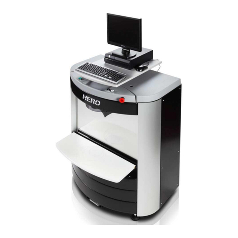
HERO D23 User manual

• D23 • D24 •
• D54 • D55 •
• D60 •
Manual Colorant Dispensers Speed Multi Can Paint Shaker
OWNERS MANUAL

MANL-00005-A - D Series Rotary Dispensers.docx 2
TABLE OF CONTENTS
TABLE OF CONTENTS 2
WARRANTY 4
SAFETY WARNINGS 5
GROUNDING INSTRUCTIONS 6
GENERAL INFORMATION 7
IDENTIFICATION 8
SETUP 13
Package Inspection 13
Assembly 14
Pump Priming 15
Timer 15
OPERATING INSTRUCTIONS 17
Colorant Selection 17
Gauge Setting – Non-micro 17
Gauge Setting – Micro (optional) 17
Dispensing 18
CARE & CLEANING 19
General Guidelines 19
Daily Maintenance 19
Periodic Maintenance 19
SERVICE INSTRUCTIONS 20
Piston Seal Replacement 20
Valve Replacement 22
Gauge Calibration – Non-micro (2 oz. only) 23
New Gauge Calibration – Micro 24
Gauge Recalibration – Micro 24
WIRING DIAGRAM 25
TROUBLESHOOTING 26
SPECIFICATIONS 27
Overall Dimensions 27
Electrical 27
Capacity 27
Canister Material 27
Environmental Conditions 27

MANL-00005-A - D Series Rotary Dispensers.docx 4
WARRANTY
HERO offers a two year parts warranty and one year labor warranty on all of its manual dispensers. The
warranty entitles the owner to parts replacement at no charge. The parts warranty is valid for any
necessary replacement, whether caused by material, workmanship defect or simple wear, except as noted
below.
Electric motors, timers and pneumatic motors warranted for twelve (12) months only.
The warranty is applicable to the original owner only and is non-transferable. The equipment must be
operated and maintained in accordance with all instructions, precautions and warnings contained in the
product manual. For the purpose of this warranty, damage caused by accident, abuse, improper cleaning or
lack thereof, or improper operation, is not covered. Cleaning and general maintenance is the responsibility
of the owner/operator and is not covered by the warranty.
HERO’s liability is limited to the replacement of parts found to be defective or worn and does not include
damage or other expenses of any kind incurred in connection with the purchase and use of the product.
All parts required for warranty service are invoiced to the client, with credit provided upon submission of a
valid warranty claim. A valid claim lists the model number, serial number, date of installation, lists all parts
used and provides for parts installation charges.
Major parts replacement may require the return of defective parts. If uncertain, contact HERO for further
instruction. All returns must be authorized and no return will be accepted without a Return Merchandise
Authorization (RMA) number.
All warranty work requests or claims must be directed to HERO Customer Service at any of the following:
Canadian Mail: 720 Eaton Way • Delta, BC • Canada • V3M 6J9
US Mail: P.O. Box 75 • Custer, WA •USA • 98240-0075
Phone: 604-522-6543
Fax: 604-522-8735
Email: customercare@hero.ca
Help Desk: 800-494-4376, option 1
Parts warranty includes shipping via a carrier and service type compatible with the nature of the equipment
failure and as determined by an authorized HERO Customer Service Representative. When expedited
delivery is not warranted, the customer may request and pay for the difference between such service and
HERO’s standard shipping method.
The labor warranty on units covers on-site and travel labor to and from the customer’s location. An
authorized HERO Customer Service Representative must approve all warranty repairs before any work is
performed.

MANL-00005-A - D Series Rotary Dispensers.docx 5
SAFETY WARNINGS
To avoid electrical shock, unplug dispenser before servicing.
To reduce the risk of electrical shock or injury, use indoors only.

MANL-00005-A - D Series Rotary Dispensers.docx 6
GROUNDING INSTRUCTIONS
This product should be grounded. In the event of an electrical short circuit, grounding reduces the
risk of electric shock by providing an escape wire for the electric current. This product is equipped
with a cord having a grounding wire with an appropriate grounding plug. The plug must be plugged
into an outlet that is properly installed and grounded in accordance with all local codes and
ordinances.
WARNING - Improper installation of the grounding plug can result in a risk of electric shock. When
repair or replacement of the cord or plug is necessary, do not connect the grounding wire to either
flat blade terminal. The wire with insulation having an outer surface that is green with or without
yellow stripes is the grounding wire.
Check with a qualified electrician or serviceman if the grounding instructions are not completely
understood, or if in doubt as to whether the product is properly grounded. Do not modify the plug
provided; if it will not fit the outlet, have the proper outlet installed by a qualified electrician.
This product is for use on a nominal 120-volt circuit, and has a grounding plug similar to the plug
illustrated. Only connect the product to an outlet having the same configuration as the plug. Do not
use an adapter with this product.
Use only a 3-wire extension cord that has a 3-blade grounding plug, and a 3-slot receptacle that will
accept the plug on the product. Make sure that your extension cord is in good condition. When
using an extension cord, be sure to use one heavy enough to carry the current your product will
draw. For lengths less than 50 feet, No. 16 AWG extension cords should be used. An undersized
cord will cause a drop in line voltage resulting in loss of power and overheating.

MANL-00005-A - D Series Rotary Dispensers.docx 7
GENERAL INFORMATION
This manual provides general operating procedures for your manual colorant dispenser. Before operating
the unit or starting any service procedure, carefully read this manual in its entirety. Contact HERO’s
Customer Service Department at 1-800-494-4376 or customercare@hero.ca for assistance, if needed.
HERO D series colorant dispenser are precision measuring devices and should be treated as such. When
operated and maintained in conjunction with the instructions contained within this manual, the equipment
will provide a long and trouble free life. To ensure your complete satisfaction, please familiarize yourself
with all operating and maintenance instructions.

MANL-00005-A - D Series Rotary Dispensers.docx 8
IDENTIFICATION
Adjustable
Shelf
Canister
Assembly
Turntable
Brake Handle
Countertop
Base
Floor Stand
Base
Turntable

MANL-00005-A - D Series Rotary Dispensers.docx 9
Accu-purge
Button
Valve Handle
Plunger Handle
End Cap
Pump Tube
Gauge
Lid
Paddle

MANL-00005-A - D Series Rotary Dispensers.docx 10
Plunger Handle
Setscrew
Dispense
Nozzle
Wiper
Paddle Drive
Shaft
Gauge Lock
Button
End Cap Sleeve
End Cap
Setscrews

MANL-00005-A - D Series Rotary Dispensers.docx 11
Turntable
Drive Cover
Crankshaft &
Washer
Driveplate
Assembly
Turntable Nut
Swivel Body
Drive Bushing

MANL-00005-A - D Series Rotary Dispensers.docx 12
Support Legs
Adjustable
Shelf
Shelf Guides

MANL-00005-A - D Series Rotary Dispensers.docx 13
SETUP
Package Inspection
The D series colorant dispenser has been carefully inspected and calibrated to measure colorant with a high
degree of accuracy. It should be carefully examined upon arrival to determine that the unit shows no signs
of shipping damage. If any parts are found to be broken or damaged, immediately contact the carrier and
arrange for an inspection of the concealed damage. Claims for damage must be made by you, the
consignee, and not the shipper. The carrier accepts full responsibility for the safe delivery of merchandise
upon pick-up from the shipper.
Check the contents as you unpack and if any parts are missing, contact your supplier or HERO
Products Group as soon as possible.
Do not commence set-up until all required parts are available.
Package Contents – Counter Top Models
Turntable
Drive Plate Assembly
Drive Cover
Countertop Stand with attached pre-lubricated crankshaft and washer
Canisters with calibrated gauges
Bag containing canister mounting hardware
Envelop which contained this manual, plus “Lettering”
Bag containing spare parts
•Three nozzle o-rings
•Three spare nozzles (1 each of S, L & XL)
Replacement seal and installation tool
Package Contents – Floor Stand Models
Floor stand models include all of the items from a counter top model plus the following:
Floor stand
Support legs with mounting hardware
Adjustable tray
Bag containing floor stand to countertop stand mounting hardware

MANL-00005-A - D Series Rotary Dispensers.docx 14
Assembly
Refer to the Identification section of this manual to assist with part determination and placement.
1. Prepare an adequate working area to assemble the dispenser.
2. For counter top models, skip to step 6.
3. Place floor stand base assembly into desired location, ensuring base is level.
4. Attach support legs to base of cabinet. Support legs should extend out the front of the base and
away from each other. Secure with provided screws.
5. Place adjustable tray into shelf rails noting the arrows on the nylon guides are pointing up.
6. Install the counter top assembly on to the floor stand and secure with the four screws supplied.
7. Remove the crankshaft and the turntable nut from the center swivel body.
8. Place the turntable onto the swivel body, with the rolled edge of the turntable facing down.
NOTE: Ensure that the turntable rotates freely on the small step on the swivel and not on the threaded
portion of the swivel. Brake should be engaged in the “J” slot to allow constant rotation.
9. Install turntable nut and tighten.
10. Install the pre-lubricated crankshaft complete with nylon washer into swivel body. Ensure the
crankshaft fits completely over the motor’s square drive shaft. The motor drive shaft extends from
inside the floor stand up into the center of the swivel. When positioned correctly the crankshaft
will rest directly on the swivel.
11. Place the drive plate onto the crankshaft, ensuring the crankshaft rotating arm is correctly located
in the center bearing of drive plate. Take note of the “This side up” sticker on the drive plate.
12. Place drive cover over the drive plate.
NOTE: Drive cover must be installed prior to mounting canisters.
13. Rotate turntable until one drive plate arm and a canister mounting location are in line with one
another.
14. Align the canister ensuring that the paddle drive shaft is engaged in the hole of the drive plate
bushing at the end of each arm.
NOTE: The drive plate turns in an oscillating pattern, rather than a circle.
15. With the canister correctly positioned, secure from below the turntable with provided screws. Do
not overtighten.
16. With one canister secured to the turntable, move to the position directly across from it and secure
a second.
17. Continue mounting canisters, rotating the turntable as required.
18. When all canisters are attached, gently rotate turntable. Ensure all paddles are rotating freely and
no binding or chattering is evident.
NOTE:If the paddles fail to complete an entire rotation, the canister drive shaft may not have been
correctly installed in the drive plate. Remove canister and correct.
19. Plug in unit.

MANL-00005-A - D Series Rotary Dispensers.docx 15
WARNING: The dispenser is equipped with an automatic timer that will activate when plugged in. To avoid
accidental breakage or personal injury, ensure all assembly procedures have been completed prior to
plugging in.
Pump Priming
With the unit assembled and canisters mounted, the following steps should be carried out to ensure that
your machine is properly prepared for accurate and trouble-free dispensing. It is recommended that only
one quart of colorant be used for the initial filling and priming. Additional colorant can be added once
proper operation is achieved.
1. Place each can of colorant into a mixer or shaker for approximately five minutes (or as specified by
the colorant manufacturer) to mix any settled pigment.
2. Remove canister lids.
3. Pour the contents of each can of colorant into individual canisters.
NOTE: Apply the canister identification letters to each canister as the colorant is added. Applying the letter
to the stainless steel cylinder is the simplest reference.
4. Set the gauge of each pump to the maximum setting by depressing the spring loaded adjustment
button and lifting the gauge by its handle.
5. Prime each cylinder by lifting the plunger handle to its maximum travel and then pressing it
downwards fully. Do not open the valve during this process.
6. Repeat this plunger stroking process 5 - 6 times to ensure that the pump is completely filled with
colorant and air is worked out of the system.
7. Place a clean can or container under the dispense nozzle.
8. Raise the plunger to its maximum travel.
9. Open the valve by pulling the handle down until it stops.
10. Push the plunger handle down fully to dispense colorant into the cup.
11. Close the valve.
12. Repeat this procedure until the colorant dispenses as a solid stream with no air bubbles.
13. Repeat above procedure for remaining pumps.
14. Return colorants to their respective canisters.
15. Your machine is now ready for use.
Note: Do not add colorant to the canisters while agitation is ongoing.
Timer
Every HERO D series dispenser is equipped with an automatic timer for colorant agitation. The timer
operates for every 10 min every 7 hours at 110V 60Hz or 4 hours at 220V 50Hz. The timer requires no
adjustment or attention on the part of the operator. When shipped, the timer has been set to initiate
agitation as soon as the dispenser is plugged in.

MANL-00005-A - D Series Rotary Dispensers.docx 16
The timer is located on the base next to the power cord. A decal is located next to the timer indicating the
location of the start position. In order to rotate the timer adjustment knob you will require a flat screw
driver. By rotating the adjustment knob the timer can be advanced to the start position. While rotating the
knob a faint clicking sound will be heard. Rotate the dial through the “off” cycle until agitation begins. The
“on” cycle is very short so rotation of the adjustment knob must be done very slowly. You should hear a
loud click during rotation which indicates the “on” position and the start of agitation. Once the ten minute
agitation cycle is complete the timer will then reactivate every seven or four hours.
TO TURN TIMER ON SLOWLY
ROTATE CLOCKWISE UNTIL
FIRST LOUD CLICK
ADJUST TIMER
with flat blade
screwdriver
DAILYROUTINECAREOF THEDISPENSER
It is recommended that the following daily routine be adopted
to ensure trouble free operation of the dispenser.
1. Check the level of the colorant and top-up if required.
2. Set all gauges to maximum dispense. Raise and lower each
plunger without opening valve. Repeat the procedu
re 10 times
slowly.
3. With a damp cloth, wipe down stand, canisters and pumps,
paying particular attention to pump nozzles to prevent
accumulation of excess colorant which may dry out and cause
erratic discharge or blockage.

MANL-00005-A - D Series Rotary Dispensers.docx 17
OPERATING INSTRUCTIONS
Colorant Selection
1. Ensure all gauges are set to zero before beginning.
2. Identify the colorant to be dispensed.
3. Release the table brake and rotate the table until the desired colorant is directly over the
dispensing shelf.
4. Set the table brake to prevent rotation during dispensing.
5. Place an open can of paint under the dispense nozzle.
6. Confirm that there is sufficient colorant in the canister to complete the dispense. If the colorant
level is too low, air will be drawn into the pump during the pump charging process and result in an
inaccurate dispense.
Gauge Setting – Non-micro
TIP: If the dispense formula cannot be completed in a single dispense, multiple dispenses will be required.
In this situation it is recommended to divide the dispense into equal parts to minimize the risk of errors due
to gauge setting.
1. Identify the amount of colorant to be dispensed.
2. Depress the spring loaded button and lift the gauge by its handle to the required marking.
3. Release the spring loaded button and confirm that the gauge is locked in place.
Gauge Setting – Micro (optional)
TIP: If the dispense formula cannot be completed in a single dispense, multiple dispenses will be required.
In this situation it is recommended to divide the dispense into equal parts to minimize the risk of errors due
to gauge setting.
1. Identify the amount of colorant to be dispensed.
2. Depress the spring loaded button and lift the gauge by its handle to the required marking.
3. Release the spring loaded button and confirm that the gauge is locked in place.
4. Turn the micro knob to the desired dispense fraction.

MANL-00005-A - D Series Rotary Dispensers.docx 18
Dispensing
1. With the gauge correctly set, slowly and gently lift the plunger handle until it reaches the gauge
knob.
2. Continue to hold for a few seconds to ensure that the cylinder has completely filled with colorant.
NOTE: Do not open or operate the valve while charging the cylinder or air will enters the system and result
in an inaccurate dispense.
3. With the plunger at the top and the cylinder full, pull the spring loaded valve handle downwards
until it stops and hold in that position.
4. With the opposite hand, push the plunger down completely until it rests on the end cap.
5. Release the valve handle and allow it to return to the closed position.
6. Repeat the dispensing procedure as necessary to complete the formula.
7. Once all required colorants have been dispensed, gently lower the gauges manually to their zero
position.
NOTE: Do not allow the gauges to drop down as doing so can damage them and result in dispensing
inaccuracy.

MANL-00005-A - D Series Rotary Dispensers.docx 19
CARE & CLEANING
General Guidelines
Don’t drop gauges down into end cap. Lower gauges manually back into end cap to prevent
damage.
Keep the machine clean and practice good housekeeping to promote dispensing accuracy.
Do not use the pump as a handle while rotating the turntable. Grab the edge of the turntable to
rotate.
Keep a copy of this manual and the reusable piston seal tool in a convenient place to assist in
regular maintenance.
Do not use metal or other hard objects to clear blocked nozzles as it may result in damage to the
valve.
Keep nozzles clean to prevent blockage from drying colorant. Nozzles are easily removed for
cleaning.
Daily Maintenance
Keeping the nozzle wiper pad, clean and free of dried, dripping or collecting colorant is essential for
trouble-free dispensing. It is recommended that the nozzle wiper arm and pad be cleaned daily with a cloth
dampened with water or mineral spirits.
NOTE: Do not use harsh solvents such as lacquer thinner or MEK as damage may result.
Periodic Maintenance
If the dispenser is not being used on a regular basis, the following should be completed daily:
1. Ensure the canisters are topped up with colorant.
2. Open and close each valve five times.
3. Set gauge to the maximum position and stroke the plunger handle up and down three times.
4. Check valve handles, nozzles, seal arms and pads wear or damage and clean thoroughly.
5. Dispense a small amount of colorant into a clean container and return to canister. To prevent
hardening of colorant in the nozzle and valve, it is essential to have regular colorant movement.

MANL-00005-A - D Series Rotary Dispensers.docx 20
SERVICE INSTRUCTIONS
For technical support, contact HERO Customer Service at 800-494-4376 or customercare@hero.ca.
CAUTION: Remove power to the dispenser prior to performing any service operations.
Piston Seal Replacement
1. Remove gauge from canister.
2. Loosen the two set screws from the end cap assembly and allow sleeve (if equipped) to drop down
around the pump cylinder.
3. Remove the entire end cap / plunger assembly from the cylinder, lifting vertically.
4. Clean colorant from piston assembly.
5. Place plunger shaft in a vice using soft jaws. Do not over tighten the vise.
6. Unthread and remove plunger handle from shaft.
7. Slide end cap assembly off plunger shaft.
8. Remove the screw securing the piston seal to the shaft.
9. Set aside the washer, seal support and screw for later reuse.
10. Discard used seals.
NOTE: Screw is secured with thread locking compound and may be difficult to remove. Ensure the correct
size and type of screwdriver is used to facilitate removal. If unable to remove screw, cut away old seal with
a knife and apply a small amount of heat to the screw to soften the locking compound and allow easier
removal.
11. Remove the new seal from installation tool.
NOTE: The piston seal will begin to expand as soon as removed from the cylinder or tool. If the seal
remains out of the cylinder or tool for longer than 5 minutes, the seal should be inserted into the tool to
compress it prior to installation into the cylinder.
This manual suits for next models
4
Table of contents
Other HERO Dispenser manuals