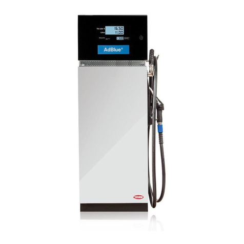
Tokheim OPTimum IQ 6000 User manual

OPTimum IQ 6000
Document Ref 907186-001
Rev - 1
06/2004
Component
Technical Manual

Document Ref 907186-001 Rev 1
OPTimum IQ 6000 Component Technical Manual
Issue A
Great care has been taken in the preparation of this manual however Tokheim
shall not be liable for any misunderstanding, errors and/or loss or defect
arising from the use of this manual.
Tokheim shall not be liable for damage to the product, nor for personal or
third party injury, caused by incorrect use of the product or by attempts to
maintain or to repair the product by parties other than those fully trained by
Tokheim or by its accredited third party representatives.
Please contact your nearest service department, at the relevant address printed
on the back cover of this manual, should any aspect of this manual be unclear.
© Copyright by Tokheim. All intellectual rights arising from, accruing
to,and residing in this manual belong to Tokheim. No part of this document
may be reproduced in any form without the express written permission of
Tokheim.
Tokheim reserves the right to apply changes to this document and the
equipment without further notice.

Document Ref 907186-001 Rev 1 1
Component Technical Manual OPTimum IQ 6000
REVISION RECORD
Date Revision Page Issue Reason
03/06/2004 1 All A Original Issue

2 Document Ref 907186-001 Rev 1
OPTimum IQ 6000 Component Technical Manual
This page is intentionally blank
Issue A

Document Ref 907186-001 Rev 1 3
Technical Component Manual OPTimum IQ 6000
Issue A
CONT.
CONTENTS
1 INTRODUCTION........................................................................................................ 1-2
1.1 How to Use this Manual ......................................................................................1-2
1.2 Product Scope ...................................................................................................... 1-2
1.3 Authorised Technicians ........................................................................................ 1-2
1.4 Contact Information .............................................................................................1-2
1.5 Health & Safety ...................................................................................................1-3
1.5.1 Safety Checklist ...................................................................................1-3
1.5.2 Duties of the Employees ......................................................................1-3
1.5.3 Hazards................................................................................................1-4
1.5.4 Warning Signs ...................................................................................... 1-4
1.5.5 Personal Protective Equipment (PPE) ................................................1-6
1.6 Standards & Certificates ...................................................................................... 1-6
1.7 Nomenclature .......................................................................................................1-7
2 PRODUCT INFORMATION .................................................................................... 2-2
2.1 System Description ..............................................................................................2-2
2.2 Key Characteristics..............................................................................................2-3
2.3 Main Components ................................................................................................ 2-3
2.3.1 Receipt Printer .....................................................................................2-3
2.3.2 Display & Touch Sensor ...................................................................... 2-4
2.3.3 Manual Card Reader ........................................................................... 2-4
2.3.4 Banknote Acceptor (BNA) ................................................................. 2-4
2.3.5 PIN-pad Configurations .......................................................................2-5
2.4 OPTimum IQ Dimensions ....................................................................................2-6
2.4.1 OPTimum IQ Island Terminal Dimensions .......................................... 2-6
2.4.2 OPTimum IQ Island Terminal Footprint .............................................. 2-6
2.4.3 OPTimum IQ BNA Dimensions .......................................................... 2-7
2.4.4 OPTimum IQ BNA Footprint .............................................................. 2-7
2.4.5 OPTimum IQ Retrofit Dimensions ......................................................2-8
2.5 OPT IQ Wiring Diagrams ....................................................................................2-9
2.5.1 Wiring Overview OPT IQ 6000 BIM 2010 .........................................2-9
2.5.2 Wiring Overview OPT IQ 6000 SPIN .............................................. 2-10
2.5.3 Wiring Overview OPT IQ 6000 CRYPTO ....................................... 2-11
3 INSTALLATION OF THE OPT IQ BNA ................................................................ 3-2
3.1 Ground Frame Installation Procedure .................................................................. 3-2
3.2 Lifting and Placement Procedure.........................................................................3-3
4 PARTS LIST ................................................................................................................. 4-3
4.1 OPT-IQ BIM 2010 with Keypad Assembly ........................................................ 4-3
4.2 OPT-IQ SPIN with Keypad Assembly ............................................................... 4-5
4.3 OPT-IQ SBC SPIN with Keypad Assembly .......................................................4-7
4.4 OPT-IQ CRYPTO 100 Assembly ......................................................................4-9
4.5 OPT-IQ CRYPTO 200 Assembly ..................................................................... 4-11
4.6 OPT-IQ SBC Assembly ..................................................................................... 4-13
4.7 OPT Drawer without Keypad Assembly ........................................................... 4-15
4.8 OPT-IQ Support Assembly ................................................................................ 4-17
4.9 OPT-IQ Capacitive Touch Screen Assembly ....................................................4-19
4.10 OPT-IQ Drawer Alarm Assembly ..................................................................... 4-21

4Document Ref 907186-001 Rev 1
OPTimum IQ 6000 Technical Component Manual
Issue A
4 PARTS LIST /
4.11 OPT-IQ Printer Assembly ................................................................................. 4-23
4.12 OPT-IQ Lock Assembly .................................................................................... 4-25
4.13 OPT-IQ Raincover Assembly ............................................................................ 4-27
4.14 OPT-IQ VGA Backlight Assembly .................................................................... 4-29

Component Technical Manual OPTimum IQ 6000
Document Ref 907186-001 Rev 1 Page 1-1
Issue A
CONTENTS
1 INTRODUCTION ......................................................................................................... 1-2
1.1 How to Use this Manual ..................................................................................... 1-2
1.2 Product Scope ..................................................................................................... 1-2
1.3 Authorised Technicians ...................................................................................... 1-2
1.4 Contact Information ............................................................................................ 1-2
1.5 Health & Safety .................................................................................................. 1-3
1.5.1 Safety Checklist .................................................................................. 1-3
1.5.2 Duties of the Employees..................................................................... 1-3
1.5.3 Hazards ............................................................................................... 1-4
1.5.4 Warning Signs .................................................................................... 1-4
1.5.5 Personal Protective Equipment (PPE) ................................................ 1-6
1.6 Standards & Certificates ..................................................................................... 1-6
1.7 Nomenclature ...................................................................................................... 1-7

Page 1-2 Document Ref 908739-001 Rev 1 DRAFT 01
OPTimum IQ 7000 Component Technical Manual
1 INTRODUCTION
1.1 How to Use this Manual
It is recommended that all relevant persons familiarise themselves with the contents of this
manual prior to carrying out any operations or procedures.
This manual is divided into sections which are described as follows: -
Section 1 - Introduction
This section contains information on how to use the manual, the scope of equipment covered,
recommendations on qualified technicians and contact information. It also includes relevant
health and safety information required for the safe practice of common maintenance
procedures.
Section 2 - Product Information
This section contains the system descriptions and operating principles of the various OPT
IQ options including Dispenser Integrated Terminals (DITs), Credit Card Terminals (CCTs)
and Bank Note & Credit Card Terminals (BCTs).
Section 3 - Installation of the OPTimum IQ BNA
This section provides the necessary information for the installation of the OPT IQ BNA.
Section 4 - OPTimum IQ Parts List
This section details the assembly drawings and part identification lists for the various
OPTimum IQ options.
1.2 Product Scope
This manual is designed to cover the OPTimum IQ option in Quantium T-range dispensers.
1.3 Authorised Technicians
Only qualified technicians familiar with the contents of this manual should carry out the
procedures contained herein.
WARNING : ANY ATTEMPTS TO CARRY OUT THE PROCEDURES OF THIS
MANUAL, BY UNQUALIFIED OR UNAUTHORISED PERSONS, MAY RESULT
IN SERIOUS INJURY OR LOSS OF LIFE.
NOTE : THIS MANUAL IS NOT INTENDED TO REPLACE THE SERVICES OF
A FULLY QUALIFIED TECHNICIAN.
1.4 Contact Information
For information relating to the contents of this manual please contact: -
Technical Author
Tokheim UK Ltd.
Dundee, Scotland
For technical assistance please contact the appropriate service division listed on the back
cover of this manual.
Issue A

Component Technical Manual OPTimum IQ 6000
Document Ref 907186-001 Rev 1 Page 1-3
1.5 Health & Safety
1.5.1 SAFETY CHECKLIST
•It is obligatory that this checklist be fully complied with during all work at the
petrol station, particularly construction or repair work.
•It is the duty of the contractor to ensure that all workers employed by him obey
each and all of the relevant laws, directives and other regulations.
Areas where special caution is required
•The insides of tanks, tubes, dome shafts, filling shafts, change over shafts, vessels
and dispensers.
•All areas in which fuel vapour that is heavier than air can accumulate, e.g. fuel
separator, draining shafts, low located rooms, cellars, excavations, pipe trenches
etc.
•The areas around the outlets of tank ventilation pipes, especially during the
filling phase.
•All areas near dispensers, tanker lorries and other vehicles while they are being
tanked up, and particularly when there is a lack of wind.
•A radius of 1.0 metres around petrol carrying pipes, as well as pipes that are not
vapour free.
•Silt traps.
1.5.2 DUTIES OF THE EMPLOYEES
•To ensure optimal accident prevention in our company, in addition to general
rules applying to worker’s protection, it is necessary to take into account all the
national protection of workers legislation and to actively support all measures
which enhance safety standards.
•It is an employee’s duty to follow all company directives regarding the prevention
of accidents, unless such directives can be proved to be unfounded.
•Employees should not follow any instructions that go against safety standards.
•Employees are only permitted to use equipment for its original purpose, and
this is defined by the company alone.
•If an employee detects equipment that is deficient in terms of safety, he shall
eliminate this deficiency immediately. If such safety rectification is not part of
his defined area of activities, or if his knowledge is insufficient to carry out
such work he must immediately inform his superior about the detected safety
deficiency.
This equally applies to:
1) Work Materials which have not been correctly packed or correctly marked in
order to meet safety requirements.
2) Work Methods or work processes which have not been correctly coordinated
or controlled in order to meet safety requirements.
Issue A

Page 1-4 Document Ref 907186-001 Rev 1
OPTimum IQ 6000 Component Technical Manual
3) Where dangerous activities are carried out by several persons, the need for
a permanent faultless communication between them in order to avoid dangerous
events shall require the appointing of one person in order to carry out overall
supervision.
1.5.3 HAZARDS
Prior to starting work, the dispenser must be isolated (i.e. entirely disconnected
from the mains supply) and the mains supply switch locked in the OFF position.
The submerged pump (if applicable) and control signals from the dispenser
must also be isolated. This is done to provide safety for the technician. As a
further precaution, switch off the mains supply in the service station shop and
place a clear notice on the switch to avoid it being turned on again inadvertently.
WARNING : THE CONNECTION AND DISCONNECTION OF
ELECTRICAL CONNECTIONS MAY ONLY BE CARRIED OUT BY
QUALIFIED PERSONNEL AUTHORISED FOR SUCH ACTIVITIES.
WORK IN DANGEROUS AREAS MUST BE MADE SAFE BY
OBSERVING ALL THE NATIONAL SAFETY REQUIREMENTS IN
FORCE.
It is not permitted to put a fuel dispenser into operation before an authorised
official has inspected it and released it. This depends upon the national
regulations in force.
Dismantled packaging and cladding must be stored in such a way as to avoid
damage to components or injuries to persons. Covers that can be opened, such
as the calculator housing, should be handled with care. Ensure that the retaining
catch is placed in the correct position to prevent the cover falling onto the head
of the service engineer or other persons in the area.
At unattended service stations, every end-user should be able to read the User
Instructions. They should be visible on a notice board or integrated into the
DIT and should be sufficiently well lit so that they can be read at night.
At unattended service stations break away couplings must always be used to
reduce the danger caused by a motorist driving off with the nozzle still in the
tank.
1.5.4 WARNING SIGNS
The following warning signs are fitted as standard, on the dispenser, however
they may vary according to individual country requirements or customer
specifications.
Issue A

Component Technical Manual OPTimum IQ 6000
Document Ref 907186-001 Rev 1 Page 1-5
Issue A
Do not use mobile
phones
SIGN
Naked flames and
smoking forbidden
Do not spill fuel on the
ground
Stop vehicle engine
At Diesel high speed
dispensers near the
nozzle boots
Visible from both
sides of dispenser
Visible from both
sides of dispenser
Visible from both
sides of dispenser
Visible from both
sides of dispenser
Trucks only
MEANING POSITION
Do not drive away with
nozzle in tank
Next to User
Instructions near the
nozzle boot
Visible from both
sides of dispenser

Page 1-6 Document Ref 907186-001 Rev 1
OPTimum IQ 6000 Component Technical Manual
1.5.5 PERSONAL PROTECTIVE EQUIPMENT (PPE)
PROTECTIVE CLOTHING
The following clothing should be worn at all times during installation and
maintenance procedures:-
•Protective helmet.
•Protective shoes (conductive).
•Protective gloves and/or protective hand cream.
•Anti static clothing.
•Eye protection.
SAFETY EQUIPMENT FOR WORKING IN HAZARDOUS AREAS
The following safety equipment is required for working in hazardous areas:-
•Only spark free tools are permitted for work on dispensers.
•Work on bearings is only permitted using the standard workshop tools authorised
for this kind of work.
•The use of all electrical tools is strictly prohibited.
•Only the use of explosion protected work lights is permitted.
•The use of telecommunications equipment in hazardous areas is strictly
prohibited.
SAFETY INSTRUCTIONS
The following safety instructions must be adhered to during installation and
maintenance procedures:-
•Inhalation of petrol vapour must be avoided. Suitable precautions must be
taken and where necessary respirators used.
•Avoid direct contact of fuel with the skin.
•Use suitable protective clothing, protective gloves and/or protective hand cream.
•Avoid fuel spills.
•No smoking, no naked flames are permitted.
•Long hair and ties can get caught in moving parts. Hair must be suitably covered.
1.6 Standards & Certificates
Tokheim OPTimum and BNA standalone units are constructed in conformity with the
requirements of all the applicable European Directives (Machinery 98/37/EC; EMC 89/
336/EEC; ATEX 94/9/EC).
Dispenser integrated terminals are incorporated into Tokheim fuel dispensers which
conform to the essential requirements of the Machinery Directive 98/37/EC.
The components used within the OPTimum, including connection facilities, are selected
in accordance with the European Standard EN 50014 (Electrical apparatus for potentially
explosive atmospheres), and the supplementary Standards listed therein.
Issue A

Component Technical Manual OPTimum IQ 6000
Document Ref 907186-001 Rev 1 Page 1-7
The production and end test is controlled through the Quality Assurance systems within
the Tokheim Manufacturing Centres.
1.7 Nomenclature
The various abbreviations used in thie manual are described as follows:-
DIT Dispenser Integrated Terminal
OPT Outdoor Payment Terminal
CCT Credit Card Terminal
BCT Bank Note & Credit Card Terminal
BNA Bank Note Acceptor
Issue A

Page 1-8 Document Ref 907186-001 Rev 1
OPTimum IQ 6000 Component Technical Manual
Issue A
This page is intentionally blank

Component Technical Manual OPTimum IQ 6000
Document Ref 907186-001 Rev 1 Page 2-1
Issue A
CONTENTS
2 PRODUCT INFORMATION ...................................................................................... 2-2
2.1 System Description ............................................................................................. 2-2
2.2 Key Characteristics ............................................................................................. 2-3
2.3 Main Components ............................................................................................... 2-3
2.3.1 Receipt Printer .................................................................................... 2-3
2.3.2 Display & Touch Sensor ..................................................................... 2-4
2.3.3 Manual Card Reader........................................................................... 2-4
2.3.4 Banknote Acceptor (BNA) ................................................................. 2-4
2.3.5 PIN-pad Configurations...................................................................... 2-5
2.4 OPTimum IQ Dimensions................................................................................... 2-6
2.4.1 OPTimum IQ Island Terminal Dimensions ........................................ 2-6
2.4.2 OPTimum IQ Island Terminal Footprint ............................................ 2-6
2.4.3 OPTimum IQ BNA Dimensions ......................................................... 2-7
2.4.4 OPTimum IQ BNA Footprint ............................................................. 2-7
2.4.5 OPTimum IQ Retrofit Dimensions..................................................... 2-8
2.5 OPT IQ Wiring Diagrams ................................................................................... 2-9
2.5.1 Wiring Overview OPT IQ 6000 BIM 2010 ........................................ 2-9
2.5.2 Wiring Overview OPT IQ 6000 SPIN .............................................. 2-10
2.5.3 Wiring Overview OPT IQ 6000 CRYPTO ........................................ 2-11

Page 2-2 Document Ref 907186-001 Rev 1
OPTimum IQ 6000 Component Technical Manual
Issue A
2 PRODUCT INFORMATION
2.1 System Description
The OPTimum IQ 6000 product range is designed to provide pay-at-the-pump facilities
with a country specific user interface. The OPTimum IQ range includes dispenser-
integrated payment terminals and stand-alone island payment terminals for banknote and/
or credit card payment. The range consists of the following:-
•OPTimum IQ Integrated
The OPTimum IQ Integrated is a payment terminal that is
completely integrated in Tokheim dispensers either in the
factory or in the field as a retrofit option for Q400T/500T
range of dispensers. It is also available as option in the
Euro-Premier Dispenser.
• OPTimum IQ Card Terminal
The OPTimum IQ Card Terminal is an island terminal for cards only.
Depending on the configuration, it will be able to accept magnetic-stripe-
cards and/or chipcards. The design combines an excellent presence
without obstructing the view of the forecourt for kiosk personnel. Stand-
alone island terminals are for cards only (no banknotes).
•OPTimum IQ BNA Terminal
The OPTimum IQ BNA terminal is a stand-alone island terminal for
banknotes (and optional credit cards). Depending on the type of
configuration, it can accept up to 20 different banknotes in four
different ways of introduction.
• OPTimum IQ Retrofit
The OPTimum IQ Retrofit is specially designed for field retrofit as an ‘add-on’ unit to
upgrade installed dispensers. Its compact design means it can also be used as an upgrade
for third party dispensers.

Component Technical Manual OPTimum IQ 6000
Document Ref 907186-001 Rev 1 Page 2-3
Issue A
2.2 Key Characteristics
All Outdoor Payment Terminals (OPT) have the following key characteristics:-
• Modular micro-processor hardware
• Off-the-shelf real-time operating system
• High speed thermal ticket printer with automatic cutter and “drop down” ticket bin
• Manual readers for magnetic stripe cards and/or chip cards
• Tokheim Crypto 100 or other security PIN-pads (refer to section 2.3.5)
• VGA color LCD screen with vandal proof touch sensor
• Tokheim proprietary interface to Tokheim site controller
• Modular design harmonised with dispenser design
• Separate mains supply for lighting
• Audio-signal/feedback
• Optional Battery Back-up
• Alarm Contacts
• Optional Privacy shield
2.3 Main Components
The OPT consists of a number of modules which can be combined depending on the type
of the calculator and the number of products and options used. The OPT is supplied with
standard parts (printer and temperature control unit), optional pre-defined parts (card reader
and power supply) and country-specific or customer-specific parts (pinpads etc.).
The main components of the OPT are:-
• Receipt Printer (refer to section 2.3.1)
• Display & Touch sensor (refer to section 2.3.2)
• Card Reader (refer to section 2.3.3)
• Banknote Acceptor (refer to section 2.3.4)
• PIN-pad Configurations (refer to section 2.3.5)
2.3.1 RECEIPT PRINTER
All OPTimum IQ units are fitted with the standard receipt printer, automatic
cutter and printer controller board. A drop-down ticket bin is also supplied to
avoid the risk of paper jams caused by customers removing the ticket prior to
completion of cutting.
The basic characteristics of the receipt printer are as follows:-
• Printing Method : Thermal dot line printing (448 dots per line)
• Effective Printing Width : 56mm
• Printing Speed : 400 dot lines per second
• Paper Feed Method : Friction - Pitch 0.125mm per minute force 100g
• Motor : 4 phase step motor 24V DC (+/- 5%)

Page 2-4 Document Ref 907186-001 Rev 1
OPTimum IQ 6000 Component Technical Manual
Issue A
• Printing Head Circuit : 5V DC (+/- 5% 100mA)
• Printing Head Driving : 5V DC (+/- 5% 1.7A at 25% duty)
• Paper Width : 59.5mm (+/- 5mm)
• Paper Roll Diameter : <113mm
• Temperature Detector : By thermistor
• Head Open Detection : By Mechanical Switches
• Paper End Detection : By Photo Interruptor
• Paper Replacement : Auto Feed (once new roll in position)
•Ambient Temperature -25oC to +50oC
Range : (with direct sun radiation the printer can temporarily
stop working at an ambient temperature of 45oC)
2.3.2 DISPLAY & TOUCH SENSOR
As the displays and keyboards are required to be country-specific, the OPTimum
IQ has been designed accordingly to allow a selection of keypads and displays
to be fitted. In addition to country-specific security requirements, the keyboards
and displays have the following options:-
• 6.4” 1/4 VGA colour screen
• Capacitive touch sensor with toughened anti-glare glass
2.3.3 MANUAL CARD READER
The Card Reader is available for magnetic stripe cards and/or chip cards. The
main characteristics are:-
• Magnetic Cards : Read track 1,2,3 with ISO conformity
• Recording Method : FM decoding (F2F)
• Card Feeding Method : Manual (push/pull)
• Card Feeding Speed : 8-127cm per second
• Service Life : >500,000 passes
2.3.4 BANKNOTE ACCEPTOR (BNA)
For security reasons, Tokheim does not manufacture a dispenser-integrated Bank
Note Acceptor. The Bank Note Acceptor is manufactured as a stand-alone
island terminal with the cash unit located in a specially reinforced compartment
which is not accessible from the installation/service area.
The BNA has the following characteristics:-
• Reinforced money compartment with separate door and safe lock
• Billcoin BNA is supplied with money bag and the Mars Sodeco is supplied
with stacker and cashbox
• Standard reader for up to four different notes (Note : images are stored in
Eeprom); or the upgraded reader which handles up to 13 different banknotes
• Multi-note inlet

Component Technical Manual OPTimum IQ 6000
Document Ref 907186-001 Rev 1 Page 2-5
Issue A
• Anti-magnetic or IC card inlet
• Average acceptance rate of 98%
• Service life approximately 1 million notes
2.3.5 PIN-PAD CONFIGURATIONS
The OPTimum IQ range components vary by country and in accordance with
local and/or national requirements.
SECURITY KEYPAD OPTIONS
BIM 2010
Security PIN-pad with integrated display.
Ambient Temperature Range : -25oC to +50oC
(with direct sun radiation the BIM 2010 can
temporarily stop working at an ambient
temperature of 45oC)
SPIN
Security PIN-pad with integrated display. This
configuration is uniquely for the Belgium market.
CRYPTO 100
Tokheim proprietary capacitive toughened
glass security PIN-pad.
CRYPTO 200
Tokheim proprietary security PIN-pad.

Page 2-6 Document Ref 907186-001 Rev 1
OPTimum IQ 6000 Component Technical Manual
Issue A
2.4 OPTimum IQ Dimensions
2.4.1 OPTIMUM IQ ISLAND TERMINAL DIMENSIONS
2.4.2 OPTIMUM IQ ISLAND TERMINAL FOOTPRINT
Table of contents
Other Tokheim Dispenser manuals
Popular Dispenser manuals by other brands

corob
corob Flex 900 user manual

Kimberly-Clark PROFESSIONAL
Kimberly-Clark PROFESSIONAL AQUARIUS Series instructions

Dolphin
Dolphin DP3114-BTRY manual

Kimberly-Clark
Kimberly-Clark 4913 installation guide

START International
START International Tape TDA080-NM quick start guide

Buffalo
Buffalo GF539 instruction manual