HESA HE400 Guide
MODEL HE400 MICROWAVE BARRIER
(cod. HE400)
INTRODUCTION
The HE400 is a microwave barrier system for external
protection that requires a simple and fast assembly.
The maximum distance of the beam between a
transmitter and a receiver is 200 meters. The HE400
barrier features four field selectable modulation fre-
quencies to allow the installation of barriers within clo-
se proximity and to reduce the possibility of cross link
modulation or mutual interference.
The HE400 barriers requires a low current absorption
(40mA RX, 38mA TX) thus allowing autonomy for a
long period of time with the use of the internal 12 Vcc
– 2,1Ah battery (in each TX and RX units) in case of
mains power failure. This battery gives an autonomy
of over 36 hours.
Description
Each model HE400 consist of one model HE400T
transmitter and one model HE400R receiver, each sup-
plied with universal mounting bracket for pole mod.
HE401 (diameter mm 70-100).
In order to satisfy more specific installation require-
ments, the following accessories for HE400 are avai-
lable as option:
Part number Model Description
HE402 HE402 Horizontal wall mounting
bracket
HE403 HE403 Pole mounting bracket for
diameter 70-110 mm
HE405 HE405 Transformer for powering
one HE400T or HE400R:
230Vac/19 Vac, 30 VA
HE410 HE410 Outdoor container for
HE405 transformer. For pole
mounting use HE403 bracket
HETS400 TS400 Test instrument for HE400
HE19-12 GP2.1-12 12V 2,1 Ah backup battery
for HE400T and HE400R.
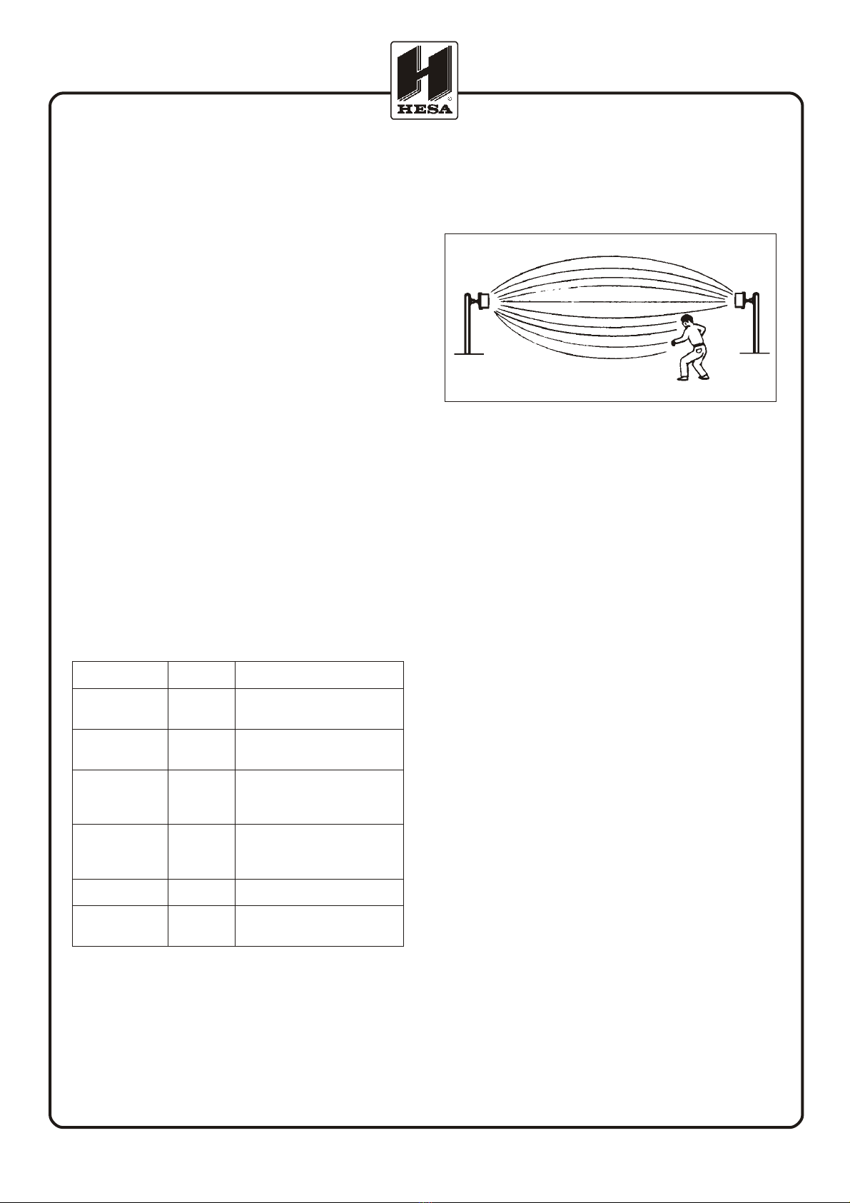
Principles of operation
The transmitter radiates amplitude modulated X-band
energy to the receiver where the received energy is
amplified and processed so that it causes an alarm re-
lay to be energized. When an intruder approaches
the beam, the energy detected by the receiver causes,
if the predetermined level is reached, the relay to be
de-energized and therefore an alarm. Operation of
model HE400 is illustrated in Figure 1. A single model
HE400 may cover a distance up to 200m.
The Receiver incorporates an automatic gain control
circuit (AGC) that adequates the signal to the distance
needed to be covered. Furthermore there are phased
locked loop circuits (PLL) to detect the signal radiated
within a specified frequency band.
Another possibility is the possibility to synchronize the
transmitters: in case two or more TX units have to be in-
stalled on two or more parallel levels in the same di-
rection, a connector is available in order to synchro-
nize the start of the signals radiated to the different re-
ceivers.
Alignment and control
In order to perform a good alignment it is necessary
only a standard voltmeter. On both the receiver and
the transmitter it is available the J2 connector (10 PIN
header) for controlling all the signal and the power
supply levels. We suggest the use of the optional
TS400 Test Instrument Interface that has onboard a
connector, 3 LEDs and buzzer and the connection cab-
le for the J2 header. This interface simplifies the con-
nection of the voltmeter to the barrier. You can even
connect a oscilloscope in order to determine the level
of the received signal.
On the Receiver and the Transmitters boards there are
also 5 LEDs that show the status of the alarm relay, the
presence of the power supply, the correct oscillator
operation and the use of the correct channel between
the TX and the RX.
Model HE400 microwave barrier DT01142 - Page 1
Fig. 1 - Detection pattern
DOCUMENTAZIONE TECNICA TECHNICAL DOCUMENTATION
Installation
HESA advises to make an inspection of the site to pro-
tect considering the following elements:
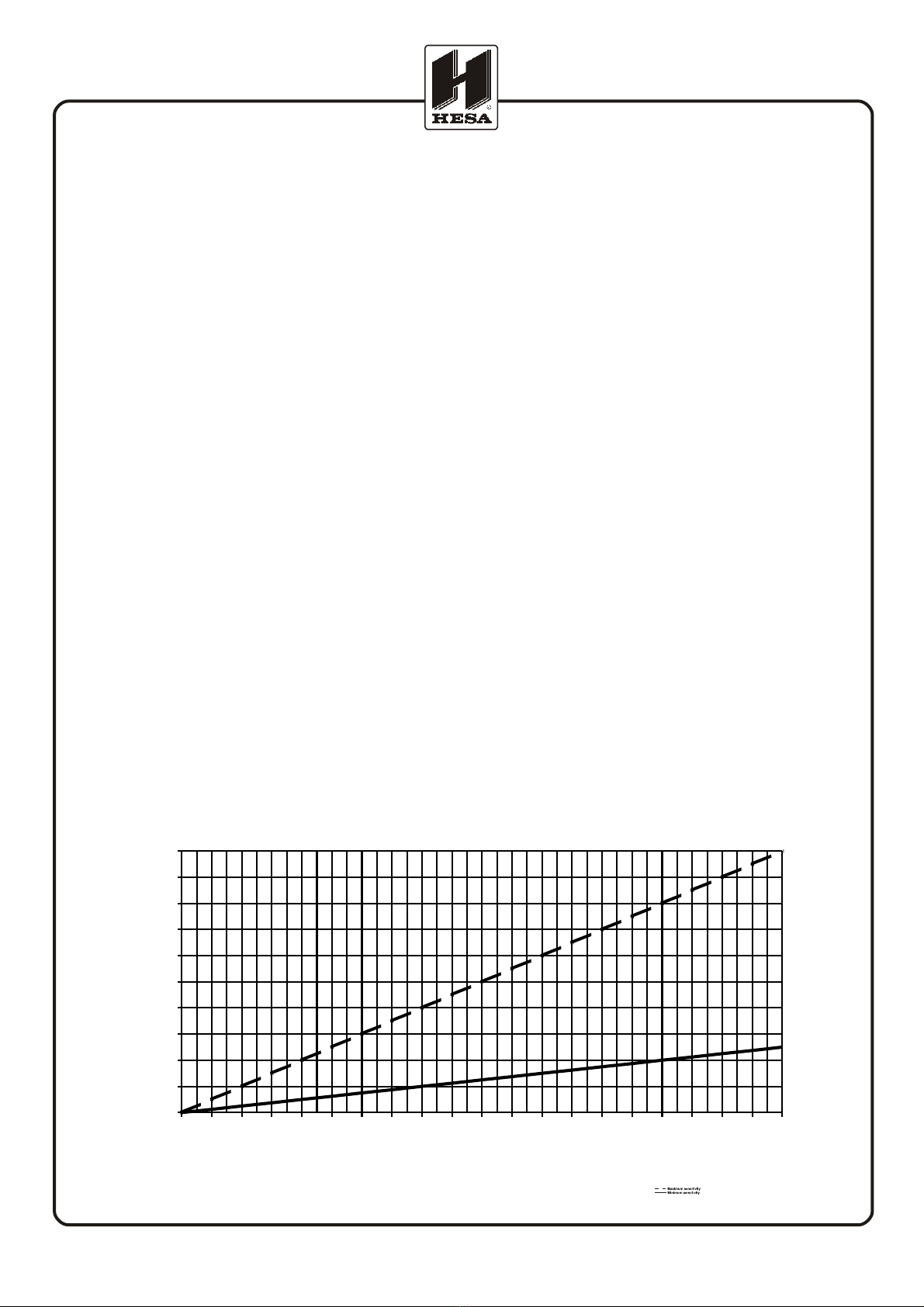
Width pattern of detection area
The width of the beam varies depending on the distan-
ce between the receiver and the transmitter and the
sensitivity level used. The following diagram (Figure 2)
allows you to determine the maximum width of the
beam that is at half of the distance of the barrier.
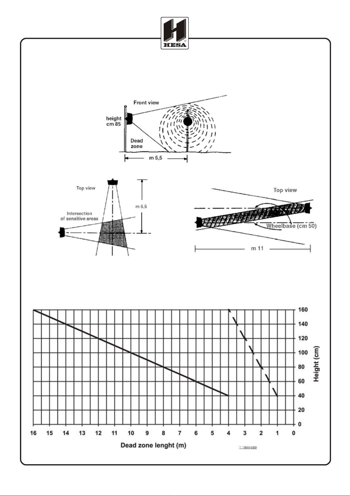
Mounting height
The mounting height from the ground of the barrier de-
pends on the installation requirements but especially
must be determined considering that the increase of
the height increases also the the length of the uncove-
red area that is the area to the ground not covered by
the beam of the barrier. This information is important
also for determining the overlapping of two barriers
that are crossing or that are installed in parallel. Plea-
se note that the uncovered area increases by decrea-
sing the sensitivity (see Figure 4).
Typically the height should be of 85 cm. The
height is between ground and the middle of the devi-
ce.
For security purposes we advise to overlap the ends of
the barriers in order to eliminate the uncovered areas.
Considering an average sensitivity and a mounting
height of 85 cm, you should overlap for about 5,5 m
in the corners and for about 11 m on the rectilinear
protections. In case there are consecutive barriers, the
distance between the centers should be of about 50
cm (see Figure 3).
Model HE400 microwave barrier DT01142 - Page 2
DOCUMENTAZIONE TECNICA TECHNICAL DOCUMENTATION
0
2
4
6
8
10
12
14
16
18
20
10 20 30 40 50 60 70 80 90 100 110 120 130 140 150 160 170 180 190 200
Lun
g
hezza della barriera
(
m
)
Diametro a metà tratta (m)
Fig.2: Diameter of the sensitive zone
Distance between TX and RX (m)
Model HE400 microwave barrier DT01142 - Page 3
DOCUMENTAZIONE TECNICA TECHNICAL DOCUMENTATION
Fig. 4: Installation height of devices
Fig. 3: Attention to dead zones!
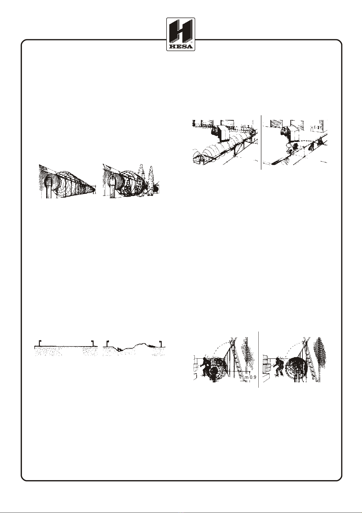
Installation of the HE400 barriers
Required area. Model HE400 barrier must be loca-
ted in an area which is free of moving object such as
chain link fences, trees, bushes and large area of wa-
ter (see Fig. 5). Large moving objects within the protec-
tion pattern will be indistinguishable from an intruder
and will cause nuissance alarms. The clear area requi-
red for a model HE400 installation depends upon the
distance to be covered by the link. In each installation
the cleared area must be at least as large as the pro-
tection pattern.
Terrain. Since operation of the link requires trasmis-
sion of energy from Trasmitter to Receiver, it is impor-
tant to maintain a clear line of sight between the units.
Therefore, the ground must be flat across the protected
area. Any bumps, hills or ditches in the area will
shadow the beam and may provide crawl space for
an intruder. Bumps or hills must be leveled, and
dithches filled so that the area is flat to within 15 cm.
The protected area can be any stable, reasonably
smooth material such as concrete, asphalt, tilled earth,
or gravel. If there is grass or vegetation in the pro-
tected area, it must be kept cut to a maximum of 8 cm
in height. All the bushes or branches must be cut in or-
der to have a free area as large as the clear area.
Physical protection. Install the trasmitter and re-
ceiver in locations which provide protection from acci-
dental damage as well as from tampering. Simple de-
vices such as bumper posts or parking guards may be
used to protect equipment from damage from vehicles
(see Figure 7).
Best security. Choose the location that will provide
best security, yet be free from nuisance alarms. Al-
ways locate model HE400 inside a fence or inside a
controlled access area to prevent unwanted alarms
due to random foot traffic, vehicles, or large animals.
Typically, units should be mounted between 0.75 and
1.0m above ground level and far enough inside fence
to provide a clear area of protection (see Figure 8).
For maximum security it is necessary to overlap the
ends of links so that the dead spot below and imme-
diately in front of the adjoining link is protected. This
type of location gives maximum possible security. A
11m overlap is recommended at intermediate points,
and a 5.5m overlap is recommended at corners. If site
demands shorter overlap, increased sensitivity will re-
duce dead zone, but will also widen beam. The offset
of overlapping links in line should be approximately
50cm; this distance should be measured from center
of each unit.
Connection of the device to the AC
supply
The apparatus work with AC supply at a maximum vol-
tage of 19Vac. The connection between the receiver
or transmitter and the transformer should be the shor-
test possible (less than 4 m) with a wire not less than
1.5mm2. The wires which connect the transformer to
the 220 VDC must have a section of 2.5mm2. In case
Model HE400 microwave barrier DT01142 - Page 4
DOCUMENTAZIONE TECNICA TECHNICAL DOCUMENTATION
Fig. 5: Attention to trees!
YES NO
Fig. 6: Installation on flat grounds only
YES NO
Fig. 7: Avoid interferences with moving objects
YES NO
Fig. 8: Distance from the fence
YES NO

the AC source is low voltage (19Vac), insulation tran-
sformers should be used, 20V: 20V of at least 80VA.
The length of the connection and the possibility that
each device can use a maximum current of 1A must be
considered in the connection to the 19Vac power sup-
ply; in any case the section of the wires must not be
less than 1.5mm2.
Note: The cable which carries the barrier supply from
the transformers to the battery heads must be shielded
and the shield must be connected to the ground.
Connection of the backup battery
Inside each transmitter and receiver unit there is a spa-
ce for installing a rechargeable battery of 12V 2,1
Ah. The battery is charged by the supplier inside each
head and it is connected to it by red and black wires
with supplied with clips wired to the wire terminal. This
battery, when there is no mains supply, allows an auto-
nomy of over 36 hours to the device (when fully char-
ged). If a greater autonomy is necessary, a larger
power supply should be installed very closed to each
device. The connection of these power supply units
should be done at the terminals of the device marked
with the symbols of - and + 13,8 VDC. The sizing of
these groups should done considering that the DC cur-
rent drawn by each single receiver or transmitter unit
is 70mA approx., including the current drawn by the
backup battery.
The following information describe the wiring and the
alignment of the barrier. Please read carefully the in-
formation about the connector J2.
HE400T Transmitter
MS1: terminal block of TX printed board
VAC0/VAC1: power supply, connect the 19 VAC
output of the trasformer.
PT0/PT1: tamper circuit output N.C., for protection
against unauthorized openings, movements or tampe-
ring. In normal conditions there is a NC circuit (0 ohm)
voltage free. The opening of the contact is determined
by a movement of the TX unit (by AMP1) or after a re-
moval of the head cover (change of state of the switch
connected to J3).
SYNC: With JP1 closed (default) in this block there is
the signal for synchronizing other TX units when two or
more TX devices are working near as in the case of a
two levels protection.
-TX Master: close JP1 and make a connection
between the terminal SYNC of the TX Master to the ter-
minal SYNC of the TX Slaves.
-TX Slave: open JP1 and make connection the termi-
nal SYNC of TX Slave to the terminal SYNC of TX
Master.
Important!:
- do not make any connection to the terminal SYNC if
the synchronization feature is not used.
- Use max three TX Slave with each TX Master, total
length 60m max. (total) of wire connection (capacitan-
ce not higher than 150 pF/m).
- The TX Slave units, when synchronized, use the same
frequency of the TX Master.
- Connect together GND terminals of TX Master and TX
Slaves.
JP1: jumper setting for TX Master or Slave. See SYNC
description, connector MS1.
AMP1: movement sensor device. See PT0/PT1 de-
scription, connector MS1.
J3: microswitch connector against unauthorized ope-
nings of the cover of the head. See PT0/PT1 descrip-
tion, connector MS1.
D22: green LED, monitors the 19Vac power supply
presence. Without the power supply and with the bac-
kup battery installed, the LED is turned off but the devi-
ce continues to work normally.
D21: red LED, TX monitors the oscillator. With the
oscillator working correctly the LED is turned off. In
case of an oscillator trouble, the LED is turned on. It is
Model HE400 microwave barrier DT01142 - Page 5
Fig. 9: Transmitter unit circuit board
DOCUMENTAZIONE TECNICA TECHNICAL DOCUMENTATION

turned on also with JP1 open (TX Slave) and without
SYNC signal from the Master TX.
SW1: select one of the four modulation frequencies
for the TX unit; the same feature is found on the RX
heads.
Set TX and RX jumpers at the same positon for proper
function.
J1: TX Antenna assembly connection
J2: TX measure connector.
Pin 1: reference voltage (13,8 VDC)
Pin 2: reference GND
Pin 3-8: not used
Pin 9: TX oscillator reference voltage:
-0 V trouble on oscillator
-9 V normal working
Pin 10: internal reference voltage (9 VDC)
Note:
The voltage on pins 1-2 is also applied to MS2 con-
nector for recharging the backup battery.
It is possible to connect a LED to pin 9 (positive) and
pin 2 (ground) with low current absorbtion (typical
2mA) to monitor the oscillator; in any case, since it is a
CMOS device output, the max current output is 5mA.
MS2: connector for the backup battery; connect the
12V 2.1A rechargeable battery following the polarity
indications marked on the printed circuit; the F1 fuse
(1A) is in series with the positive of the battery.
The battery is automatically charged by the supplier
inside each head. This battery gives the TX an auto-
nomy of over 36 hours in case of mains failure.
F1: Battery protection fuse. See MS2 description.
U2: TO-220 voltage regulator, provides voltage refe-
rence (13,8 VDC). TO-220 metal case is insulated
from the metal case.
General note
The TX electronic board are available with the optio-
nal TEST function and Stand-By mode: see silk-screen
circuit on MS1.
If these functions are active:
TEST: Apply a GND signal (take pin “-“ from MS2) to
activate the test function; the test will be positive if the
correspondent RX will generate an intrusion alarm.
The D20 red LED turns on when the test is active.
STBY: Apply a GND signal (take pin “-“ from MS2) to
activate Stand-by mode of the TX; this inhibits MW si-
gnal emission of TX. Do not modify the JP2 jumper set-
ting (factory default) on the solder side of the PCB.
HE400R Receiver
MS1: terminal block of RX printed board
VAC0/VAC1: power supply, connect the 19 VAC
output of the trasformer.
PT0/PT1: tamper circuit output N.C., for protection
against unauthorized openings, movements or tampe-
ring. In normal conditions there is a NC circuit (0 ohm)
voltage free. The opening of the contact is determined
by a movement of the RX unit (by AMP1) or after a re-
moval of the head cover (change of state of the switch
connected to J3).
ALL0/ALL1: Alarm circuit output NC. In normal con-
ditios the circuit is closed (35 ohm voltage free) while
on the opposite it will be open (R=8). The output is
connected to a photo coupler device and therefore the
maximum current load must be lower than 100mA.
AMP1: movement sensor device. See PT0/PT1 de-
scription, connector MS1.
J3: microswitch connector again unauthorized ope-
nings of the cover of the head. See PT0/PT1 descrip-
tion, connector MS1.
D9: green LED, monitors the 19Vac power supply pre-
sence. Without the power supply and with the backup
battery installed, the LED is turned off but the device
continues to work normally.
D8: green LED, monitors the RX link to the TX signal.
D7: red LED. The LED turns on when an alarm is de-
tected.
SW1: select one of the four modulation frequencies
for the RX unit; the same feature is found on the TX
heads.
Set TX and RX jumpers at the same positon for proper
function.
J1: RX Antenna assembly connection
J2: RX measure connector.
Pin 1: reference voltage (13,8 VDC)
Pin 2: reference GND
Pin 3: 200mV signal. By connecting an oscilloscope
(AC), it is possible to determine the quality of the si-
gnal received; after the normalization period it must
stabilize to 200mVpp ±5%.
Pin 4: not used
Pin 5: threshold value. It indicates the threshold value
set on the RX, selectable by PT5 trimmer.
This value is inversely proportional to the detection
sensitivity and the value must be in the range 0.4-9 V
measured with a digital voltmeter.
Pin 6: RX alarm output reference voltage:
-0 V: not in alarm
-9 V: in alarm
Pin 7: internal reference voltage (5 VDC)
Pin 8: AGC signal: barrier alignment voltage referen-
ce, inversely proportional to the quality of the barrier
alignment.
For the best alignment, the signal must be included
in the range 2,5-6,5 VDC.
Pin 9/10: not used.
Model HE400 microwave barrier DT01142 - Page 6
DOCUMENTAZIONE TECNICA TECHNICAL DOCUMENTATION

Notes on the above listed signals
- The voltage present on pins 1-2 is also used on the
MS2 connector for recharging the backup battery.
- The signal on pin 3 must be monitored in those parti-
cular critical installations where it can happen to have
a strong signal reflection. In normal installation condi-
tions, it is sufficient to align the units using a digital
voltmeter connected to pin 8 (AGC) and pin 2 (GND).
- It is possible to connect a LED with low current con-
sumption (2 mA) directly to pin 6 in order to monitor
the alarm output. Connect to this pin loads lower than
5mA.
- The AGC signal on pin 8 must be measured with a di-
gital voltmeter. Wait at least for 10 seconds between
each alignment test in order to consider valid the mea-
sure.
PT4: Trimmer for adjusting the RX speed detection:
turn clockwise to lower this parameter and on the op-
posite for increasing it (see on the printed circuit for re-
ference signals).
PT5: Trimmer for adjusting the RX sensitivity: turn
clockwise to lower this parameter and on the opposite
for increasing it (see on the printed circuit for referen-
ce signals).
MS2: connector for the backup battery; connect the
12V 2.1A rechargeable battery following the polarity
indications marked on the printed circuit; the F1 fuse
(1A) is in series with the positive of the battery.
The battery is automatically charged by the supplier
inside each head. This battery gives the RX an auto-
nomy of over 36 hours in case of mains failure.
F1: Battery protection fuse. See MS2 description.
U2: TO-220 voltage regulator, provides voltage refe-
rence (13,8 VDC). TO-220 metal case is insulated
from the metal case.
Model HE400 microwave barrier DT01142 - Page 7
DOCUMENTAZIONE TECNICA TECHNICAL DOCUMENTATION
Fig. 10: Receiver unit circuit board
Model HE400 microwave barrier DT01142 - Page 8
DOCUMENTAZIONE TECNICA TECHNICAL DOCUMENTATION
Min. Norm. Max. Note
Working frequency 9.5 GHz 9.9 GHz 9.95 GHz
Maximum power 3 mW
Modulation On/off
Duty-cycle 50/50
Number of channels 4
General internal reference voltage 13.8 VDC
RX current drain in stand-by mode 45 mA
RX current drain in alarm condition 40 mA
TX current drain 38 mA
ALARM OUTPUTS
TX tamper, opening and movement (NC) 30 VA P max
RX tamper, opening and movement (NC) 30 VA P max
RX alarm output (NC) 100 mA I max
CONTROL
RX sensitivity Trimmer
The following statement will be provided with the equipent as required by Article 6.3 of the R&TTE Directive, 199/05/EC:
HE400T is in conformity with all essential requirements of the R&TTE Directive 1999/05/EC. This equipement has been assessed to the following standards:
• Draft ETSI EN 300 440 part 1&2, July 2000
• ETS 300 683: June 1997
• EN 60950: 1992, Incl Amdt 1.4, 11 (+EN 41003/1993)
This product is marked with 0682 wich signifies conformity with Class II product requirements specified in the R&TTE Directive.
Hesa S.p.a. also declare the product HE400, is in conformity with 89/336/EEC and 73/23/EEC directives .
The product. HE400 has been assessed to the following standards:
• ETS 300 683: June 1997
• EN 60950: 1992, Incl Amdt 1.4, 11 (+EN 41003/1993)
!
TECHNICAL SPECIFICATIONS
This manual suits for next models
8
Table of contents
Other HESA Industrial Equipment manuals


