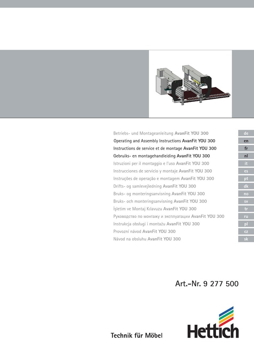
Hettich Blue Max Modular Basic User manual

Blue Max Modular Basic
Blue Max Modular Advanced
Blue Max Modular Basic Plus
Blue Max Modular Advanced Plus
Blue Max Modular Professional
Blue Max Modular
Accessories and Replacement Parts Lists
Technik für Möbel


3
EN
Dear Customer
Congratulations on purchasing our BLUE MAX Modular.
This drilling and insertion machine is a quality German product
with a wide range of different uses.
The BLUE MAX Modular can be used for installing HETTICH
hinge systems and connecting fittings. In addition to this,
the BLUE MAX Modular also gives you the benefits that come
with ‘System 32’ hole lines.
An extensive range of accessories, such as the horizontal drilling
unit, can be added, virtually upgrading the machine into a veritable
all-rounder. Its sturdy, compact design with only a few turning
parts guarantees lasting service.
Depending on model, the BLUE MAX Modular can be used as a
static machine as well as for assembly work in protected
environments on construction sites. Please read these Operating
instructions before you start to use the machine. All of the steps
involved in setting and operating the machine are described below
in exact detail, making your work with the BLUE MAX Modular very
easy right from the word go.
We hope the BLUE MAX Modular brings you lasting satisfaction
and wish you every success working with it.
Please observe the safety precautions on the pages that follow.
January 2009

4EN
1.0 Contents
Page
1.0 Contents 4
2.0 General Safety Precautions 5 - 6
3.0 Equipment Level Supplied 7
4.0 Installation and Connection 7
4.1 Assembly 7
4.2 Remove transport brace from drilling head 7
4.3 Install hand wheel and toothed belt 7
4.4 Connecting to suction extraction system 8
4.5 Connecting to the compressed-air supply 8
4.6 Connecting to the power supply 8
4.7 Setting up the machine 11
5.0 Praparing for Work 11
5.1 Setting drilling depth (vertical) 11
5.2 Setting drilling height and depth (horizontal) 11
5.3 Mounting and changing the drilling unit 12
5.4 Drill chuck / changing drill bits 13
6.0 Operating the Machine 14
6.1 Pushbuttons and switches 14
6.2 Stops / hold-down clamps 16
6.3 LC display 16
6.4 Position drilling units / caterpillar drive 17
6.5 Vertical drilling / indexing stops 19
6.6 Horizontal drilling 20
6.7 Drilling System 32 hole lines 20
6.8 Drilling holes for fittings and inserting fittings 21
6.9 Setting drilling stroke 21
7.0 Accessories and Replacement Past Lists 24
7.1 List of accessories 24
7.2 Drilling pattern,
interchangeable drilling unit, hinge 25
7.3 Drilling pattern,
interchangeable drilling unit, System 32 25
7.4 Installing the foot switch 26
7.5 Installation Instructions:
Accessory Continuation Stops 26
7.6 Installation Instructions:
Accessory Press-In Frame 27
7.7 Installing the Arm Extension 28
7.8 Installation Instructions: Accessory
Press-In Frame for Combination Drilling Unit 29
7.9 Installation Instructions:
Combination Drilling Unit 30
7.10 Installation Instructions:
Additional Hold-Down Clamp 30
7.11 Drilling pattern for 31
7.12 Drilling pattern for 31
8.0 Replacement Parts Lists for Blue Max Modular 32
8.1 Basic 32
8.2 Basic Plus 32
8.3 Advanced 33
8.4 Advanced Plus 33
8.5 Professional 34
8.6 Assembly 1A (basic frame) 34
8.7 Assembly 1B (basic frame, small) 35
8.8 Assembly 2 (workpiece clamping) 35
8.9 Assembly 3A/3D (Z-axis) 36
8.10 Assembly 3B (drilling-unit mount) 37
8.11 Assembly 3C (drilling-depth adjuster) 37
8.12 Assembly 4 (fence) 38
8.13 Assembly 5 (work bench) 38
8.14 Assembly 6 (work-bench extension) 39
8.15 Assembly 7
(transversal adjustment with LC display) 39
8.16 Assembly 8 (fence without depth adjuster) 40
8.17 Assembly 9 (work bench tool slide) 40
8.18 Assembly 10 (work-bench extension, tool slide) 41
8.19 Assembly 11 (X-axis with LC display) 41
8.20 Assembly 12 (X-axis adjustment
by toothed belt and hand wheel) 42
8.21 Assembly 13
(revolving fence with individual cams) 42
8.22 Assembly 14 (caterpillar drive –
only possible with assembly 13) 43
8.23 Assembly 15B (horizontal drilling unit) 43
8.24 Assembly 18 (operator’s control box) 44
8.25 Assembly 24
(suction extractor, vertical drilling, "moving") 44
8.26 Assembly 23
(suction extractor, horizontal drilling) 45
8.27 Assembly 26 (suction extractor,
horizontal drilling under moving axis) 45
8.28 Assembly 19 (pneumatic system
"lock transversal adjustment") 46
8.29 Assembly 20 (controller for
individual cams – possible with assembly 18) 46
9.0 Replacement Part Lists for Drilling Unit 47
9.1 Spindle types
(AS=drive spindle / BS=drilling spindle) 47
9.2 Basic plate for drilling units
(not for horizontal drilling unit) 49
9.3 Hinge unit, 3-spindle type 49
9.4 Adapter unit 3+1-spindle type 50
9.5 Drilling unit, 5-spindle type, vertical 50
9.6 Drilling unit, 5-spindle type, horizontal 51
9.7 Drilling unit, 8-spindle type, combination 51
9.8 Drilling unit, 9-spindle type 52
9.9 Drilling unit, 19-spindle type 52
10.0 Care and Servicing 53
10.1 General information on servicing 53
10.2 Lubricating the drilling unit 53
10.3 Water separator 53
11.0 Troubleshooting 54
11.1 Fault, causes and remedies 54
12.0 Technical Specifications 55
12.1 Electrics 55
12.2 Weights and dimensions 55
12.3 Noise emission 56
12.4 Suction extraction system 56
12.5 Compressed-air connections and
pneumatic circuit diagrams 56
12.6 Electric circuit diagrams 62
12.7 EC Declaration of Conformity 67
Subject to change without notice!
Seite

5
EN
2.0 General Safety Precautions
You must read and follow these safety precautions before
assembling and starting up the machine.
Product liability legislation requires the manufacturers of machinery
to include comprehensive safety precautions in their operating
instructions. These are intended to draw the attention of the owner
of a machine to so-called residual risks and help to operate the
machine safely.
Operating the machine safely
The machine is a semi-automatic machine for drilling board-type
workpieces and inserting the hardware intended for them.
A detailed description of how to do this may be found in the
operating instructions. Any use other than or extending beyond
this is deemed to be improper use. The manufacturer/supplier
is not liable for any damage resulting from improper use.
– The risk is borne solely by the user!
Proper use also includes observing the operating instructions and
adhering to the inspection and servicing intervals. This machine is
built in accordance with the state of the art and recognised code of
safety. Nevertheless, this machine may present hazards if operated
incorrectly. In particular, this includes improper use and/or operation
by persons who have not received proper training or instruction.
This poses a threat to life and limb for the user or third parties.
Any person operating, servicing or repairing this machine or
entrusted with changing its settings must have read, understood
and observed the operating instructions and, in particular, the safety
precautions! The authority and tasks of personnel operating this
machine must be clearly defined. The following pages contain
information which, provided it is followed, may reduce the
residual risks.
This list is not exhaustive and does not relieve users of the
responsibility to develop their own code of safety and safe
working methods.
A) This machine must only be operated by properly
instructed persons.
1. Responsibilities at the machine must be clearly defined. The
machine operator must not allow the machine to be operated by
non-instructed personnel. Instructions posing a threat to working
safety must be rejected!
2. Before leaving the machine, it must be switched off. Never allow
machines to run unattended! Unplug the machine, disconnect it
from the compressed-air supply and remove the drill bits.
B) Application
This machine must only be used for working on flat board
made of wooden materials, such as particle board,
blockboard, MDF, solid wood or similar board!
The manufacturer accepts no liability for other uses.
1. Any misuse of assemblies set up on the machine,
e.g. working on hand-held or unreliably clamped
workpieces, poses a risk of injury.
2. Without consent, the machine must not be modified by adding
non-OEM attachments of relevance to safety or by adding other
equipment.
3. Minimum and maximum workpiece dimensions:
Length: 300 mm – 2500 mm
Width: 70 mm – 750 mm
Thickness: 12 mm – 50 mm
4. Max. wood moisture must be between 8 and 12 %.
5. Exercise particular caution when working on workpieces that
project beyond the work bench. In this case, fit a larger work
bench or larger supports.
6. Secure the workpiece while you are working on it.
Use the hold-down clamps.
C) Tools
Only use tools that have been tested and are of the type
suitable for mechanical feeding! Attach tools securely!
1. Observe information provided by manufacturers of tools with
clamping systems (also refer to the section on changing drill bits
in the operating instructions).
2. Only use properly sharpened drilling tools.
3. The maximum tool diameter on the vertical drilling
unit is 40 mm.
4. The maximum tool diameter on the horizontal drilling
unit is 10 mm.
D) Operating instructions
Observe the operating instructions!
1. This is where you will find further information on work safety
and accident prevention.
2. Personnel entrusted with activities on the machine must
have read and understood the operating instructions,
in particular the section on safety, before commencing work.
It is too late once work is in progress! This applies in particular
to persons who only work on the machine occasionally,
e.g. for setting it up or servicing it etc.
3. Operating instructions must be kept available at the machine at
all times!
E) Safety regulations
Observe accident prevention regulations!
1. Observe the further pertinent regulations on preventing
accidents and protecting the environment!
2. In addition to the operating instructions and the rules in
force and binding in the user’s country on preventing accidents,
it is also necessary to follow the recognised code of safety and
proper work practice.
3. Refrain from any actions that pose a threat to safety!
F) Area surrounding the machine
Avoid crushing hazard when operating the machine!
1. Allow a clearance of at least 500 mm between moving machine
parts and columns, parts of the building, cabinets etc.!
2. Do not place any pallets in this safety zone!
G) Work clothing
Wear suitable work clothing!
1. Wear safety goggles and hearing protection while working at the
machine.
2. Do not wear loose work clothing; if applicable, employ suitable
means to protect long hair.
3. Risk of being pulled in by moving machine parts!
H) Safe behaviour / Advice on residual risks.
Do not reach into the machine when it is running!
1. Residual risks under EN 292-2: The machine conforms to the
safety requirements currently in effect. Nevertheless, residual
safety risks still exist. This is why it is necessary to read the
operating instructions carefully and observe the safety
precautions.
2. Do not conduct quality inspections on the machine while it is
running!
3. Do not reach into machine while it is running, behind the
cladding or into places that are hidden from view!
4. Do not perform any actions with your hands in the
hazard zone of the hold-down clamp – crushing hazard!
5. Do not perform any actions with your hands in the
hazard zone of the caterpillar drive – crushing hazard!
6. Do not perform any actions with your hands or objects in the
area of the drill bits or press-in frame while the drilling or
insertion cycle is in progress.
7. Hazard – you could crush and cut your hands!

6EN
I) Safety zone
Do not reach into the machine’s working zone while the
machine is running!
1. Crushing hazard!
ATTENTION!
Never allow a second person to enter the safety and working
zone. Never let a second person switch the machine on!
2. The machine must always be operated and recharged with
fittings from the front.
ATTENTION!
3. While work is in progress at the machine, no other persons
must be present in the safety and working zone in front
of the machine and behind it.
Crushing hazard!
4. Do not reach into the working area of the clamping cylinder and
drilling unit during production. Appropriate aids must be used
for pushing small parts up to the stops.
J) EMERGENCY STOP
Only actuate the EMERGENCY STOP switch if there
is a risk of accident!
1. The EMERGENCY STOP switch is only a safety device for the
protection of persons. Do not use this switch for halting
operation in general.
2. In the event of machine malfunctions, always unplug the
machine first, disconnect it from the compressed-air supply and
remove the drilling unit!
K) Safety devices
Pay attention to safety devices!
1. Do not remove the factory-fitted safety devices, safety hoods
and switches. All safety and hazard warnings at/on the machine
must be kept in legible order.
2. Do not render any of the safety devices ineffective.
3. If it is necessary to remove safety covers for changing tools or
for cleaning and servicing, it is imperative to refit them before
returning the machine to operation! Check for proper working
order.
4. Operating the machine without these covers will result in
hazards from flying chips and allows persons to reach
unintentionally into rotating tools or crushing zones.
L) Repairs and servicing
Only perform servicing and repair with the machine
switched off!
1. Operating personnel must be notified before carrying out
servicing and repair work.
2. When performing work inside the machine or on the electrical
system, always turn the main switch off first, unplug the
machine, remove the tools and disconnect the machine
from the compressed-air supply!
3. When removing or installing assemblies with lifting gear,
make sure lifting gear is safe as well as carefully and properly
attached.
4. Repair and servicing work, in particular to the electrical
equipment, must only be performed by a qualified,
skilled person.
5. Work to the electrical system must only be performed
by experienced and trained personnel.
6. Only use fuses of the prescribed rating; fuses with ratings
that are too high will cause irreparable damage to the system.
If fuses frequently blow, locate the cause and rectify the fault
before switching back on again.
7. Only use lubricant grades designated by the manufacturer.
When handling oils and greases, observe the safety regulations
applicable to the product concerned.
8. Only use genuine replacement parts from the manufacturer or,
in the case of standard parts, parts of equal quality.
9. Clean the machine by vacuuming off dust and chips.
10. Before working on the pneumatic system, always switch
off the main switch first, unplug the machine, remove the tools,
disconnect machine from compressed-air supply and clean.
Carefully detach any hoses that need to be disconnected;
escaping compressed air can stir up dust and chips.
Keep hoses and air connections free from internal soiling,
covering them or plugging them off if necessary.
11. When performing repair work to the drilling units, do not mix
up air hoses or plugs of switches. This will result in malfunctions
and hazards from tools in the extended positon.
Keep to the manufactuer’s routing regime, use hose clips.
M) Noise!
Wear hearing protection!
1. Wear hearing protection when performing very noisy work
processes.
N) Dust
Health hazards from wood dust!
1. The machine complies with dust protection regulations when
operated with the intended suction extraction facilities.
2. Some work processes and specific workpieces (e.g. door frames,
fascias or special profiles) do not permit full encapsulation and
suction extraction.
Wear dust protection masks!
O) Remnants
Configure workpieces in such a way as to prevent remnants
from being hurled into the air.
P) Machining forces
Select feed rate and cutting volume to suit the holding
force of the clamping devices and workpiece material!
1. See setting for drilling speed. If workpieces are a problem to
hold in place, use additional stops, templates or power clamps.
Q) Fire hazard
Grinding and welding work only with machine in a clean
state; fire hazard!
Observe welding regulations and accident prevention
regulations.
R) Explosion protection
Machine is not explosion-protected.
Do not install in the proximity of painting facilities!
S) Malfunctions
The machine operator must inspect the machine
for externally visible defects on a daily basis.
1. Defects must be rectified without delay or, if other personnel
is responsible for remedying them, reported requesting repair.
2. The machine must only be operated in perfect working order.
3. The area around the machine must be kept clean and free of
tripping hazards. Air hoses and extraction hoses must be routed
so as not to restrict the movement of the machine operator.
4. The specified servicing work must be performed at the intervals
stated. If applicable, the owner must specify other appropriate
intervals or list additional work.

7
EN
4.0 Installation and Connection
The BLUE MAX is shipped in damage-prevention packaging. Some
parts must be installed to make the machine ready for operation.
After setting up the machine, remove any dust collected in transit
and clean off preservative agents (oil).
4.1 Assembly
After you have screw-mounted the machine to the work bench
at the holes provided (see supplementary sheet on "Unpacking"),
please proceed as follows:
4.2 Remove transport brace
from drilling head
(Basic Plus, Advanced Plus, Professional)
The drilling head is braced with a threaded rod that must
be removed before start-up. To do this, please undo the nuts
(yellow arrows) on the threaded rod and remove both.
Equipment level supplied
Work bench, 800 mm XX
Work bench, 3000 mm XXX
Depth adjustment facility (Y-axis), 0 - 100 mm X X
Depth adjustment facility (Y-axis), 0 - 550 mm, with LC display X X X
Lengthways adjustment facility (X-axis), 0 - 2200 mm, (toothed belt/hand wheel) with LC display X X X
Revolving fence with individual cam XXX
Caterpillar drive X
Operator’s control box with additional functions XXXX
Extractor hood with turning mechanism (allowing the drilling unit to be turned through 90°) X X X
Basic
Basic Plus
Advanced
Advanced Plus
Professional
4
SW 13
4.3 Install hand wheel
(Advanced, Advanced Plus, Professional)
In the box of accessories you will find the hand wheel.
Take it out and fit it using a 3mm hexagon socket spanner.
3.0 Equipment Level Supplied for Blue Max Modular Types
From the front,
push the hand wheel onto
the projecting pin and secure it in place by
tightening the grub screw on the machine-cut face.
6
4
6

8EN
4.4 Connecting to suction
extraction system
Connect the machine to a suction extraction system. Connection
to a suction extraction system is compulsory and must be done
using a flexible hose of flame-retardant quality.
Push the extraction hose (see table below for diameters) from the
suction extraction system onto the extractor hose connector and
fix it in place with a hose clamp. The suction extraction system’s
air flow rate must be at least 20m/s.
Blue Max Modular Type Extractor hose connector on Extractor hose connector on Volume flow
vertical drilling unit horizontal drilling unit (per hose connector)
(outer Ø) (outer Ø)
Basic Ø 80 mm Ø 100 mm 141 m3/h
Basic Plus Ø 100 mm Ø 100 mm 141 m3/h
Advanced Ø 100 mm Ø 100 mm 141 m3/h
Advanced Plus Ø 100 mm Ø 100 mm 141 m3/h
Professional Ø 100 mm Ø 100 mm 141 m3/h
Important:
Route extraction hose in such a way as not to exert strain
on the extractor hose connector! The extractor hose may
be fastened to the machine pillar by means of cable ties
after first pulling the drilling head out all the way.
4.5 Connecting to the compressed-air
supply
To connect the machine to the compressed-air system,
plug the quick-release coupler at the end of the air-supply line
(to be provided on site) onto the air-filter unit. The automatic
drilling units are fitted with a coupler with a nominal
diameter of 7.2.
Recommended air pressure: 6 - 7 bar, 100 PSI;
air consumption per stroke: 0.8 l.
Screw in T-piece when using air gun.
4.6 Connecting to the power supply
Installation must be carried out by a qualified electrician.
The machine is rated for a supply voltage of 380 volts.
Use an appropriate plug conforming to DIN/VDE or IEC standard.
A back-up fuse must be provided in the power supply system.
Important:
Check the motor’s direction of rotation. The middle drilling
spindle must turn clockwise. If the motor or spindle does not
turn clockwise, you must reverse the phase in your supply lead
or plug.

9
EN
Each 3-phase motor is configured for 2 mains voltages
(e.g. 220/380 volts). If necessary, the voltage can be changed
at cable terminal connections at the motor ON switch
on the switch panel.
Motor switch
for vertical
drilling unit
230 volts
Low voltage
400 volts
High voltage
Motor switch for horizontal drilling unit (only on the
rear for Basic model; the motor switch for all other models
is in the switchbox)
You will find the motor ON switch or switches on the rear of your
Blue Max or in the switchbox.
View with motor switch removed

10 EN
Wiring diagram for 380 V
Wiring diagram for 230 V
Main switch
Control system power supply
Power supply inputs/outputs
2800 U/min.
Drilling unit
top
1,6 kW
Pushbutton
-X1/1 L1 L2 L3
L1
L2
L3
N
135
246 P
UVW
-1M1
M
3~
-1P1
-X1/1
-1T1
1,5A
-1F1
M1,5A
L1
220V~
24V
N
L1
-+
24V DC0V
-X2 -+
N
-1S1 2 4 6
135
5x1,5
3x400V, 50Hz
CEE
-X1 L1 L2 L3 N PE
Main switch
Control system power supply
Power supply inputs/outputs
2800 U/min.
Drilling unit
top
1,6 kW
Pushbutton
Attention:
When connecting to 3-phase 230 V, use terminal "L2"
instead of terminal "N" on the power supply unit!
L1
L2
L3
N
-X1/1 L1 L2 L3
135
246 P
UVW
-1M1
M
3~
-1P1
-X1/1
-1T1
1,5A
-1F1
M1,5A
L1
220V~
24V
L2
L1
-+
24V DC0V
-X2 -+
N
-1S1 2 4 6
135
5x1,5
3x400V, 50Hz
CEE
-X1 L1 L2 L3 N PE

11
EN
4.7 Setting up the machine
a) Fence (Basic)
Release the palm grips and slide the fence with the clamping blocks
into the top slot in the aluminium base profile as far as the scale
and tighten palm grips.
b) Work bench (Basic)
Loosely position both front support profiles with M 5 x 35
cheese-head screws on the clamping rails and slide into top slot in
the aluminium base profile. With the scale facing the front, place on
the support profile, pressing the centring pins on right and left into
the holes in the base profile. Drive in M 5 x 35 screws and then
tighten all screws. Put plastic profiles onto the end of the profiles
and press in throughout their length using a rounded wooden block.
c) Fit wood drilling support (Basic)
d) Fence bench extension (accessory)
Fit to basic profiles on left and right using connecting brackets and
tighten screws. With regard to the sc ale profile, it may be necessary
to turn the connecting bracket for R or L. Fit support trestle under
the ends (if ordered with the machine).
e) Hold-down extension (accessory)
Unscrew palm grip on right-hand hold-down clamp arm and attach
extension arm at same point. Now fit hold-down clamp arm to the
extension by means of the hexagon socket screw. The stop pin in the
arm must point towards the drilling head so as to prevent the arm
from moving under the drilling head.
f) Instructions for installing extractor without horizontal
drilling unit
Position the extractor from behind against the fence and install with
set of screws. Installation is easier if the fence is first pulled forward
as far as the bench fence with scale.
5.0 Preparing for Work
Attention:
Press STOP switch, turn main switch off and unplug mains power
plug before resetting the machine!
5.1 Setting drilling depth
(vertical drilling unit)
This means that one full turn of the knurled nut produces
a height change of 2 mm.
The scale shows the distance remaining between drill-bit cutting
edge and supporting surface.
For example,
board thickness = 19 mm – required drilling depth = 13 mm;
setting on scale = 6 mm
Drill stroke limiter
The return drill stroke can be adjusted by a knurled nut located
on the rear of the machine below the drilling depth adjuster.
5.1-A
The drilling depth scale is factory-set for standard drill bits
(57 mm nominal length). If other drill-bit lengths are used, drilling
depth can be readjusted by means of the counternut on the
drilling-depth adjuster (see 5.4). Drilling depth can be altered by
turning the top knurled nut on the threaded rod (Figure 5.1-A).
The bottom face of the knurled nut serves as the read-off marker.
Adjusting the knurled nut by one step corresponds to a change in
height of 0.2 mm.
5.2 Setting drilling height and depth
(horizontal drilling unit)
If you are working with a board thickness of 25-50 mm,
the mandrel (yellow arrow) must be turned out of its receiver to
increase the height of the drilling head's return stroke.
If you are working with a board thickness of 12-35 mm,
the mandrel must be screwed home in its receiver.
2
1
3
5.2-A
Setting drilling height
The drilling-height scale for drilling horizontally is factory-set
to the lower edge of the support surface. So, if you wish to drill
a horizontal hole at the centre of a 19 mm board, adjust the setting
to 9.5 mm. To do this, undo the counternut and turn the knurled
nut to the required height dimension. Read off and lock in the same
way as for setting vertical drilling depth.
25 - 50 mm
12 - 35 mm

12 EN
The scale shows the distance remaining between centre of drill-bit
tip and the supporting surface.
For example, board thickness = 19 mm – centre bore;
setting on scale = 9.5 mm
Setting drilling depth
The drilling depth for drilling horizontally can be set by means of the
knurled nut and then by fixing the setting with the counternut. If
you are working with drill bits of varying lengths or with varying
drilling depths, the horizontal drilling depth can be readjusted by
turning the knurled nut on the threaded rod (Figure 5.2-A).
After completing the settings required, lock the knurled
nut by means of the knurled sleeve.
5.3 Mounting and changing the drilling unit
Mounting and exchanging the quick-change drilling unit
Warning:
Before mounting the drilling unit, you must disconnect the machine
from the compressed-air supply!
5.3-A
5.3-C
5.3-B
2
2
3
1
1
3
5.3-E
5.3-D
4

13
EN
5.4 Drill chuck / changing drill bits
The drilling units come with ready-mounted standard or
quick-change chucks and are intended for chucking
carbide-tipped drill bits with a nominal length of 57 mm,
10-mm shaft with clamping face and centring tip.
Attention:
Before changing drill bits, remove the drilling head from the
machine! Clamp cover caps in the drill chucks that are not being
used. This prevents dirt getting into the drill chucks and stops
the fixing screw from working loose.
Drill-bit marking:
left-hand drill bits (=red) are marked "L",
right-hand drill bits (=black) are marked "R".
With the clamping face pointing towards the screws, insert suitable
drill bits all the way into the standard chuck or drill-bit holders
of the quick-change chucks and tighten. Pay attention to direction
of spindle rotation!
Procedure:
• Release fixing screw using hexagon socket spanner.
• Insert drill bit into drill chuck (flat face on drill-bit shaft must
point in the direction of the fixing screw)
• Re-tighten fixing screw
Important:
The overall length (cutting edge to drill-bit adjustment screw)
of the drill bits for the vertical drilling unit must be x=57 mm!
Adjust the overall length to 57 mm by turning the drill-bit
adjustment screw with a screwdriver.
Horizontal clamping device
Drilling-unit grip
Locking bolt
Hinged extractor hood
To change the quick-change drilling unit, release the horizontal
clamping device . With one hand, hold the drilling unit by the
drilling-unit grip (Figure 5.3-B). With your other hand, pull the
locking bolt forward. The drilling unit swings forward and can
now be moved to the right out of its mount.
To install the drilling unit, follow the above procedure in reverse
order. After fitting the drilling unit, make sure the locking bolt
re-engages and the horizontal clamping device is tightened up
again.
If you wish to install a drilling unit in Y-direction, you must
move the hinged extractor hood aside before fitting the unit
(Figure 5.3-C).
Important:
Important: When installing the 9 and 19-spindle drilling unit in
Y-direction, no continuation stops must be fitted in the drilling
units as these may collide with fitted machine parts on changing
the drilling unit or on feeding the workpiece forward.
Pay attention to the
caution label on
the machine or
drilling unit!
Important:
On installing and removing the combination drilling unit, it must
be set at an angle of approx. 45 degrees and the continuation
stops must be in the down position so as to prevent any collision
with attachments on changing the drilling unit.
Caution!
Remove indexing stop at 90°
ratated gears before
drilling.

14 EN
6.0 Operating the Machine
6.1 Pushbuttons and switches
6.1-A 6.1-B
2
1
6
4
3
5
7
EMERGENCY STOP switch (STOP)
The STOP switch must be pressed when resetting the machine
(e.g. changing drilling unit) or in case of an emergency. This returns
the drilling head to the starting position, shuts down the motor and
prevents unintentional start-up. Turning the knob clockwise
unlocks the switch again.
Drilling horizontally and drilling vertically
To drill horizontally, the selector switch on the switch
panel must be moved over from left to right.
a) The switch must be set to the left-hand position for
"horizontal" so as to pre-activate the horizontal drilling unit.
For drilling horizontally, use the hold-down clamp arm
extension.
b) The switch must be set to the right-hand position for
"vertical" so that vertical holes can be drilled.
Changeover lever
This changeover lever can be used for mechanically limiting the
retraction height of the vertical unit. If the level is positioned
in the right-hand setting for "drill hole line", the unit’s retraction
height is lower and only set for drilling.
If the lever is set to the left-hand position for "drilling + inserting
fittings", the unit’s retraction height is greater and set for inserting
fittings. In this setting it is possible to fit the press-in frame for
hinges to the hinge drilling unit.
Important:
The changeover lever must always be fully engaged in its
right or left-hand end position as the mechanical stop could
otherwise suffer damage.
Hold-down clamp
This selector switch allows you to set 2 functions:
a) When the switch is set to the right-hand position for
"drilling + inserting fittings", the hold-down clamps remain
in the clamped position to keep the workpiece in place for the
insertion process. In this position, the caterpillar drive is
deactivated. To release the clamp, press the yellow knob
below the changeover switch.
b) When the switch is set to the left-hand position for "drilling
hole line", the hold-down clamps are engaged and released in
line with the drilling cycle. This setting, for example, is practical
for drilling hole lines.
c) The delay in releasing the hold-down clamps can be altered
using a throttle on the switch panel.
EMERGENCY-STOP
NOT-AUS

15
EN
Selectors on the switchbox
Brake
This selector switch allows you to release or apply
the pneumatic brake on the Y-axis. (Figure 6.1-E)
a) When the switch is set to the right-hand position,
the brake is released on the Y-axis.
The drilling function is deactivated in this position.
b) When the switch is set to the left-hand position,
the brake is applied on the Y-axis.
Cam / caterpillar drive
This selector switch allows you to switch between the automatic
caterpillar drive (160 mm hole pattern) and manual cam locking
(Figure 6.1-E) or release the brake on the X-axis.
a) In the middle setting ("OFF"), the X-axis brake
is activated. Release the brake using button .
b) When the switch is set to the right-hand position,
the automatic caterpillar drive is activated.
Activate the caterpillar drive using button
Change direction using selector .
c) When the switch is set to the left-hand position,
the cam lock is activated. Pressing button
releases the cam lock.
9
8
B
11
10
A
6.1-C
This pushbutton is used for controlling the caterpillar drive
or releasing the X-axis brake.
a) When selector switch on the switchbox (Figure 6.1-E)
is set to the right-hand position for caterpillar drive, pressing
the pushbutton releases the automatic caterpillar drive in
160 mm hole-pattern mode. Change direction using selector
switch .
b) When selector switch on the switchbox (Figure 6.1-E)
is set in the left-hand position for cam drive, pressing the
pushbutton releases the cam lock. The operator can set
the cams to any position to suit requirements.
c) When selector switch on the switchbox (Figure 6.1-E)
is set to the mid-position, pressing the pushbutton releases
the X-axis brake.
Releasing the hold-down clamps
This pushbutton allows you to release activated hold-down
clamps.
Drilling / insertion unit activation
This pushbutton allows you to start
the drilling / insertion unit.
Depending on the position the selector switch
is set to for horizontal or vertical drilling,
this pushbutton activates the drive and
pneumatic stroke of the relevant unit.
You must keep this switch pressed until
the drill bits have reached the end position
(drilling depth stop) or the fitting has been
pressed in all the way. If you let the switch
go, the drilling head automatically returns
to the starting position.
Note:
The motor does not cut in when the insertion die is in the down
position.
Warning:
While the drilling-stroke activation button is pressed, your
hands must not be in the hazard zone of drills, hold-down clamps or
insertion die. This button can be used for controlling the vertical
drilling and insertion process as well as (if applicable) the horizontal
drilling process. Pressing the button initiates the drilling stroke, acti-
vates the hold-down clamp and also at the same time switches on
the motor.
Caterpillar drive (Professional only)
START
OFF
START AUS
OFF
OFF

16 EN
grips on the fence and, after setting, retightening them. The
scale shows the spacing in relation to the main spindle (hinge cup),
the scale is offset by 32 mm in relation to the axis
of the rear spindle row. Fixed stops for the three most common
edge distances are positioned on the right and on the left of the
base profile. These are factory-set as follows:
Fixed stops on left-hand side:
The fixed stops can, however, also be changed to suit requirements.
Tilt stops
The rear bench supporting profile (with scale) is factory-adjusted
at the centre of the main spindle to 0, permitting exact stop
adjustment using the millimetre scale. After undoing the clamping
screw, set stops to the requirement measurement, retighten and
move tilt stop to the upright position. To increase 90°-degree setting
accuracy for narrow workpieces, further tilt stops can also be set in
the front supporting profiles (4.2). If stops need to be set on the
fence as well (not possible in the area of drilling-head travel),
pendulum stops and a setting gauge are available for this purpose.
Interchangeable centre stop (optional)
The interchangeable centre stop is used for mounting connecting
fittings or as the first stop for a hole line. Fit the adapter
(indentation to the rear) onto the threaded bush at the zero
position on the fence with scale and fasten by means of hexagon
socket screw. From the left and right, slide a tilt stop flush up
against the distance piece and screw down. Depending on working
direction, the right or left-hand stop flap must be moved to the
upright position. The distance piece for VB 18/20 fittings is also
suitable for the first hole-line hole with an edge distance of 10 mm.
Hold-down clamps
The height of hold-down clamps must be set in accordance with
board thickness. There must be a distance of approx. 5 mm between
workpiece and hold-down clamp base (an A/F 5 Allen key may be
placed underneath as a gauge).
Hold-down clamp arm extension (accessory)
The hold-down clamp arm extension must be used for securely
clamping extra-deep workpieces or for horizontal drilling.
The height of hold-down clamps must be set in accordance with
board thickness. There must be a distance of approx. 5 mm between
workpiece and hold-down clamp base (an A/F 5 Allen key may be
placed underneath as a gauge).
Do not swing the arm round under the drilling head.
6.3 LC display
The MA508 measurement display is a battery-powered measuring
system. The integrated battery guarantees several years of service.
It permits quasi-absolute distance and angle measurement.
Magnetic strips or magnetic rings with a pole length of 5 mm serve
as the scale. The position value is indicated on a 5-digit LC display.
Operation and operating modes
Three membrane keys are provided on the front for operating
the display and for switching to different operating modes.
Depending on operating mode, these keys may have additional
functions. They are pressed separately and for specific lengths of
time.
Indicator: low battery
Indicator: incremental
measurement
active
Indicator: offset value input
- Switch LC display on/off
- Decrement offset value
- Incremental measurement
- Offset input
- Reset / calibration
- Increment offset value
Caterpillar drive - left / adjustment / right
This selector switch allows you to change direction for the
automatic caterpillar drive (160 mm hole pattern) and adjust the
cam fence (Figure 6.1-E).
a) When the switch is set to the right-hand position,
the automatic caterpillar drive is activated for operation
to the right. Activate the caterpillar drive using button .
b) When the switch is set to the left-hand position,
the automatic caterpillar drive is activated for operation
to the left. Activate the caterpillar drive using button
c) When the switch is set to the mid-position, you can
align the caterpillar fence.
(see 6.5 Positioning units / caterpillar drive)
Mains power OFF/ON
This selector switch completely disconnects the machine
from the mains power supply.
Attention:
Always set the selector switch to the "OFF" position before
connecting or removing the mains cable.
a) When the selector switch is set to "0" (left position),
no mains power is connected to the machine.
b) When the selector switch is set to "1" (right position),
mains power is connected to the machine.
The LED light stays on all the time. If the LED light flashes,
refer to Section 11.0 Troubleshooting.
LC display for Y-axis
This LC display allows you to read off the Y-axis position in mm.
This display is powered by battery. Section 6.3 describes how the
display control system works.
LC display for X-axis
This LC display allows you to read off the X-axis position in mm.
This display is powered by battery. Section 6.3 describes how the
display control system works.
The battery has a life of 6 - 10 years depending on use.
6.2 Stops / hold-down clamps
Attention:
Press the STOP switch and disconnect the machine from the
compressed-air supply before resetting the machine!
Edge distance (Basic Plus; Advanced Plus, Professional)
The distance from the edge is set by positioning the Y-support using
the scale (LC display) using the latch levers. The latch-lever system
is provided with a ball pressure screw that engages at 14, 22 or 37
mm from the edge of the stop, thereby helping the operator to make
quick distance settings.
Edge distance (Basic, Advanced)
The distance from the edge is set by positioning the fence using the
scale or against fixed stops. This is done by releasing both palm
B
A
left right
justage
links rechts
OFF ON
POWER
AUS EIN

17
EN
Cancelling "ERROR" status:
Switch on display (key ), position sensor at calibration point and
press key .
The "Reset Delay" parameter allows you to define whether the
key responds to a short press or waits for approx. 2 sec. before
responding (touch protection).
Unless LC display mode "LCD always switched on" ("Lc.On")
has been programmed, "ERROR" status directly affects display
behaviour (see Parameter description):
• Can only be switched on by key
• Sensor movements are no longer evaluated
6.3.5 Troubleshooting
Error description:
• "ERROR" display cannot be cleared.
Possible causes / remedy:
• Distance or angle between active sensor surface and magnetic
strip is outside the mounting tolerances.
Error description:
• Display reading does not coincide with position after system
calibration and sensor movement.
Possible causes / remedy:
• Check parameter resolution and verify suitability for the
application.
• Optimise distance or angle between sensor surface and magnetic
strip.
Error description:
• The battery symbol appears after switching on the LC display.
Possible causes / remedy:
• Sent unit to HETTICH for battery replacement.
6.3.6 Battery voltage
As soon as the battery voltage falls below a defined level, a symbol
appears in the display to indicate this. Although the measurement
display will continue to function for a limited period, the battery
should be replaced by HETTICH as soon as possible.
6.4 Position drilling units /
caterpillar drive
(Basic Plus, Advanced Plus, Professional)
Positioning in Y-direction:
To position the drilling units in Y-direction, you are provided
with the capability of pre-setting the most commonly used edge
distances more quickly using the Y-stops.
6.3.1 Absolute measurement
Following start-up, the measurement display is in the "absolute
measurement" operating mode. This displays the calculated position
value (see Calculation of display reading).
The measuring system must be calibrated in the following cases:
• After starting up for the first time
• After changing the back-up battery
• If the sensor has been moved to a position outside the mounting
tolerances.
Calibration takes place by pressing key . This sets the position
value to the offset value (default = 0). Depending on the "Reset
Delay" parameter, the key responds a short press or after a delay.
6.3.2 Incremental measurement
Change to "incremental measurement" mode:
Briefly press key . The display now shows "0".
Return to "absolute measurement" mode:
Press key a second time. Changes to position value are accepted.
Attention!
Pressing key in the "incremental measurement" mode also
changes over to "absolute measurement" but at the same time
recalibrates the display as well.
6.3.3 Offset input
Enter "Offset input" mode:
Press key for several seconds.
Programming the offset value:
Change the value by pressing keys (+) and (-).
Pressing briefly increments/decrements by one, pressing for
longer (fast setting) increments/decrements digits at fast speed.
Accepting the programmed offset value:
Press key a second time. The change is accepted and operating
mode returns to "absolute measurement". After programming
display parameters (see Programming the user parameters)
or after "PowerOn" (battery replacement) the offset value = 0.
6.3.4 ERROR
The MA508 goes into "ERROR" status irrespective of whether the
display is switched on or off. With the display switched on,
"ERROR" status is signalised as such on the display.
Attention!
As soon as "ERROR" status occurs, position changes are no
longer sensed.
Possible causes of ERROR status:
1. Distance between magnetic strip and sensor scanning surface
is outside the mounting tolerance -> check alignment and
mounting tolerances for magnetic- sensor/strip and readjust
if necessary.
2. If the absolute counter exceeds +99,999 or falls below -99,999,
the display shows "FULL" if switched on. Position changes
continue to be counted internally. However, as soon as the
internal counter exceeds ±180,000, the display changes to
"ERROR" mode.-> On exceeding the value range,
the interpolation steps/pole parameters must be reduced (see
Parameter description: Resolution or Interpolation steps/Pole).
3. Maximum sensor travel speed has been exceeded.-> Reduce
speed
6.4-A

18 EN
The block of stops with the 4 standard distances is positioned to the
left of the pushbutton for activating the drilling and insertion
process.
Make sure that all slides are positioned at the far left. (Figure 6.4-A)
If, for example, you wish to select the 37 mm edge distance, slide
the stop labelled 37 mm to the right.
Release the Y-brake using selector switch and press the drilling
head against the stop. You can check the distance on the LC display
and make any minor corrections that may be necessary.
Re-apply the Y-brake using selector switch .
Positioning in X-direction:
Positioning the units in X-direction can be done with the aid
of the tilt stops, the caterpillar drive (depending on model)
or the LC display (optional).
Adjusting the caterpillar fence:
Set selector switch to middle position (adjustment).
Release the locking handle at the right end of the caterpillar fence.
Set selector switch the to the right-hand position for automatic
caterpillar drive.
Release the cam lock by pressing button and set a cam at the
chosen position. The cam locks in place on letting go of button .
Position the drilling unit on the X-axis at the chosen drilling
position and clamp the caterpillar fence in place again with
the locking handle.
Using the selector switch , you can now switch over the direction
for the automatic caterpillar drive (160 mm hole pattern).
a) When the switch is set to the right-hand position,
the automatic caterpillar drive is activated for operation
to the right. Enable the caterpillar drive by pressing button .
b) When the switch is set to the left-hand position,
the automatic caterpillar drive is activated for operation
to the left. Enable the caterpillar drive by pressing button .
Caterpillar drive
2
1
3
6.4-D
6.4-B
6.4-E
6.4-C
left right
ajustement
gauche droite
OFF
left right
ajustement
gauche droite

19
EN
You can automatically position the drilling and insertion support for
160 mm hole pattern using the caterpillar drive. To do this, you
must turn the caterpillar fence so that the cams (arranged in
fixed positions in the hole pattern) point forwards to the operator.
(Figure 6.4-B)
To turn the caterpillar fence , the locking plate must be
swivelled up in clockwise fashion. You can now pull the two
turn guards forwards and off. Turn the caterpillar fence to
the required direction (the active cams pointing forwards to
the operator) and then push the turn guards back on again.
Move the lock plate into the down position so that it comes
to rest in front of the two turn guards.
You also have the 3 free sides of the square caterpillar fence
for positioning cams as required. To do this, release the cams
using a 15 mm spanner and fix them in place at the chosen
positions.
a) Machines from Advanced level and above feature an LC display
for lateral adjustment, allowing you to set cam distances
extremely easily and exactly. Release the cam lock by pressing
button . Set the cam and lock it in place by releasing button
. Make a note of the X-position shown on the LC display.
Now release the cam lock by pressing button . Go to the
second cam which, released with the spanner, is freely moveable
and roughly pre-positioned. The LC display helps you to find the
exact position. The measurement differential between the first
and second value displayed is the distance by which the cams
are spaced apart. The cam locks into place after releasing
button . The cam is now exactly positioned and can be
fixed with the aid of the spanner.
b) You can use the positioning aids (available as accessories) for
accurately setting the cam spacings for the drilling unit with
9/19 spindles. (#9096973)
6.5 Vertical drilling
To drill vertically, the selector switch on the switch panel
must be moved over from left to right. (Figure 6.1-C)
The switch must be set to the "vertical" position so that the
vertical drilling unit can be activated.
Changeover lever must be set to the left-hand position
for "drilling only". This mechanically limits the retraction
height for the drilling unit. (Figure 6.1-B)
Move switch to the left-hand setting for "hole line"
(Figure 6.1-D). The hold-down clamps are now engaged and released
with each drilling cycle. This setting, for example, is practical for
drilling hole lines.
Position the hold-down clamps so that the workpiece does not slip
while you are working on it.
Once you have moved your unit to drilling position, you can activate
the drilling stroke by pressing the switch , see Figure 6.1-A.
Hold start button down until the drilling depth is reached.
Let the start button go. The vertical drilling unit returns to the
starting position.
Note:
First set the drilling depth using the scale by turning the
knurled nut on the threaded rod.
(Door thickness – drilling depth = scale reading).
You must always perform a trial drilling to check measurements!
Warning:
Do not set any stops in the drilling-head zone as they may
cause serious damage, e.g. to the drilling spindles.
Hold-down clamp arm extension (optional):
Unscrew palm grip on right-hand hold-down clamp arm and attach
extension arm at same point. Now fit hold-down clamp arm to the
extension by means of the hexagon socket screw. The stop pin in
the arm must point towards the drilling head so as to prevent
the arm from moving round under the drilling head.
STOP (EMERGENCY STOP)
The STOP switch must be pressed in case of an emergency.
This returns the drilling head to the starting position, shuts down
the motor and prevents unintentional start-up. Turning the knob
clockwise unlocks the switch again.
Warning:
While the drilling-stroke activation button is pressed,
your hands must not be in the hazard zone of drills, hold-down
clamps or insertion die. This button can be used for controlling
the vertical drilling and insertion process as well as (if applicable)
the horizontal drilling process. Pressing the button initiates the
drilling stroke, activates the hold-down clamp and at the same time
also switches on the motor.
The motor does not cut in with the insertion die in the down
position. You must keep this switch pressed until the drills have
reached the end position (drill depth stop) or the fitting has been
pressed in all the way. If you let the switch go, the drilling head
automatically returns to the starting position.
6.4-F
1

20 EN
Drilling hole lines in the 32 mm hole-line pattern
1. Left and right-hand drill bits (turning direction on the drilling
unit must agree – see guard hood) with a diameter of 5 mm
must be chucked in the spindle row of the chosen drilling unit.
Unused drill chucks must be closed off with caps so as to
prevent the grub screws from working loose and provide
effective protection against the ingress of dirt.
2. Set drilling depth on the threaded rod using the scale
(material thickness – drilling depth = scale reading).
3. Set drilling distance from edge to 37 mm.
4. Move drilling head down all the way and swing drill stroke
limiter to "Drill hole line" setting. Set drilling head as well
as hold-down clamp function to "Drill hole line".
Attention:
Perform trial drilling to check dimensions!
5. Working with the indexing stop (accessory) for hole line
(9 and 19-spindle units only):
To drill end-to-end hole lines, press right or left indexing
stop down (depending on working direction) and switch
on drill stroke limiter. The height of the indexing stop must
be adjusted to suit board thickness by means of the top
adjustment ring. The indexing stop finger must dip as deeply
as possible into the drill hole, also approx. 3 mm must remain
between workpiece and stop.
6. Now push the workpiece through until the pendulum of the
indexing stops has slipped over the last hole. Now pull the
material back until the pendulum pin engages absolutely
vertically in the hole. Pull workpiece as far as the stop.
A further hole group can now be drilled at a spacing of
exactly 32 mm by pressing switch , see Figure 6.1-A.
Always keep start button pressed until drilling depth is reached.
Warning:
Please make sure that while the pushbutton is pressed, your hands
are not in the hazard zone of the drills or hold-down clamps.
Satisfy yourself that only the workpiece is in the machine’s
working zone! Do not perform any actions with your hands
in the machine’s working zone during the drilling and insertion
process!
STOP (EMERGENCY STOP)
The STOP switch must be pressed in case of an emergency.
This returns the drilling head to the starting position, shuts
down the motor and prevents unintentional start-up.
Turning the knob clockwise unlocks the switch again.
6.6 Horizontal drilling
To drill horizontally, the selector switch on the switch panel
must be moved over from right to left. (Figure 6.1-C)
The switch must be set to the "horizontal" position so that the
horizontal drilling unit can be activated.
Move switch to the left-hand setting for "hole line"
(Figure 6.1-D). The hold-down clamps are now engaged
and released with each drilling cycle.
Position the hold-down clamps so that the workpiece does
not slip while you are working on it.
Once you have moved your unit to drilling position, you can
activate the drilling stroke by pressing the switch , see
Figure 6.1-A. Hold start button down until the drilling depth
is reached. Let the start button go. The horizontal drilling
unit returns to the starting position.
Important:
When working with the horizontal drilling unit, use the hold-down
clamp arm extension to reliably secure the workpiece.
Note:
First make sure the correct drilling depth is set.
You must always perform a trial drilling to check measurements!
Warning:
Do not set any stops in the drilling-head zone as they may cause
serious damage, e.g. to the drilling spindles.
Hold-down clamp arm extension (optional):
Unscrew palm grip on right-hand hold-down clamp arm and attach
extension arm at same point. Now fit hold-down clamp arm to the
extension by means of the hexagon socket screw. The stop pin in the
arm must point towards the drilling head so as to prevent the arm
from moving round under the drilling head.
STOP (EMERGENCY STOP)
The STOP switch must be pressed in case of an emergency.
This returns the drilling head to the starting position, shuts
down the motor and prevents unintentional start-up.
Turning the knob clockwise unlocks the switch again.
Warning:
While the drilling-stroke activation button is pressed, your hands
must not be in the hazard zone of drills. Pressing the button
activates the drilling stroke and at the same time switches on the
motor by means of an electropneumatic circuit.
6.7 Drilling System 32 hole lines /
indexing stops
(Basic / Basic Plus)
Working with 32 mm hole spacing
Virtually all fittings, such as connecting fittings, hinge mounting
plates, drawer runners, flap stays, garment rail supports, magnetic
catches, shelf supports, cabinet suspension brackets, espagnolette
locks etc. can be mounted by consistently using the "System 32"
hole pattern.
The following basic principles must be observed for System 32:
- Drill hole diameter is 5 mm
- Hole-centre distance from hole line to front edge of side
is 37 mm.
- Hole-centre distance in hole lines must be divisible by 32.
This manual suits for next models
4
Table of contents
Other Hettich Industrial Equipment manuals
Popular Industrial Equipment manuals by other brands
OKADA
OKADA TOP Series Owners and Operators Instruction Manual & Parts List
optris
optris Bottom-Up GIS 640i G7 Operator's manual
Wolfcraft
Wolfcraft 5121000 installation instructions

smaco
smaco S400 Plus user manual
Fröling
Fröling 250 Installation and operating instructions

ASL INTERCOM
ASL INTERCOM PS 19 user manual

Optimum
Optimum PPTiturn TH 3309 operating manual
Festo
Festo YXCS operating instructions
ABB
ABB UZE Installation and commissioning guide
Lincoln Electric
Lincoln Electric Torchmate 5100 Series user guide

Haws
Haws TWBS.SH Installation, operation & maintenance instructions

Creo
Creo Lotem 800 II Series user guide
