Lincoln Electric Torchmate 5100 Series User manual

March 31, 2021
Copyright 2021
Lincoln Electric®Cutting Systems
USER GUIDE

Torchmate 5100 ii
Table of Contents
Unpacking Your New Machine .........................................................iii
Technical Support | On-Site Service............................................... xii
Safety Information............................................................................. 1
Table Specications ........................................................................... 7
Site Preparation..................................................................................8
Power/Water/Air Requirements......................................................9
Slats and Cutting Bed ....................................................................... 13
Powering Up the Torchmate 5100.................................................. 14
Water Table Operation..................................................................... 15
Filling the Watertable ...................................................................... 16
Downdraft Operation........................................................................ 19
FlexCut 125 Plasma Controls & Settings........................................20
FlexCut 200 Plasma Controls & Settings....................................... 22
FineLine 170HD / 300HD Controls & Settings ............................... 24
Overview of the Visual Machine Designer....................................26
Using the Shape Library in VMD.....................................................38
Running a Job.....................................................................................40
Quality Test Cut .................................................................................42
VMD Nest ............................................................................................44
5100 Bevel ........................................................................................... 47
Create a Bevel Cut.............................................................................48
General Maintenance........................................................................58
Cut Quality ..........................................................................................62
Build your own cut chart .................................................................66
Basic Troubleshooting ......................................................................67

iii User Guide
Unpacking Your New Machine
Your new Torchmate® 5100 CNC machine is delivered assembled, but you will need to remove the shipping
material and gantry locks before operation. Verify all items have been shipped without damage before you
accept the order from the shipping company. Notify Lincoln Electric® at (775) 673-2200 to report any shipping
damages. Your machine was fully tested at the factory, and a metal cut sample can be found in the cutting bed
of the machine.
Unpackaging your Torchmate 5100 is a simple process. Your machine will arrive on a atbed truck and wrapped in
plastic. Use a razor knife to remove the wrap from the machine. Inspect the contents and verify that there is no damage
to the machine or its contents in the bed. If damaged, do not accept the shipment and contact Lincoln Electric Cutting
Systems.
The plasma unit, along with all of the connection cables will be secured to a separate pallet. To remove the plasma
power supply from the pallet, team lift or forklift the plasma power supply and set aside until the machine is placed in
its nal operational location. The plasma unit will sit on the oor near the cable carrier exit on the monitor side.
At minimum, a 6,600 lb.+ forklift with a 48" load center is required to place the machine in its operational position. Use
the forklift access ports on the machine. Do not lift the machine from the cable carrier side.
Torchmate 5100 models are shipped with factory
installed gantry locks. The yellow locking devices
must be removed before the machine can be made
operational. DO NOT replace the bolts after removing
the yellow locking devices as this will cause irreversible
damage to the gantry.
Do Not Fork Lift From
Cable Carrier Side Of
Machine!
C
B
DETAIL C
DETAIL B
A
DETAIL A

Torchmate 5100 iv
Unpacking: Leveling Feet
When placing the machine, you will need to install the adjustable feet into the pads prior to leveling the
machine. With the machine lifted and secured, screw in all of the adjustable feet into each of the pads. DO NOT
USE a hydraulic lift to secure the machine when installing the leveling feet. Screw them halfway into the pads
to get the most movement for leveling. Once the machine is placed, then level the table. When the machine is
level, then follow the WATER FILL process.
Use ALL of the leveling feet to secure and level the table.
Make sure the table does not rock or have any movement once level.
The table is now ready to be lled with water (if water table).
LEVELING FEET AND
ALTERNATIVE DRAIN VIEW
LEVELING FEET AND
ALTERNATIVE DRAIN VIEW

vUser Guide
Unpacking: Monitor Arm Assembly
Unfolding and securing the Monitor Arm Assembly requires a few bolts to be removed and reused to secure the
arm in place.
Remove the bolts that are indicated in the drawing and reuse them to secure the arm.
1. Remove the bolt from behind the monitor
and two bolts on the swing bracket.
2. Lift the monitor up and secure with the
removed bolt.
3. Grab the arm and swivel it 180 degrees into
place.
4. Re-insert the bolts to secure the arm in
place.

Torchmate 5100 vi
Unpacking: Electrical Connections
P1
PLASMA
INTERFACE
P2
RESERVED
P3
CAN / E-STOP
INTERFACE
P4
EXTERNAL
V-F BOX
POWER
ENTRY
ETH 1
FLEXNET
ETH 0
EXT. NETWORK
Bottom
View
Front
View
Star Ground
All electrical, air, and interface connections
to the machine will be o of the BULKHEAD
5100 - Table Power connections:
5100 - Pneumatic connections:
Electrical Bulkhead
Attach the supplied 120v NEMA 5-15P plug into a 120vAC 15A wall outlet. This will power the electronics and table
functions.
The 1/4” industrial quick disconnect input on the bulkhead will distribute the air to the plasma power supply along
with table operations. Any accessories will also be provided shop air by tapping into the two output 1/4” tubing
push-connects
120v Power Cord
15’, NEMA 5-15P
1/4” O.D. Tubing
Push Connect
(for accessories)
1/4” Industrial Quick
Disconnect to Plasma
Cutter
1/4” Industrial Quick
Disconnect
Shop Air input
Internally the 5100 comes pre-wired and ready to run. All systems are test-red and disconnected at the facility
before packaging and shipping. For shipping purposes, the plasma power supply is disconnected from the system
and will require a connection to the machine once installed. The table has a single input power cord with a 120v
NEMA 5-15P plug that powers the table and computer/monitor. Connections should be made in accordance with all
local and national electrical codes. Failure to do so may result in bodily injury or death.

vii User Guide
The FlexCut 125 will have two barrel connectors to attach to the bulkhead. When moving your FlexCut 125, use
a team lift or hoist. A 10 ft (3m) power cord is provided with the FlexCut 125. Three Phase Input Only. Connect
green lead to ground per National Electric Code.
For further information, please reference the FlexCut 125 user guide - IM10300.
Unpacking: FlexCut 125
Connect black, red and white leads to power. In
all cases, the green or green/yellow grounding
wire must be connected to the grounding pin
of the plug, usually identified by a green screw.
Attachment plugs must comply with the Standard
for Attachment Plugs and Receptacles, UL498.
The product is considered acceptable for use only
when an attachment plug as specified is properly
attached to the supply cord.
GROUND CONNECTION
CONNECT GROUND LEAD PER LOCAL
AND NATIONAL ELECTRIC CODE
INPUT CORD STRAIN RELIEF
ROUTE INPUT CORD THROUGH RELIEF
AND TWIST NUT TO TIGHTEN
POWER CONNECTION BLOCK
CONNECT EACH PHASE OF A
THREE PHASE CONDUCTOR HERE
P1
PLASMA
INTERFACE
P2
RESERVED
P3
CAN
INTERFACE
P4
AUXILARY
I/O
POWE R
ENTRY
ETH 1
FLEXNET
ETH 0
EXT. NETW ORK
Star Ground
Star Ground
FRONT
VIEW
BOTTOM
VIEW
120v Connection
CNC Interface
Cable
3-ph
Main Power
Air or Gas Inlet (1/4”
Female Quick Connect)
from bulkhead:
Torch Lead
Main Power
Switch
Work (ground)
Connection to
Star
FlexCut 125
Front
FlexCut 125
Back

Torchmate 5100 viii
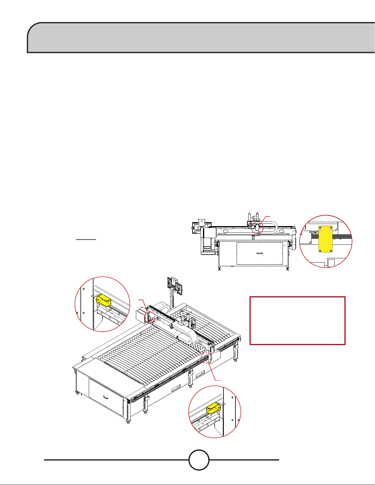
Unpacking: FlexCut 200/FlexCool 35
The FlexCut 200 is liquid cooled and is supplied with the FlexCool 35. For complete instructions on the FlexCut
200 and the FlexCool 35, see their corresponding user guides - FlexCut 200 - IM10422, FlexCool 35 - IM10423
Unpacking the FlexCool 35:
The packaging of the cooler is designed to withstand
shipping abuse. If any shipping damage has occurred, contact
your certied Lincoln distributor or service center. When
unpacking the unit, avoid thrusting sharp objects through
the carton, which may damage the machine. Below is the
recommended procedure for unpacking the cooler:
1. Cut and remove banding straps around skid and carton
2. Remove carton
3. Cut and remove banding straps around skid and cooler
4. Remove cooler, literature, and other items
Save the instruction manual and service directory supplied with
the FlexCool 35 for parts orders and future maintenance service.
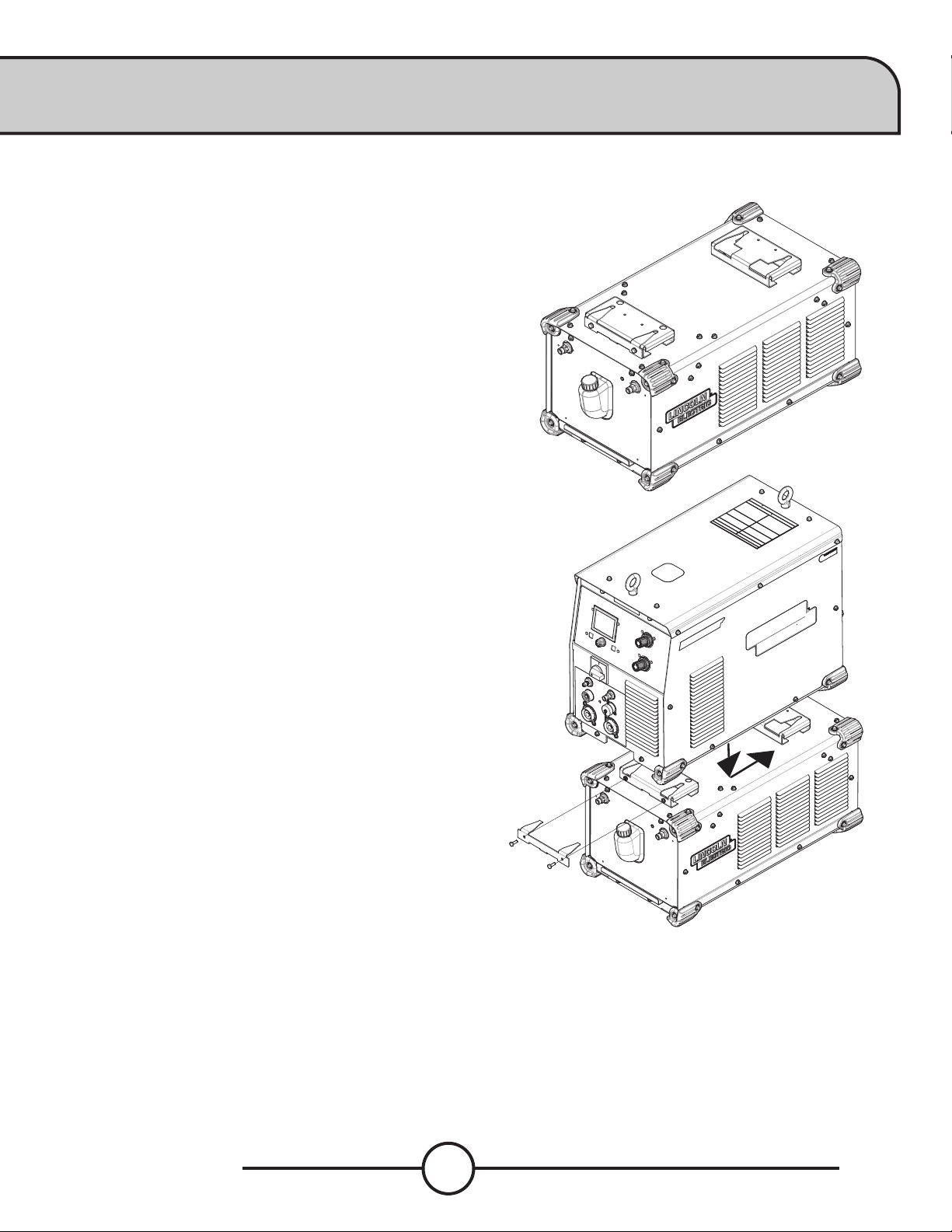
Mounting the FlexCool 35 underneath the FlexCut 200:
The FlexCool 35 can be mounted underneath the FlexCut 200
machine or by itself on a at surface. No power source should
ever be installed underneath the FlexCool 35.
Securing the FlexCut 200 to the FlexCool 35:
1. Begin by setting the FlexCool 35 on a hard at surface.
2. Remove the two 7/16" bolts and the locking bracket from the
front mounting bracket.
3. Lift the FlexCut 200 and place it on top and slightly
forward of the FlexCool 35.
4. Carefully guide the FlexCut 200 so that the quick lock feet on
the bottom of the power source slide into the channels of
the mounting brackets on top of the FlexCool 35. Be sure all 4
feet are within the channels.
5. Slide the FlexCut 200 all the way back so that it is sitting
exactly overtop of the FlexCool 35. The feet should be all the
way at the back of the channels.
6. Replace the locking bracket into the front mounting bracket
of the FlexCool 35. Torque both 7/16" bolts to 50 in-lbs.
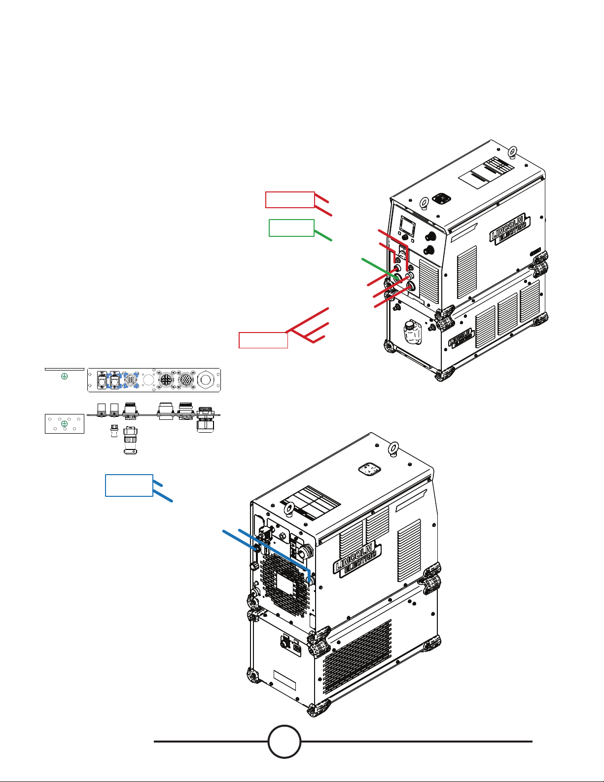
1.5 gallons of coolant are preloaded into the machine at the facility for live re testing.
Pour 0.75 gallons (2.84 liters) of coolant into the coolant reservoir ll hole through a funnel.
Use the coolant purge command in the machine UI menus to help prime the system.
While priming, add additional coolant to keep the reservoir full. The cooler is "FULL" when the coolant lies just
below the coolant reservoir opening.
Be certain to replace the reservoir ll cap when the reservoir is full. Operation of the FlexCool 35 without the
reservoir cap can cause unnecessary contamination and could be hazardous to others. See the FlexCool 35
manual for complete instructions and safety precautions.
Filling the Coolant Reservoir:
USE ONLY LINCOLN ELECTRIC TORCH COOLANT - BK500695

ix User Guide
Connections between the FlexCut 200 and FlexCool 35:
1. Connect the 115v from the FlexCool 35 to the 115v connection
on the back of the FlexCut 200.
2. Connect the ARCLINK cable from the FlexCut 200 to the
FlexCool 35.
3. The two coolant supply lines from the FLEXSTART box will
be coming out the cable carrier. Attach the supply lines to
the FlexCool 35.
4. On the gantry by the FLEXSTART box, remove the zip tie
and connect the two hoses and ARCLINK barrel connector to
the FLEXSTART.
The FlexCut 200 does not come with an SO cord
installed for the main power connection. Use
a three-phase supply line. A 1.75 inch (45
mm) diameter access hold for the input supply is
located on the case back.
Connect L1, L2, L3 and ground per connection
diagrams and National Electric Code.
To access the input power connection block,
remove the seven screws and the left case side
of the machine as shown.
COOLANT SUPPLY
COOLANT RETURN
TO
FLEXSTART
Input Cord Strain Relief:
Route input cord through
relief and twist nut to tighten.
Ground Connection:
Connect Ground Lead per local
and national electrical codes
Power Connection Block:
Connect each phase of a three
phase connector here
115 V
AC**
ARC LINK
ARCLINK
COOLANT RETURN
COOLANT SUPPLY
GROUND
FROM
POWER
SOURCE
FROM
COOLER
TO
STAR
GROUND
FLEXSTART boxes are mounted to the gantry on the 5100.
Hoses and cables are run into the cable carrier.

Torchmate 5100 x
Connections between the FlexCut 200 and FlexCool 35:
1. From the cable carrier, connect the PLASMA GAS and SHIELD GAS to the FlexCut 200.
2. Attach the Plasma connections from the cable carrier to the nozzle, ARCLINK, and electrode.
3. Connect the WORK to the STAR GROUND BLOCK on the machine.
4. Connect the CNC interface cable to the BULKHEAD P1 and P2.
5. Connect the ETHERNET connector to the back of the FlexCut 200. Attach the other end to the ETH1 port to the Fiber
Optic box. Attach the ber optic and power cable to the converter box.
For full wiring instructions, see the corresponding manuals for the FlexCut 200 and FlexCool 35.
NOZZLE
ARC LINK
ELECTRODE
WORK
PLASMA GAS
SHIELD GAS
FROM
CABLE CARRIER
FROM
CABLE CARRIER
TO
STAR GROUND
Star Ground
Star Ground
P1
PLASMA
INTERFACE
P2
RESERVED
P3
CAN
INTERFACE
P4
AUXILARY
I/O
POWE R
ENTRY
ETH 1
FLEXNET
ETH 0
EXT. NETW ORK
CNC INTERFACE
ETHERNET
TO
5100 BULKHEAD

xi User Guide
Unpacking: FineLine 170HD / 300HD
The 5100 with the FineLine HD systems will be professionally installed at a customers location. Due to
the weight of the power supplies, 700lbs+, there are requiremnts that need to be met when handling the
equipment. For complete instructions, see the FineLine Operators Manual.
The FineLine 170HD and Fineline 300HD should be lifted by a forklift, pallet jack or crane. In order to prevent
damaging the Power Supply when lifting with a forklift or pallet jack, the forks should be of adequate length to
protrude on the far side of the Power Supply.
If lifting by lifting eye, ensure the following:
• Material handling equipment must comply with local
and national laws and regulations. The personnel
involved in the move must be properly trained and
qualied to use such equipment.
• All power supply covers must be securely installed.
• Lift slowly -not more than 8 in. (203.2mm) high- to
ensure even weight distribution.
• Move slowly to prevent uncontrollable acceleration/
deceleration.
Unboxing and Leveling
1. Place the FineLine Power Supply on a at and level
surface.
2. Remove the wooden crate and plastic bag
surrounding the Power Supply.
3. Remove the rear input cover to nd the operator’s
manual and accessories.
4. Remove the eight screws and washers and four
mounting plates between power supply and skid.
5. Lift the machine o of the skid.
6. With the machine properly lifted and secured,
carefully thread each leveling foot in place while
keeping the jam nut between the foot and the base.
Be careful not to cross thread the feet and be sure
the threads are fully engaged with the base. Roughly
adjust all four feet to the same desired height.
7. Set the machine on the oor, adjust the feet to level
the machine, and then tighten the jam nut against
the base to lock their position.
Lifting Eye
Tighten to Lock Position
Height Adjustment

Torchmate 5100 xii
Technical Support | On-Site Service
Lincoln Electric Cutting Systems provides a number of technical support opportunities with the purchase of
your new Torchmate 5100 CNC cutting machine. The following is a brief outline of available options. Onsite
visits are available at an additional cost, call 775-673-2200 for additional information.
• Phone Support:
Phone support is available Monday – Friday 7:00am-4:00pm Pacic Time.
Lincoln Electric will make every eort to handle phone calls in a timely manner, but due
to the nature of machine diagnoses and the varied capabilities of machine operators,
we cannot guarantee hold wait times for phone-in technical support. Technical support
includes machine assembly, troubleshooting, conguration, and quality-related issues.
Operational training is not included in phone technical support.
• E-mail:
24 hours Monday-Friday.
• Torchmate Training:
Lincoln Electric provides a number of training opportunities at our Reno, Nevada campus. Please
call (775)-673-2200 for details or visit http://torchmate.com/training
• Torchmate Academy:
Torchmate Academy is a high-denition, detailed video walkthrough covering every
aspect of your Torchmate table including setup, operation, detailed Torchmate CAD
videos, and maintenance. Call (775) 673-2200 or visit the website to learn more.
http://torchmate.com/academy
• Torchmate YouTube Channel:
Lincoln Electric provides a wide selection of how to tutorials on our YouTube page.
https://www.youtube.com/user/torchmatedotcom
• Torchmate Store:
A variety of consumables, parts, and accessories can easily be purchased online through
the Torchmate store. Visit https://www.torchmatestore.com/ to learn more.

1User Guide
Safety Information
Torchmate and Lincoln Electric Cutting Systems equipment is designed and built with safety in mind. However, your overall safety
can be increased by proper installation and thoughtful operation.
WARNING: DO NOT INSTALL, OPERATE, OR REPAIR THIS EQUIPMENT WITHOUT READING THE SAFETY WARNINGS CONTAINED
THROUGHOUT THIS MANUAL.
Please Note:
PROTECT YOURSELF AND OTHERS FROM POSSIBLE SERIOUS INJURY OR DEATH
KEEP CHILDREN AWAY
IF YOU WEAR A PACEMAKER, YOU SHOULD CONSULT WITH YOUR DOCTOR BEFORE OPERATING
• Read and understand the following safety highlights. For additional safety information, it is strongly recommended that you obtain a
copy of “Safety in Welding & Cutting - ANSI Standard Z49.1” from the American Welding Society, P.O. Box 351040, Miami, Florida 33135
(free download available at https://www.aws.org/standards/page/ansi-z491), or purchase CSA Standard “Safety in Welding, Cutting and
Allied Processes,” CSA Standard W117.2 (https://www.cwbgroup.org/store/codes-standards/csa-w1172-2019-safety-welding-cutting-
and-allied-processes).
BE SURE THAT ALL INSTALLATION, OPERATION, MAINTENANCE, AND REPAIR PROCEDURES ARE PERFORMED ONLYBY
QUALIFIED INDIVIDUALS
ELECTRIC SHOCK CAN KILL:
• The electrode and work (or ground) circuits are electrically “hot” when the power source is on. Do not touch
these “hot” parts under any circumstances. Use suitable clothing, including gloves made from durable, ame
resistant material.
• Disconnect the power source before performing any service or repairs. When the power source is operating,
voltages in excess of 250 volts are produced. This creates the potential for serious electrical shock - possibly
even fatal.
• Insulate yourself from work and ground using dry insulation. Wear dry gloves and clothing in good
condition. Take extra care when the workplace is moist or damp.
• Always be sure the work cable makes a good electrical connection with the metal being cut, or gouged. The
connection should be as close as possible to the area being cut or gouged.
• Ground the work or metal to be cut or gouged to a good electrical (earth) ground.
• Maintain the plasma torch, cable and work clamp in good, safe operating condition. Repair or replace all
worn or damaged parts. Replace damaged insulation.
• Never dip the torch in water for cooling or plasma cut or gouge in or under water.
• When working above oor level, protect yourself from a fall should you get a shock.
• Operate the pilot arc with caution. The pilot arc is capable of burning the operator, others or even piercing
safety clothing.
FOR ELECTRONICALLY POWERED EQUIPMENT:
• Install equipment in accordance with the U.S. National Electrical Code, all local codes and the
manufacturer’s recommendations.
• Ground the equipment in accordance with the U.S. National Electrical Code, all local codes and the
manufacturer’s recommendations.
• Turn o input power using the disconnect switch at the fuse box before working on the equipment and
comply with lock out/tag out procedures.

Torchmate 5100 2
FUMES AND GASES can be dangerous:
Plasma cutting or gouging may produce fumes and gases hazardous to health. Avoid breathing these fumes
and gases. When cutting or gouging, keep your head out of the fumes. Use adequate ventilation and/or
exhaust at the arc to keep fumes and gases away from the breathing zone.
Use an air-supplied respirator if ventilation is not adequate to remove all fumes and gases.
When plasma cutting or gouging on lead or cadmium plated steel and other metals or coatings which
produce highly toxic fumes, keep exposure as low as possible and within applicable OSHA PEL and ACGIH TLV
limits using local exhaust or mechanical ventilation. In conned spaces or in some circumstances, outdoors, a
respirator may be required.
Additional ventilation is required when cutting (zinc) galvanized steel or materials containing or coated with
any of the following:
The operation of plasma cutting or gouging fume control equipment is aected by various factors, including
proper use and positioning of the equipment, maintenance of the equipment, and the specic procedure and
application involved. Worker exposure levels must be checked upon installation and periodically thereafter
to be certain levels are within applicable OSHA PEL and ACGIH TLV limits. For information on how to test for
fumes and gases in your work place, refer to the publications section of this manual.
Do not use plasma cutting or gouging equipment in locations near chlorinated hydrocarbon vapors coming
from degreasing, cleaning, or spraying operations. The heat and rays of the arc can react with solvent vapors
to form phosgene, a highly toxic gas, and other irritating products. Remove all sources of these vapors.
Gases used for plasma cutting and gouging can displace air and cause injury or death. Always use enough
ventilation, especially in conned areas, to ensure breathing air is safe. Use an air-supplied respirator if
ventilation is not adequate to remove all fumes and gases.
Read and understand the manufacturer’s instructions for this equipment and follow your employer’s safety
practices.
This product, when used for cutting, produces fumes or gases which contain chemicals known to the State of
California to cause birth defects and/or cancer.
Some dust created by routing, sawing, grinding, drilling, and other construction activities contains chemicals
known to cause cancer, birth defects or other reproductive harm. Avoid prolonged contact with this dust.
Wear protective clothing and wash exposed areas with soap and water. Allowing dust to get into your mouth,
eyes, or lay on the skin may promote absorption of harmful chemicals.
Some examples of these chemicals are:
Lead and/or cadmium from lead or cadmium-based paint.
Crystalline silica from bricks and cement and other masonry products.
Arsenic and chromium from chemically-treated lumber (CCA).
Your risk from these exposures varies, depending on factors that include: how often you do this type of work,
the duration of the work, the metal alloy(s) being worked and the composition, and the number and types of
other operations taking place in the work area. To reduce your exposure to these chemicals; work in a well
ventilated area, and work with approved safety equipment, such as respiratory protection approved for the
contaminants present and their airborne concentrations.
Antimony Beryllium Cobalt Manganese Selenium
Arsenic Cadmium Copper Mercury Silver
Barium Chromium Lead Nickel Vanadium

3User Guide
Cutting ame and sparks can cause FIRE OR EXPLOSION:
• Fire and explosion can be caused by hot slag, sparks, oxygen fueled cutting ame, or the plasma arc.
• Have a re extinguisher readily available. Provide a re watch when working in an area where re hazards
may exist.
• When not cutting or gouging, make certain no part of the electrode circuit is touching the work or ground.
Accidental contact can cause overheating and create a re hazard.
• Be sure there are no combustible or ammable materials in the workplace. Any material that cannot be
removed must be protected.
• Sparks and hot materials from cutting or gouging can easily go through small cracks and openings to
adjacent areas.
• Avoid cutting or gouging near hydraulic lines.
• Do not cut or gouge tanks, drums, or containers until the proper steps have been taken to ensure
that ammable and/or toxic vapors from substances inside have been completely removed. They can
cause an explosion even though they have been “cleaned.” For information purchase “Recommended
Safe Practices for the Preparation for Welding and Cutting of Containers and Piping That Have Held
Hazardous Substances”, AWS F4.1 from the American Welding Society (https://pubs.aws.org/p/232/f411999-
recommended-safe-practices-for-the-preparation-for-welding-and-cutting-of-containers-and-piping-
historical).
• Vent hollow castings or containers before heating, cutting, or gouging. They may explode.
• Do not add fuel to engine-driven equipment near an area where plasma cutting or gouging is being done.
• Connect the work cable to the work as close to the cutting or gouging area as practical. Work cables
connected to the building framework or other locations away from the cutting or gouging area increase the
possibility of the current passing through lifting chains, crane cablesm, or other alternate circuits. This can
create re hazards or overheat lifting chains or cables until they fail.
• Hydrogen gas may be formed and trapped under aluminum work pieces when they are cut underwater or
while using a water table. DO NOT cut aluminum alloys underwater or on a water table unless the hydrogen
gas can be eliminated or dissipated. Trapped hydrogen gas that is ignited will cause an explosion.
• Read and follow NFPA 51B “ Standard for Fire Prevention During Welding, Cutting and Other Hot Work,”
available from NFPA, 1 Batterymarch Park, PO box 9101, Quincy, Ma 022690-9101.
CYLINDER may EXPLODE if damaged:
• Use only compressed gas cylinders containing the correct gas for the process used and properly operating
regulators designed for the gas and pressure used. All hoses, ttings, etc. should be suitable for the
application and maintained in good condition.
• Always keep cylinders in an upright position, securely chained to an undercarriage or xed support.
• Cylinders must be located away from areas where they may be struck or subjected to physical damage.
• They must be a safe distance from plasma cutting or gouging, arc welding operations and any other source
of heat, sparks, or ame.
• Never allow any part of the electrode, torch, or any other electrically “hot” parts to touch a cylinder.
• Keep your head and face away from the cylinder valve outlet when opening the cylinder valve.
• Valve protection caps should always be in place and hand tight except when the cylinder is in use or
connected for use.
Read and follow the instructions on compressed gas cylinders, associated equipment, and CGA publication P-1,
“Standard for Safe Handling of Compressed Gases in Cylinders,”available from the Compressed Gas Association,
1235 Jeerson Davis Highway, Arlington, VA 22202. (https://portal.cganet.com/Publication/Details.
aspx?id=P-1).
AIR LINES UNDER PRESSURE:
• Some tools use compressed air or gas. Flexible tubing (lines) bring the pressurized air and gas to the machine.
Inspect all lines prior to machine operation. Damaged lines should be replaced prior to operation.
• Hot sparks, ying debris, or wear can melt, burn, or puncture these lines and cause damage to the operator.
• Route air and gas lines to keep away from trac and from underfoot.

Torchmate 5100 4
For more information on electromagnetic interference please visit:
http://torchmate.com/white-papers/EMI-Reduction
HOT MATERIAL:
• Plasma cutting uses an electric arc that can reach temperatures of 45,000°F (25,ooo°C). Oxygen-fuel cut-
ting ames can reach up to 6330°F (3500°C). Any parts and scrap will be hot after cutting.
• Use proper tools and wear heat-sheilded protective gloves in good condition when handling recently cut
material.
• Allow proper cooling time prior to parts being handled.
ELECTRIC AND MAGNETIC FIELDS may be dangerous:
• Electric current owing through any conductor causes localized Electric and Magnetic Fields (EMFs). Cut-
ting or gouging current creates EMFs around torch cables and cutting machines.
• EMFs may interfere with some pacemakers and other medical implant devices, so operators who have a
pacemaker should consult their physician before cutting or gouging.
• All operators should use the following procedures in order to minimize exposure to EMF elds from the
cutting or gouging circuit:
• Route the torch and work cables together and secure them with tape whenever possible.
• Never coil the torch cable around your body.
• Do not place your body between the torch and work cables. If the torch cable is on your right side,
the work cable should also be on your right side.
• Connect the work cable to the workpiece as close as possible to the area being cut or gouged.
• Do not work next to cutting power source.
ARC RAYS CAN BURN:
• Plasma Arc Rays can injure your eyes and burn your skin. The plasma arc process produces very bright
ultraviolet and infrared rays, which will damage your eyes and burn your skin if you are not properly
protected.
• Use safety glasses and a shield with the proper lter and cover plates to protect your eyes from sparks
and the rays of the arc when performing or observing plasma arc cutting or gouging. Glasses, head-shield,
and lter lens should conform to ANSI Z87. I standards.
• Use suitable clothing including gloves made from durable, ame-resistant material to protect your skin
and that of your helpers from the arc rays.
• Protect other nearby personnel with suitable non-ammable screening and/or warn them not to watch
the arc nor expose themselves to the arc rays or to hot spatter or metal.
PLASMA ARC can cause serious injury or death:
• Keep your body away from the nozzle and plasma arc.
• Operate the pilot arc with caution. The pilot arc is capable of burning the operator, others, or even
piercing safety clothing.
Arc Current Minimum
Shade No.
Suggested
Shade No.
Less than 20A 4 4
20A-40A 5 5
40A-60A 6 6
60A-300A 8 9
300A-400A 9 12
400A-800A 10 14

5User Guide
Laser Usage:
• This product contains a diode laser. Make sure to follow all safety precautions when operating.
• DO NOT look into the direct or reected beam. This can cause eye injury up to 110 ft. (34 m) away.
• NEVER point any laser towards aircraft or vehicles; it is unsafe and illegal. The laser can cause visual
interference with pilots and drivers, and interferes with vision up to 2,400 ft (730 m) away. The laser can
be a distraction up to 4.5 miles (7.3 km) away.
• Class 3R lasers are safe when handled carefully. DO NOT look into the beam.
• Wear appropriate eye protection when working on the installation of the laser diode.
HEAVY PARTS:
• Parts of CNC machines and raw materials can be heavy. To avoid injury, get someone to help you, or use a
mechanical lifter in the event material needs to be lifted or moved. When using a mechanical lifter, follow
all the manufacturer’s safety guidelines.
NOISE:
• Long exposure to noise can lead to hearing damage or loss. CNC operations, plasma arc cutting, plate
marking can create noise levels that exceed safe limits. Use appropriate ear protection when operating
the system
• Protect the operator and others around the system by using appropriate ear protection suited for the
work environment and decible rating of the facility.
• Recommended to test the noise levels (decibles) during operation to validate excess of safe levels.
FLYING DEBRIS:
• Metal cutting and marking operations create waste that can fragment and y. Make sure you and
everyone close to the CNC machine during operations has proper eye protection.
PINCH AND CRUSH POINTS:
• Pinch and crush points are those normally moving parts of machinery, like CNC machines, that can pinch,
capture, crush, or sever parts of the body. Be aware of hazardous pinch and crush points.
• Never repair or adjust the machine without the controls on lock out/tag out.
• When the end of a CNC machine’s travel creates a “hard stop,” it creates a crush point. Keep ngers and
hands away from this.
• Do not stack or store any additional items on or in contact with the CNC machine, as this can create pinch
or crush points, and a falling hazard.
MECHANICAL DRIVES:
• High-speed mechanical drives made of gears, belts, and/or drive screws are used by CNC machines. Keep
clear of them during operation.
• Do not attempt to service, adjust, or otherwise touch these components without rst ensuring that the
machine is on lock out/tag out.
• Secure any loose clothing and cables to prevent entanglement.
AUTOMATIC OPERATION:
• Any computer numerical control (CNC) machine may begin to operate automatically without warning.
Only a trained individual familiar with the software, machine, and computer system should operate this
equipment.
• All untrained persons should not work on or near a CNC machine.
• Keep the immediate area around the CNC machine clear of materials that may cause interference. Keep
area clear of bystanders.
• Do not leave the CNC machine unattended while power is on to the computer, controller, or plasma power
source of the system.

Torchmate 5100 6
PUBLICATIONS
Refer to the most recent vesrions of the following standards for more information:
• OSHA, SAFETY AND HEALTH STANDARDS, 29CFR 1910, obtainable from the Superintendent of Documents,
U.S. Government Printing Office, Washington, D.C.
• ANSI Standard Z49.1, SAFETY IN WELDING AND CUTTING, obtainable from the American Welding Society,
8669 NW 36 Street, #130; Miami, Florida 33166-6672
• NIOSH, SAFETY AND HEALTH IN ARC WELDING AND GAS WELDING AND CUTTING, obtainable from the
Superintendent of Documents, U.S. Government Printing Office, Washington, D.C. 20402
• ANSI Standard Z87.1, SAFE PRACTICES FOR OCCUPATION AND EDUCATIONAL EYE AND FACE PROTECTION,
obtainable from American National Standards Institute, 1430 Broadway, New York, NY 10018
• ANSI Standard Z49.2, FIRE PREVENTION IN THE USE OF CUTTING AND WELDING PROCESSES, obtainable
from American National Standards Institute, 1430 Broadway, New York, NY 10018
• AWS Standard A6.0, WELDING AND CUTTING CONTAINERS WHICH HAVE HELD COMBUSTIBLES, obtainable
from American Welding Society, 8669 NW 36 Street, #130; Miami, Florida 33166-6672
• NFPA Standard 51, OXYGEN-FUEL GAS SYSTEMS FOR WELDING, CUTTING AND ALLIED PROCESSES,
obtainable from the National Fire Protection Association, Batterymarch Park, Quincy, MA 02269
• NFPA Standard 70, NATIONAL ELECTRICAL CODE, obtainable from the National Fire Protection
Association, Batterymarch Park, Quincy, MA 02269
• NFPA Standard 51B, CUTTING AND WELDING PROCESSES, obtainable from the National Fire Protection
Association, Batterymarch Park, Quincy, MA 02269
• CGA Pamphlet P-1, SAFE HANDLING OF COMPRESSED GASES IN CYLINDERS, obtainable from the
Compressed Gas Association, 1235 Jefferson Davis Highway, Suite 501, Arlington, VA 22202
• CSA Standard W117.2, CODE FOR SAFETY IN WELDING AND CUTTING, obtainable from the Canadian
Standards Association, Standards Sales, 178 Rexdale Boulevard, Rexdale, Ontario, Canada M9W 1R3
• NWSA booklet, WELDING SAFETY BIBLIOGRAPHY obtainable from the National Welding Supply
Association, 1900 Arch Street, Philadelphia, PA 19103
• ANSI Standard Z88.2, PRACTICE FOR RESPIRATORY PROTECTION, obtainable from American National
Standards Institute, 1430 Broadway, New York, NY 10018

7User Guide
Input Power
• 120V / 1Ph / 15A / 60Hz (table and computer)
• 380-600V / 3Ph / 50-60Hz (Plasma Power Supply specic)
Machine Size
• 60˝ x 120” (1524mm x 3048mm) Cutting Area
• 113.5˝ x 167” (2895.6mm x 4241.8mm) Footprint
Traverse Speed
• 1,500 ipm (0.635 mps)
Cut Speed
• Up to 450 ipm
Plate Capacity
• Holds Up To 4” (102mm) 5’x10’ (1524mm x 3048mm) Mild Steel
Weight
• 4400 lbs (1995.8 kg) - Water Table
• 5200 lbs (2358.7 kg) - Downdraft Table
Operating Temperature
• 32-104° Fahrenheit (0-40° Celsius)
Motors
• Servo Motors Fitted with Rotary Glass Encoders
Drive System
• Helical Gear Rack and Hardened Pinion with Lubrication System
Linear Guidance
• Prole Linear Rail
Acceleration Rate
• 0.08g (0.06g Bevel)
Deceleration Rate
• 0.08g (0.06g Bevel)
Input Pneumatics
• Minimum 115PSI Supply Pressure
• Volume - 7 SCFM (420 SCFH) @ 90PSI
Height Control
• Ohmic Sensing
• Automatic Torch Height Control
• 6.75” Z-axis Travel
Bevel Capabilities (optional FC125/FC200)
• +/-45° Rotation (dependent on material thickness and power supply
conguration)
Software
• Easy-To-Use Lincoln Electric User Interface
• CAM with Irregular Part Nesting
• Popular Shape Library
Fume Extraction (Optional Accessory)
• 61,801 ft3/hr or 1,750 m3/hr minimum
• Automatic Filter Cleaning, Pressure Controlled
Downdraft Conguration
• Multiple Zones Controlled By Motion Controller
Safety
• Dual-Channel Safety System Supporting Emergency Stop Switch
• Safety System Extended To External Peripherals
• External Drive Power On Switch
Warranty
• *1 Year Warranty
TORCHMATE 5100 CNC
PLASMA SYSTEMS FlexCut 125 FlexCut 200 FineLine 170HD FineLine 300HD
PRODUCTION CUTTING CAPACITY
Mild Steel 1” (25mm) 1.25” (32mm) 1.25” (32mm) 1.75” (45mm)
Stainless Steel 3/4”(20mm) 3/4”(20mm) 1” (25mm) 1.25” (32mm)
Aluminum 5/8”(16mm) 3/4”(20mm) 1” (25mm) 1” (25mm)
CUTTING SPEED @ RATED
OUTPUT CURRENT
1/4” MS 210 ipm @125A 200 ipm @200A 230 ipm @ 170A 230 ipm @ 200A
1/2” MS 88 ipm @125A 110 ipm @200A 120 ipm @ 170A 135 ipm @ 275A
1” MS 32 ipm @125A 40 ipm @200A 50 ipm @ 170A 70 ipm @ 300A
PROCESS AMPS 20A - 125A 15A - 200A 10A - 170A 30A - 300A
CUTTING GAS
Mild Steel Air / Air Air / Air Oxygen / Air Oxygen / Air Oxygen / Oxygen Oxygen / Air Oxygen / Oxygen
Stainless Steel Air / Air Nitrogen Air / Air Nitrogen Air / Air Air / Nitrogen H17/Nitrogen Air / Air Air / Nitrogen H17/Nitrogen
Aluminum Air / Air Air / Air Air / Nitrogen Air / Nitrogen
INPUT VOLTAGE 380/400/415V3Ph50/60Hz 380/460/575V3Ph50/60Hz 380-415/460/575V/3Ph/50/60Hz 380-415/460/575V/3Ph/50/60Hz
460V 3Ph 50/60Hz 400V3Ph 50Hz (CE) 380-415/3Ph/50/60Hz (CE) 380-415/3Ph/50/60Hz (CE)
575V 3Ph 50/60Hz
Table Specications

Torchmate 5100 8
Site Preparation
When installing a Lincoln Electric CNC Cutting System in your shop, there are many factors that will inuence the
potential productivity, ease of use of the machine and the safety of the operator. The main factors to prepare for
include: the physical placement of the machine, the availability of power, an EMI ground, compressed air, other
input gases, and ventilation.
Please Note:
When preparing to install the Lincoln Electric CNC Cutting System, provide sucient space. Three feet of work
space (914 mm) should be obstacle free around the machine.
• Side load material opposite the cable carrier only! Utilize the back of the machine to park the gantry while loading
material.
• A dedicated earth ground must be provided and should be installed in a manner to reduce trip hazard.
113.25”
167”
Load From
This Side
Operator
Console
MAINTAIN WORK AREA
5100
FlexCut
Plasma
(within 10’ of cable
carrier)
15’ Power Cord, NEMA 5-15P
Shop Air Supply
Earth Ground (provided by customer)
Incoming AC power
for Plasma Cutter
Shop air supply
14” Duct, Downdraft
Models Only
Other manuals for Torchmate 5100 Series
3
Table of contents
Other Lincoln Electric Industrial Equipment manuals

Lincoln Electric
Lincoln Electric AEROMIG 3D Mounting instructions

Lincoln Electric
Lincoln Electric Statiflex 6000-MS User manual

Lincoln Electric
Lincoln Electric WELDLINE WELDRY 372N - INOX Maintenance and service guide

Lincoln Electric
Lincoln Electric Harris 240 Series User manual

Lincoln Electric
Lincoln Electric AS-XP-95240726 Instructions for use

Lincoln Electric
Lincoln Electric PRISM DOWN DRAFT User manual