Hewalex 2KSR10 User manual

- 1 -
INSTRUKCJA MONTAŻU KOLEKTORA 2KSR10.
2KSR10 COLLECTOR ASSEMBLY INSTRUCTIONS.
MONTAGEANWEISUNG DES KOLLEKTORS 2KSR10.
vb
f
Nr /
No /
Nr.
Nazwa / Name / Bezeichnung
Ilość /
Mount /
Menge
1 Panel górny / Top panel / Oberes paneel 2
2 Panel dolny / Bottom panel / Unteres Paneel 2
3 Kształtownik wzdłużny / Vertical bar /
Längsstrebe 2
4 Rura próżniowa / Vacuum tube / Vakuumrohr 20
5 Rura miedziana Ø6 x1980 / Copper tube Ø6
x1980 / Kupferrohr Ø6 x1980 20
6 Sprężyna / Spring / Feder 20
7
Nakrętka złączki zaciskowej 3/8” /
Clamp connector nut 3/8” /
Befestigungsschellen-Mutter 3/8”
20
8 Pierścieńzaciskowy / Shrink disc /
Befestigungsring 20
9 Oring silikonowy (czerwony) / Silicone O-ring
(red) / Silicon O-Ring (rot) 20
10 Łącznik / Connector / Verbindungsstűck 8
11 Wkładka / Insert / Einsatz 8
12
Śruba
M6x35
/
Screw
M6x35 /
Schraube
M6x35 8
13 Podkładka Ø6 / Washer Ø6 / Unterlage Ø6 8
14 Nakrętka M6 / Nut M6 / Mutter M6 8
15
Śruba
M8x16
/
Screw
M8x16
/
Schraube
M8x16 16
16 Podkładka Ø8 / Washer Ø8 / Unterlage Ø8 16
17 Nakrętka M8 / Nut M8 / Mutter M8 16
- 2 -
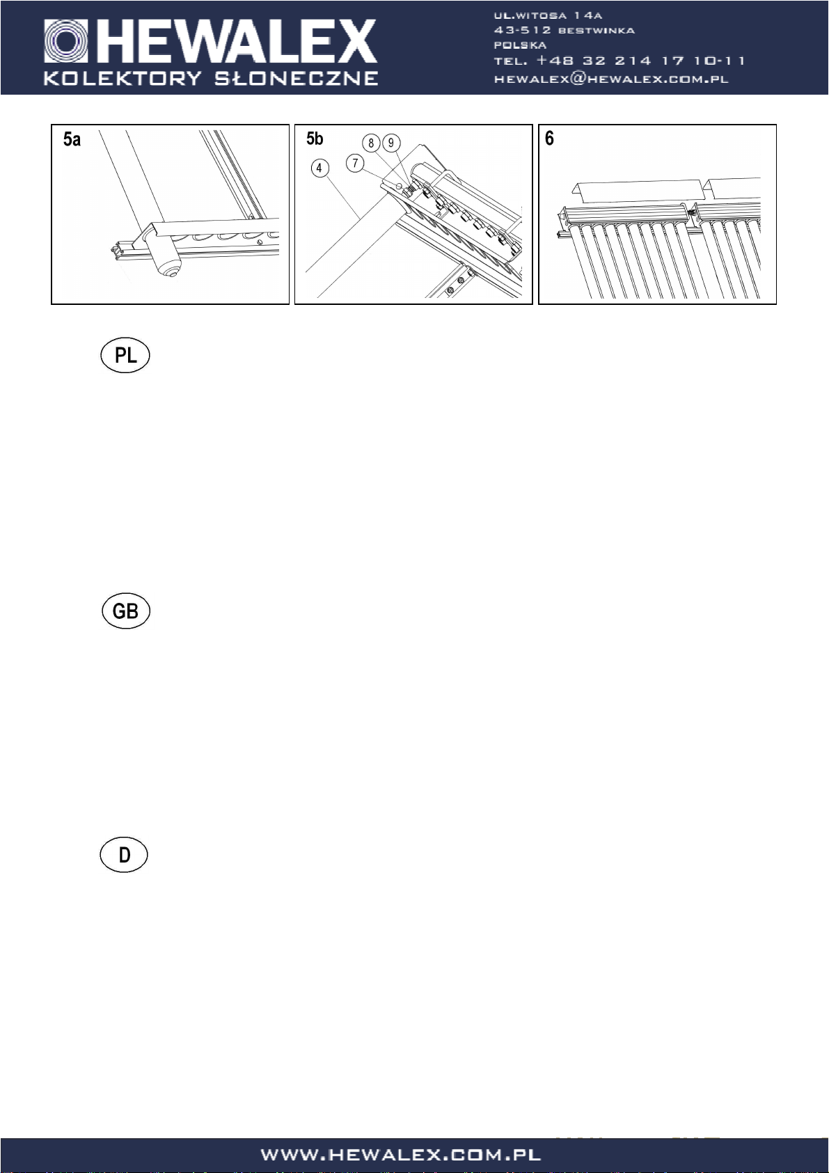
Instrukcja montażu kolektora 2KSR10.
Kolejne czynności montażu:
1. Do kształtowników wzdłużnych z otworami (3) zamocowaćłączniki (10).
2. Wsunąć po dwie wkładki (11) wraz ze śrubami (15) do kształtowników wzdłużnych (3). Śruby te połączyćz dobranymi w zamówieniu i
odpowiednio zainstalowanymi uchwytami (konstrukcją) oraz mocno dokręcić. Rozstaw kształtowników wzdłużnych (3) dla kolektorów
próżniowych powinien wynosićokoło 0,9 m.
3. Zamocowaćpanele górne (1) (rys. 3b), oraz panele dolne (2) (rys. 3c) do kształtowników wzdłużnych (3) za pomocąwkładek (11), śrub
(15), podkładek (16) i nakrętek (17).
4. Zdjąć pokrywy paneli górnych (1).
5. Zainstalowaćrury próżniowe (4).
6. Po sprawdzeniu szczelności instalacji i założeniu czujnika temperatury, nałożyćpokrywy paneli górnych (1).
2KSR10 collector assembly instructions.
Steps of the assembly:
1. Attach the connectors (10) to the vertical bars with openings (3).
2. Slide two inserts (11) together with screws (15) into the vertical bars (3). Connect the screws with the correctly installed holder (or structure)
which you individually picked for your collector and tighten the nuts. The spacing between the vertical bars (3) for vacuum collectors should
be about 0.9 m.
3. Attach the top panels (1) (fig. 3b), and the bottom panels (2) (fig. 3c) to the vertical bars (3) with the use of inserts (11), screws (15),
washers (16) and nuts (17).
4. Remove the covers from the top panels (1).
5. Install the vacuum tubes (4).
6. After checking the installation’s air-tightness and installing the temperature sensor, put the covers of the top panels (1) back on.
Montageanweisung des Kollektors 2KSR10.
Montageschritte:
1. Verbindungsstücke (10) an die Längsprofile mit Öffnungen (3) befestigen.
2. Je zwei Zwischenstücke (11) samt Schrauben (15) in die Längsprofile (3) einschieben. Diese Schrauben mit den in der Bestellung gewählten
und entsprechend eingebauten Halterungen (Konstruktion) verbinden und fest anziehen. Der Abstand der Längsprofile (3) für die
Vakuumkollektoren soll ca. 0,9 m betragen.
3. Die oberen (1) (Abb. 3b), und unteren (2) Paneele (Abb. 3c) an die Längsprofile (3) mittels Zwischenstücke (11), Schrauben (15), Scheiben
(16) und Muttern (17) befestigen.
4. Die Hauben der oberen Paneelen (1) abnehmen.
5. Vakuumrohre (4) einbauen.
6. Nach der Dichtheitsprüfung der Anlage und Einbau des Temperaturfühlers die Hauben der oberen Paneele (1) aufsetzen.
Table of contents
Other Hewalex Solar Panel manuals


Popular Solar Panel manuals by other brands


CSUN
CSUN CSUN295-72M installation guide

EGING PV
EGING PV EG-P72-HC-DG Series General installation manual

Trina Solar
Trina Solar 210 Vertex Series user manual

Sunrise
Sunrise Aquaman SR-54MNHLPro Installation and operation manual

PROMETHEUS SOLAR
PROMETHEUS SOLAR Plug & Play Solar Kits GT user manual
-E6 Series installation manual")
LG
LG LG N1C(W)-E6 Series installation manual

Camec
Camec 2 Series quick start guide

Hali-Brite
Hali-Brite SPS Series Installation and maintenance manual

Snapper
Snapper 1691245 Operator's manual

HomePluss
HomePluss 200210002 manual

INISOL
INISOL NEO 2.1 Installation and service manual

boviet SOLAR
boviet SOLAR Vega BVM7612M H-HC-BFDG Series Installation and maintenance manual