HG2 REAR RUNNER 2013 Ford F-Series User manual

REAR
2019 © Copyright HG2 Emergency Lighting. All Rights Reserved | PATENT PENDING • U.S. Patents #6,612,726; #6,962,427
V01052019
HG2LIGHTING.COM/SUPPORT
INSTALL GUIDE
1
®
REAR RUNNER ®
INSTALL GUIDE
2013-2023 Ford F-Series
866.468.4569 |www.HG2LIGHTING.com | Support@HG2Lighting.com
© 2023 Copyright HG2 Emergency Lighting. All Rights Reserved.
REAR
2023 © Copyright HG2 Emergency Lighting. All Rights Reserved | PATENT PENDING • U.S. Patents #6,612,726; #6,962,427
V01052019
HG2LIGHTING.COM/SUPPORT
INSTALL GUIDE
2
®
The HG2 Runner® Package is an
extremely versatile emergency lighting
system designed for maximum visibility
with a minimal footprint. HG2 Runners
were developed to enhance the outline
patterns and lighting intensity.
Our patent-pending designs feature
impact polycarbonate housing and a
powder-coated extruded aluminum
mounting sleeve for stealth installation.
SAFETY FIRST!
This guide provides information for a
safe and proper installation of your HG2
read this guide in its entirety before
attempting to install or operate this
product.
prevent damage or serious injury.
The installation of this kit may require
vehicle lift. Never work on a vehicle
supported only by a jack. Observe all
warnings and procedures as outlined in
the manual or instructions provided by
vehicle lift and other necessary tools
required to install this kit.
Installer or technician should have a
good understanding of automotive
knowledge of related automotive
systems and procedures.
be taken to avoid damage/interference
to vehicle components and systems—
and wiring:
before drilling or inserting fasteners
accessible location that provides
for safe operation of the vehicle and
product controls under any driving
condition
where lifts or jacks are used to raise the
vehicle
that interferes with the deployment of
an airbag
When wiring this product:
holes drilled for wiring
brake pedal
equivalent
all chassis ground connections for
interferes with the deployment of an
airbag
The installer or technician assumes any
and all responsibility to determine proper
consideration of the safety of the vehicle
operator and passengers.
DO NOT:
blindness and/or damage to your eyes
interfere with/impede safe operation of
vehicle
lighting system during hazardous
driving conditions
solvents or other chemicals
FAILURE TO FOLLOW THESE GUIDELINES
COULD CAUSE DAMAGE TO THE PRODUCT,
VEHICLE AND/ORSERIOUS PERSONAL
INJURY OR DEATH.
NEVER WORK UNDER
THE HOOD WITHOUT THE
PROPER EQUIPMENT
IN PLACE TO HOLD
THE VEHICLE SAFELY
AND SECURELY WHILE
OPERATING/FIXING IT
!
UNDERSTANDING THE GUIDELINES
!
REAR
2023 © Copyright HG2 Emergency Lighting. All Rights Reserved | PATENT PENDING • U.S. Patents #6,612,726; #6,962,427
V01052019
HG2LIGHTING.COM/SUPPORT
INSTALL GUIDE
3
®
1 – Installation Guide and Warranty Info
1. Read the installation guide for this
product in its entirety.
review parts list.
12v power supply to ensure
components are in working order.
from vehicle battery.
5. Remove door sill panels at all
door locations.
6. Place vehicle on vehicle lift or
jack stands.
(Additional tools may be required
to complete installation)
Model:
Pre-Install Instructions:
Parts List:Required Tools
INSTALL PREPARATION & TOOLS

REAR
2023 © Copyright HG2 Emergency Lighting. All Rights Reserved | PATENT PENDING • U.S. Patents #6,612,726; #6,962,427
V01052019
HG2LIGHTING.COM/SUPPORT
INSTALL GUIDE
4
®
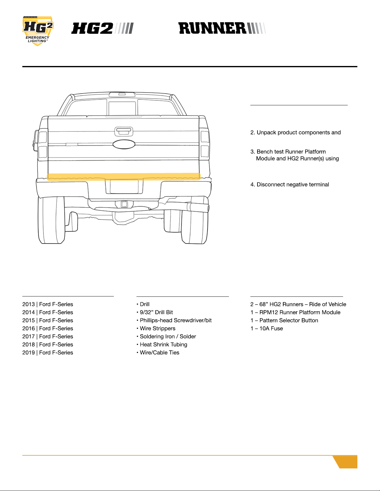
Open Tailgate door to check obstruction
of Runner to avoid the product from
getting damaged or crushed.
NOTE: Use another person to help align
Runner position while checking tailgate
door.
Step 1
Step 2
Step 3
While checking alignment, Install one
self-tapping screw down the middle of
Runner to hold it in place.
NOTE: Check once again for Runner
obstructing the tailgates pathway.
Place Runner against tailgate to
ensure correct sizing and placement
before do the install.
NOTE: Do not place Runner too high
under tailgate door.
It is highly recommended that the
installer has assistance in positioning
and holding the runner assembly during
the inspection and mounting process.
!
REAR
2023 © Copyright HG2 Emergency Lighting. All Rights Reserved | PATENT PENDING • U.S. Patents #6,612,726; #6,962,427
V01052019
HG2LIGHTING.COM/SUPPORT
INSTALL GUIDE
5
®
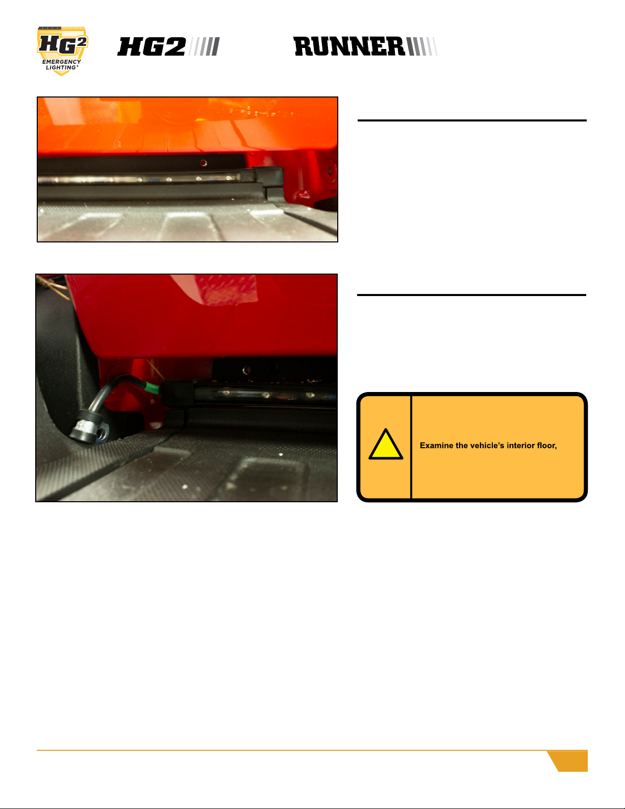
Once Runner is in place runner factory
wire down left side of tailgate to the
underside of vehicle.
NOTE: Wire from Runner will feed under
left side of vehicle.
Step 5
Inspect exterior of vehicle to ensure
mounting fasteners will not be
obstructed by, or damage, vehicle
systems such as fuel or brake lines.
under carpet and door sills to make
certain drilling of holes or insertion of
fasteners will not damage or interfere
with wiring, sensors or computers.
!
Step 4
While Runner is being held in place to
the tailgate, use self-tapping screws to
mount the remaining factory holes.
Left & Right Openings
REAR
2023 © Copyright HG2 Emergency Lighting. All Rights Reserved | PATENT PENDING • U.S. Patents #6,612,726; #6,962,427
V01052019
HG2LIGHTING.COM/SUPPORT
INSTALL GUIDE
6
®
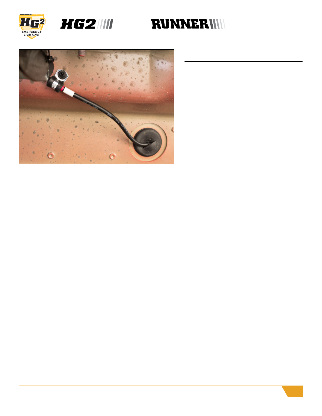
Factory grommet will be utilized in
the rear of the vehicle, located near
the rear wheel well.
With door sill and kick panel removed,
lift carpet to access factory grommet
for wire routing.
Fasten wire stress-relief
clamp(included) to underside of
vehicle in a suitable location using
self-tapping sheet metal screw.
Wiring
REAR
2023 © Copyright HG2 Emergency Lighting. All Rights Reserved | PATENT PENDING • U.S. Patents #6,612,726; #6,962,427
V01052019
HG2LIGHTING.COM/SUPPORT
INSTALL GUIDE
7
®
INSTALLATION
Preparation
1. Read the installation guide for this product in its
entirety.
using 12v power supply to ensure components are in
working order.
5. Prepare mounting location by removing interior panels
as necessary.
Mounting
operation of the vehicle.
Wiring
protected using appropriate heat shrink tubing.
BASIC OPERATION
Demo mode
again without pattern selector button depressed.
Selecting Patterns
Press pattern selector button to select a new pattern. The
selected pattern is retained even after cycling power.
Inspect exterior of vehicle to ensure
mounting fasteners will not be obstructed by, or
damage, vehicle systems such as fuel or brake
carpet and door sills to make certain drilling of
holes or insertion of fasteners will not damage or
interfere with wiring, sensors or computers.
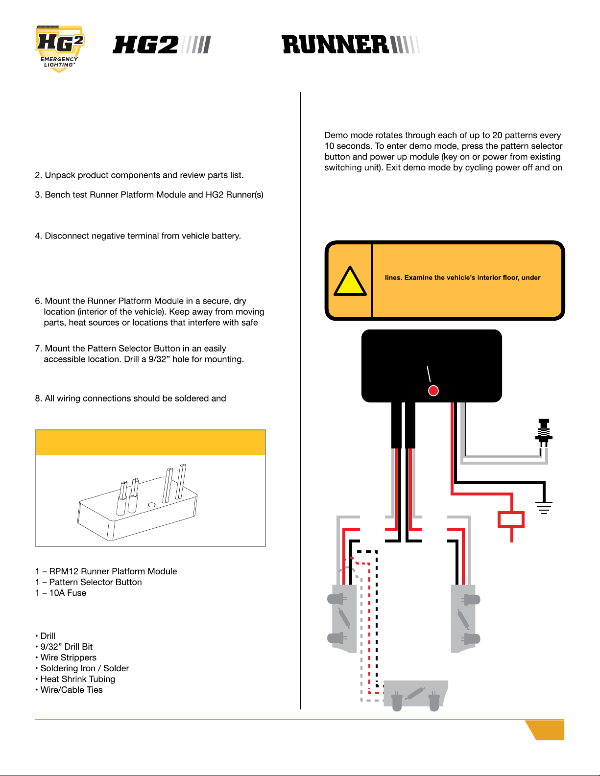
Chassis Ground
HG2 Runner HG2 Runner
To (+) 12 Volt Power Source
(Existing Switiching Module)
Rear Bumper/Tailgate Runner
(optional)
Pattern Selector Button
Power
Indicator
Black
White
Red
Black
White
Red
Black
Red
7A Fuse
Runner Platform Module [RPM12]
Parts List
1 – Installation Guide and Warranty Info Packet
Required Tools
(Additional tools may be required to complete installation)
!
2023 © Copyright HG2 Emergency Lighting. All Rights Reserved | PATENT PENDING • U.S. Patents #6,612,726; #6,962,427
HG2LIGHTING.COM/SUPPORT8
This warranty gives you certain rights and you may also have other rights
that may vary from state to state. This warranty is given only to the end-
Product Registration
days of purchase.
What Is Covered
there are no defects in the materials and workmanship of this Product.
purchase with proof of purchase.
What Is NOT Covered
you
did not purchase this Product from an authorized HG2 reseller within the
this Product has been abused or
this
Product has been transported without the proper preparation and
installed the unit.
If Your Product Defective
HG2’s representative with a copy of your dated bill of sale showing that
What HG2 Will Do
HG2 will evaluate your report of a possible defect to determine whether
with a product that performs the same functions and performs as well
as the original Product. HG2 reserves the right to supply refurbished or
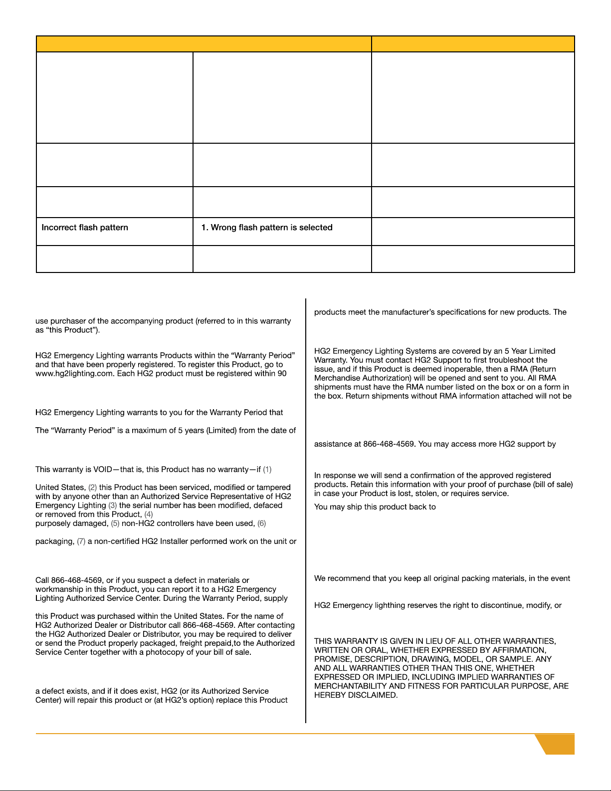
Problem
TROUBLESHOOTING
WARRANTY
HG2 Product does not illuminate 1. No power to RPM12 module
2. Power wires reversed
3. Fuse blown
4. Improper ground to chasis
1. Check wiring for loose connection;
check fuse
2. Checking wiring diagram;reverse power
wires
3. Replace fuse
4. Ensure ground wire terminates to metal
chassis ground
External fuse blows
HG2 Product illuminates regardless
of ignition switch postion
Flash patterns continually change
1. Power wires shorted
2. Incorrect fuse size
1. RPM12 Module wired to constant +12v
power source
1. RPM12 Module in “Demo Mode”
1. Check wiring connection to RPM12
Module for switched power
1. Select another pattern; see Basic
Operations: Selecting Patterns
1. Exit “Demo Mode”; see Basic Operations:
Demo Mode
1. Check power connections for damaged or
shorted wiring
2. Replace with correct fuse size
Solution
remanufactured replacement products provided that the replacement
repaired or replacement product will be returned to you at no cost.
Exchange Service
guaranteed.
HG2 Support
Toll-free customer service and technical support is available for
going to the HG2 website at: www.hg2lighting.com.
Please keep a record of this Product by completing the online registry.
Attn: Returns
HG2 Emergency Lighting
477 N. Semoran Blvd, Orlando FL, 32807
Important
that you ship this product.
upgrade any products it manufactures with design improvements without
prior notice.
This manual suits for next models
6
Table of contents
Other HG2 Automobile Accessories manuals


Popular Automobile Accessories manuals by other brands


Reer
Reer BabyView instruction manual

Prorack
Prorack K916 Fitting instructions

Prorack
Prorack K340W Fitting instructions

Big Mikes Performance Parts
Big Mikes Performance Parts STO N SHO SNS 48 Installation procedures

Graber
Graber All Star Assembly instructions/use and care manual

Vixen Horns
Vixen Horns VXH1167CX2 installation guide


