Let's Go Aero BLACK BOX Owner's manual
Other Let's Go Aero Automobile Accessories manuals
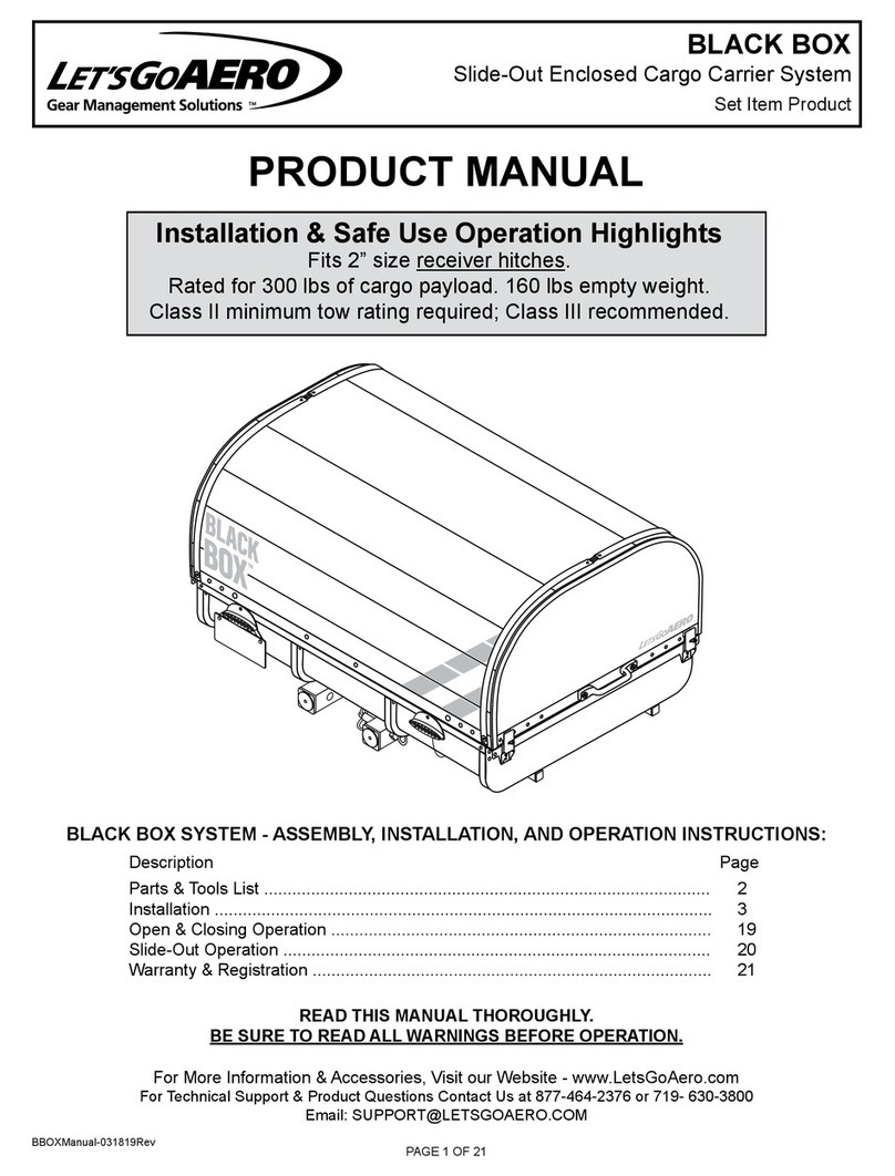
Let's Go Aero
Let's Go Aero BLACK BOX User manual
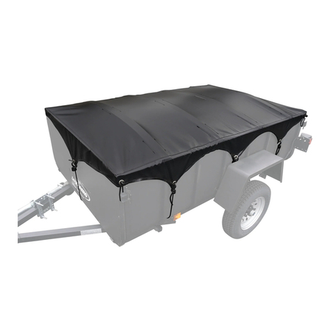
Let's Go Aero
Let's Go Aero Seal Skin Tonneau Cover Installation instructions
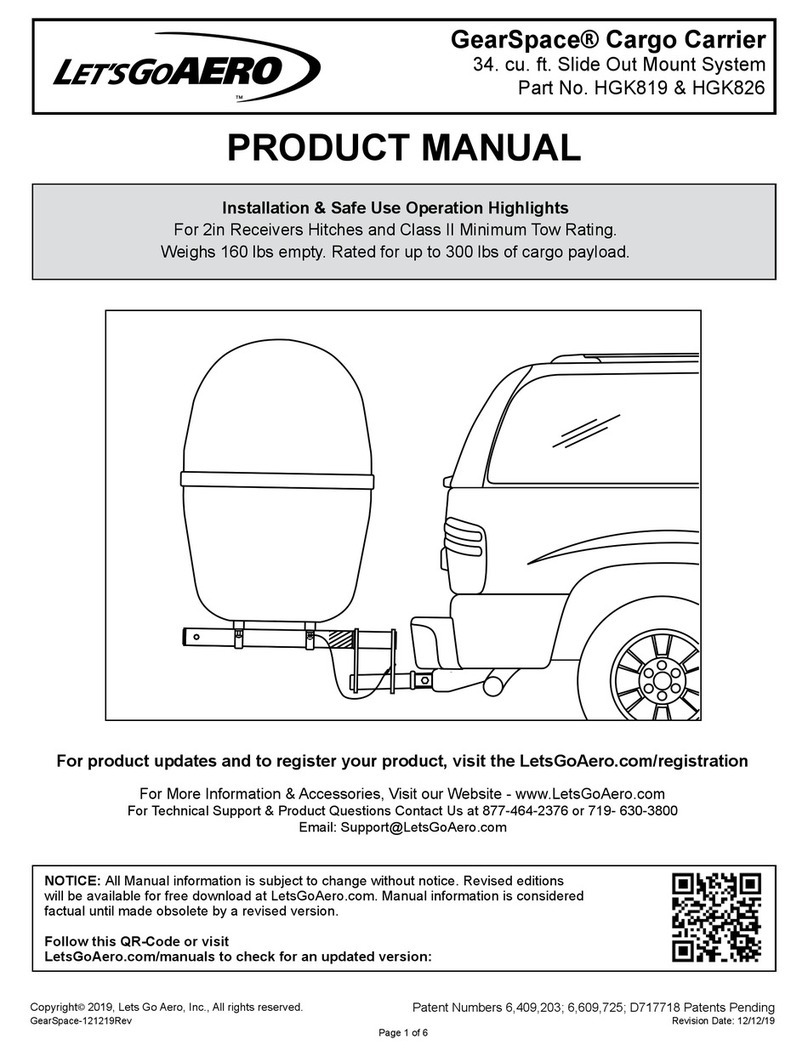
Let's Go Aero
Let's Go Aero GearSpace HGK819 User manual

Let's Go Aero
Let's Go Aero GearCage Ramp User manual
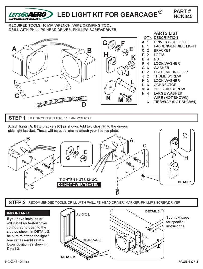
Let's Go Aero
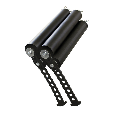
Let's Go Aero HCK345 User manual
Let's Go Aero
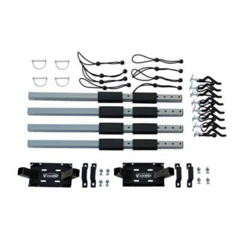
Let's Go Aero PegBoard B01588 Installation instructions
Let's Go Aero
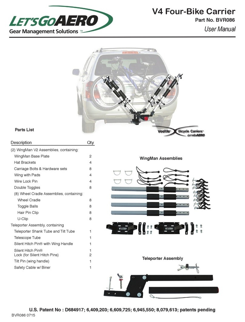
Let's Go Aero VME-V4 User manual
Let's Go Aero
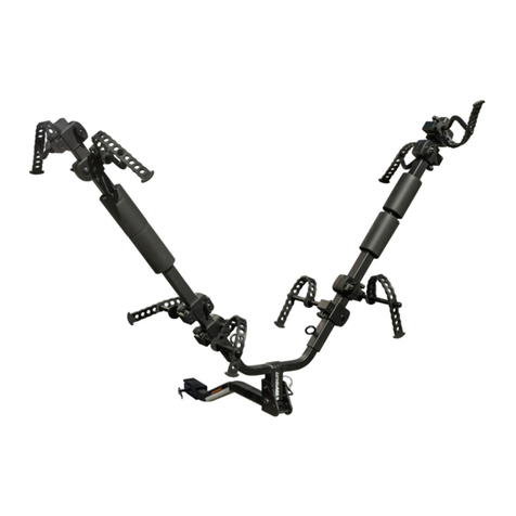
Let's Go Aero BikeWing-2 User manual

Let's Go Aero
Let's Go Aero GearDeck H00604 User manual
Let's Go Aero
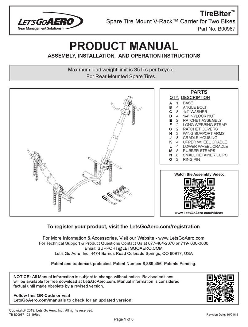
Let's Go Aero TireBiter V-Rack User manual
Let's Go Aero
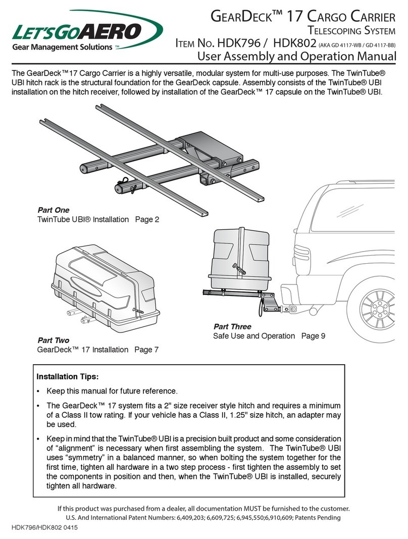
Let's Go Aero GearDeck 17 Installation instructions
Let's Go Aero
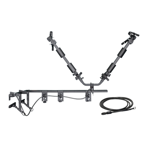
Let's Go Aero B01809 User manual

Let's Go Aero
Let's Go Aero BLACK BOX User manual
Let's Go Aero
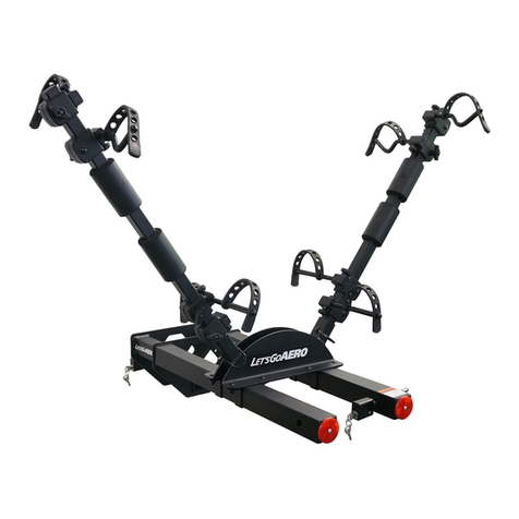
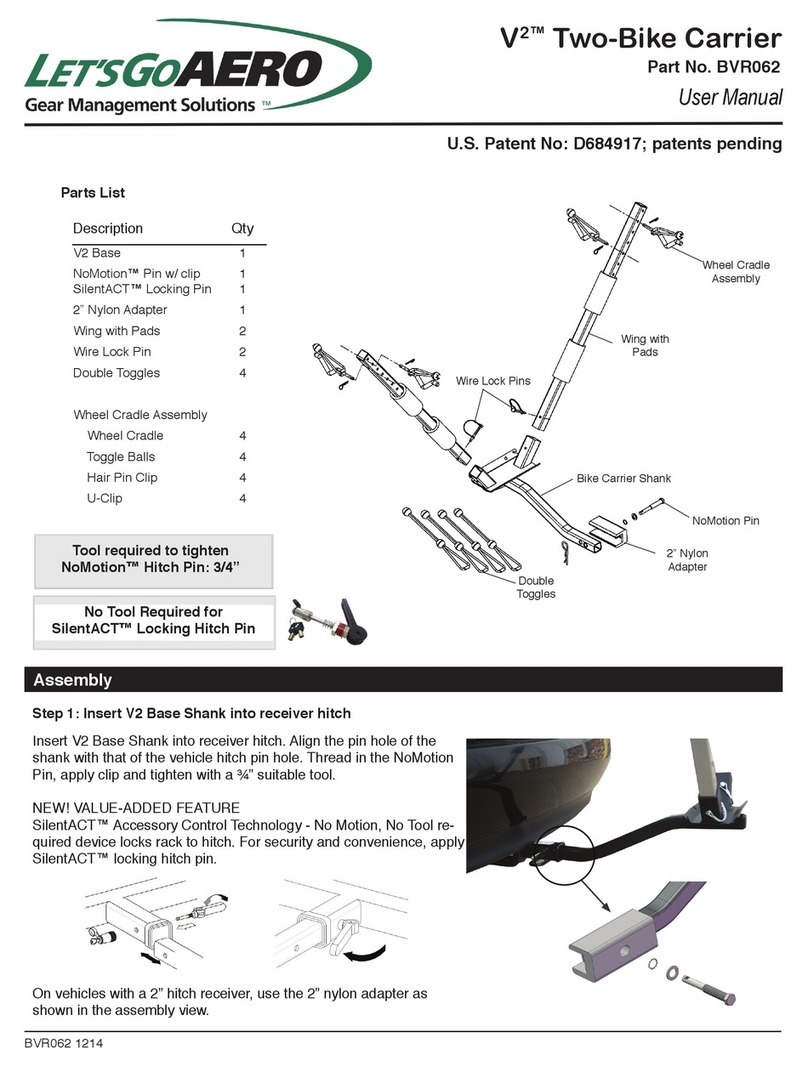
Let's Go Aero V2 Two-Bike Carrier User manual

Let's Go Aero
Let's Go Aero V-Lectric B01175 User manual
Let's Go Aero
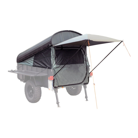
Let's Go Aero HexCap User manual
Let's Go Aero
Let's Go Aero T01991 User manual

Let's Go Aero
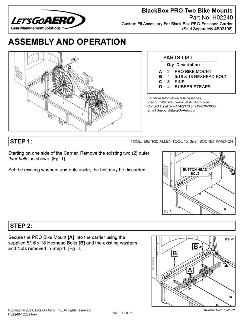
Let's Go Aero HideOut Package H01564 User manual
Let's Go Aero
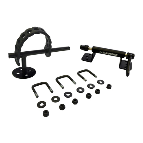
Let's Go Aero BlackBox PRO Installation instructions
Let's Go Aero
Let's Go Aero Fork-IT H01793 Installation instructions
Popular Automobile Accessories manuals by other brands

ULTIMATE SPEED
ULTIMATE SPEED 279746 Assembly and Safety Advice

SSV Works
SSV Works DF-F65 manual

ULTIMATE SPEED
ULTIMATE SPEED CARBON Assembly and Safety Advice

Witter
Witter F174 Fitting instructions

WeatherTech
WeatherTech No-Drill installation instructions

TAUBENREUTHER
TAUBENREUTHER 1-336050 Installation instruction
